H4JAMP-4-410UHF 30W POWER AMPLIFIER
Zetron
Click to zoom
Application Details
- Equipment Class
- AMP - Amplifier
- Date of Grant
- Dec 27, 2012
- Application Purpose
- Original Equipment
- Date of Application
- Dec 27, 2012
- Equipment Note
- UHF 30W POWER AMPLIFIER
- Frequency Range
- 406.10000000 - 430.00000000
- Company
- Zetron
- Country
- Canada
Documents & Files
Document Text
Text extracted from the exhibit documents filed with the FCC. Open a document above to read the original.
Users Manual
RF Exposure Warning Exposure to radio frequency (RF) energy has been identified as a potential environmental factor that must be considered before a radio transmitter can be authorized or licensed. The FCC and IC have therefore developed maximum permissible exposure (MPE) limits for field strength and power density, listed in FCC 47 CFR § 1.1310 and IC RSS.102 Issue 2 Sect 4. The FCC has furthermore determined that determination of compliance with these exposure limits, and preparation of an Environmental Assessment (EA) if the limits are exceeded, is necessary only for facilities, operations and transmitters that fall into certain risk categories, listed in FCC 47 CFR § 1.1307 (b), Table 1. All other facilities, operations and transmitters are categorically excluded from making such studies or preparing an EA, except as indicated in FCC 47 CFR §§ 1.1307 (c) and (d). Revised FCC OET Bulletin 65 (Edition 97.01) and IC RSS.102 Issue 2 provide assistance in determining whether a proposed or existing transmitting facility, operation or device complies with RF exposure limits. In accordance with OET Bulletin 65, FCC 47 CFR § 1.1307 (b) and RSS.102 Issue Sect 2.5, the Codan Radio Communications transmitter manufactured in Canada is categorically excluded from routine evaluation or preparing an EA for RF emissions and this exclusion is sufficient basis for assuming compliance with FCC/IC MPE limits. This exclusion is subject to the limits specified in FCC 47 CFR §§ 1.1307 (b), 1.1310 and IC RSS.102 Issue 2 Sect 4. Codan Radio Communications has no reason to believe that the excluded transmitter encompasses exceptional characteristics that could cause non.compliance. Notes: • The FCC and IC’s exposure guidelines constitute exposure limits, not emission limits. They are relevant to locations that • are accessible to workers or members of the public. Such access can be restricted or controlled by appropriate means (i.e., fences, warning signs and others). • The FCC and IC’s limits apply cumulatively to all sources of RF emissions affecting a given site. Sites exceeding these • limits are subject to an EA and must provide test reports indicating compliance. RF Safety Guidelines and Information Base and Repeater radio transmitters are designed to generate and radiate RF energy by means of an external antenna, typically mounted at a significant height above ground to provide adequate signal coverage. To reduce potential radio interference to other users, the antenna type and its gain should be so chosen that the equivalent isotropically radiated power (EIRP) is not more than that permitted for successful communication. The following antenna installation guidelines are extracted from Appendix A from OET Bulletin 65 and must be adhered to in order to ensure RF exposure compliance: Non.building.mounted Antennas: • Height above ground level to lowest point of antenna ≥ 10 m • Power ≤ 1000 W ERP (1640 W EIRP) Building.mounted Antennas: Power ≤ 1000 W ERP (1640 W EIRP) The following RF Safety Guidelines should be observed when working in or around transmitter sites: • The minimum safe distance the user should be from the transmitter antenna while transmitting is 142 cm for transmitters 8W or less and 300 cm for amplifiers 30W or less. This assumes a maximum antenna EIRP of 15 dBi. • Do not work on or around any transmitting antenna while RF power is applied. • Before working on an antenna, disable the appropriate transmitter and ensure a “DO NOT USE” or similar sign is placed on or near the PTT or key.up control. • Assume all antennas are active unless specifically indicated otherwise. • Never operate a transmitter with the cover removed. • Ensure all personnel entering a transmitter site have electromagnetic energy awareness training. For more information on RF energy exposure and compliance, please refer to the following: • FCC Code of Regulations; 47 CFR §§ 1.1307 and 1.1310 • FCC OET Bulletin 65, Edition 97.01, “Evaluating Compliance with FCC Guidelines for Human Exposure to Radiofrequency Electromagnetic Fields” • http://www.fcc.gov/oet/rfsafety/ • IC RSS.102 Issue 2, “Radio Frequency Exposure Compliance of Radio Communication Apparatus” 2 Power Amplifier AMP-4-410-30-00 User Manual 1. General Description The power amplifier (PA) is a one stage unit, working in AB-class operation mode. In addition to the power amplifier section, the PA contains the power control, status monitoring and protecting circuitry, as well as voltage regulation for supplying the RF and main control circuits. The output power may be controlled either by the external analog signal (remote control), or by potentiometer, accessible from the front panel (local control). The voltage regulator turns on, when all four of the following conditions are present: - remote control voltage (in the case of remote control) is greater than 1 V; - input power is not less than 0.5 W; - the case temperature does not exceed + 85°C; - power supply voltage does not exceed 17 V. If any of three first mentioned conditions is not met, unit remains in stand-by mode. The PA is provided with a forced air cooling system and is protected against load mismatch, overheating and overvoltage. The load mismatch protection smoothly reduces output power as the load VSWR increases above 2:1. Three LED on the front panel indicate the unit status. The green LED “TX” shows that the output power is between the nominal (>30 W) and minimum set power ( ~20 W). The red LED “G/F” (general fault) turns on during overheating or overvoltage. The red LED “VSWR” is active when the load VSWR is above 2:1. The PA has three outputs (open collector) for remote status monitoring. In an alarm state, the level is pulled low. 2. General parameters. - Frequency range, MHz . . . . . . . . . . . . . . . . . . . . . . . . . . . . . . . . . . . . . . . . . . . . . . . . . 380 - 430; - Output power, W; o nominal . . . . . . . . . . . . . . . . . . . . . . . . . . . . . . . . . . . . . . . . . …
Text truncated - open the document above for the full version.
Cover Letter(s)
December 6, 2012 Federal Communications Commission, Equipment Approval Services, P.O. Box 358315 Pittsburgh, PA 15251-5315 FCC ID: H4JAMP-4-410 Model #: AMP-4-410-30-00 Product Name: MT-4E UHF 30 W Power Amplifier Request for Confidentiality Pursuant to Sections 0.457(d)(1)(ii) and 0.459 of the commission’s rules, we hereby request that the following documents be held confidential: Operational Description All Schematics Parts Listings Block Diagram Tune Up Procedure These materials contain trade secrets and proprietary information and are not customarily released to the public. The public disclosure of this information might be harmful to the company and provide unjustified benefits to our competitors. Dated this 6 Day of December 20 12 By: MICHAEL J CYR Signature Printed Title: COMMUNICATION SYSTEMS ENGINEER On behalf of : CODAN RADIO COMMUNICATIONS Telephone: (250)382-8268 MC/vs
External Photos
AMP-4-410-30-00 – External Photos 1 – PA Front AMP-4-410-30-00 – External Photos 2 – PA Back AMP-4-410-30-00 – External Photos 3 – PA Top AMP-4-410-30-00 – External Photos 4 – PA Bottom AMP-4-410-30-00 – External Photos 5 – PA Side (Left) AMP-4-410-30-00 – External Photos 6 – PA Side (Right) AMP-4-410-30-00 – External Photos 7 –RF Section Side / Front
ID Label/Location Info
FRONT PANEL BOTTOM TOP LEFT SIDE COVER EQUIPMENT ID LABEL FORMAT & LOCATION AMP-4/410 30 Watt VHF Power Amplifier MODEL: IC: FCC ID: SERIAL #: DATE: TM DATE: 4 Dec 2012 TITLE: AMP-4-410-30-00 Label Format and Location DRAWN BY: REV DATE: 5 Dec 2012 DWG No: 1 11 21 2 12 22 3 13 23 4 14 24 5 15 25 6 16 26 7 17 27 8 18 28 9 19 29 10 20 30 A A. McLENNAN 2.25" 1.375"
Internal Photos
AMP-4-410-30-00 – Internal Photos 1 – Alarm Board Front 2 – Alarm Board Back 3 – AMP Board Front 4 – AMP Board Back 5 – PA Top 6 – PA Bottom 7 – Alarm Board + Front Panel Side
Test Report
FCC PT 90 AMPLIFIER AND IC RSS-131, RSS-GEN TEST REPORT APPLICANT CODAN RADIO COMMUNICATIONS ADDRESS 43 ERIE STREET VICTORIA BC V8V 1P8 CANADA FCC ID H4JAMP-4- 410 IC LABEL 142A-AMP4410 MODEL NUMBER AMP-4- 410-30 -00 PRODUCT DESCRIPTION UHF 30W POWER AMPLIFIER DATE SAMPLE RECEIVED 11/27/2012 DATE TESTED 11/28/2012 TESTED BY NAM NGUYEN APPROVED BY MARIO R. DE ARANZETA TIMCO REPORT NO. 3043AUT12TestReport.doc TEST RESULTS PASS FAIL THE ATTACHED REPORT SHALL NOT BE REPRODUCED EXCEPT IN FULL WITHOUT THE WRITTEN APPROVAL OF TIMCO ENGINEERING, INC. 849 NW STATE ROAD 45 NEWBERRY, FL 32669 USA PH: 888.472.2424 OR 352.472.5500 FAX: 352.472.2030 EMAIL: [email protected] HTTP://WWW.TIMCOENGR.COM Certificate # 0955-01 Applicant: CODAN RADIO COMMUNICATIONS FCC ID: H4JAMP-4- 410 IC: 142A -AMP4410 MODEL #: AMP-4- 410-30 -00 Report: D\Danelec\3043AUT12\3043AUT12TestReport.doc Page 2 of 24 TABLE OF CONTENTS ATTESTATION STATEMENT ............................................................................ 3 REPORT SUMMARY ........................................................................................ 4 TEST ENVIRONMENT AND TEST SETUP ......................................................... 4 DUT DESCRIPTION ......................................................................................... 5 TEST EQUIPMENT .......................................................................................... 6 TEST PROCEDURES ....................................................................................... 7 TEST RESULTS ............................................................................................... 9 RF POWER OUTPUT ........................................................................................................... 9 OCCUPIED BANDWIDTH .................................................................................................. 10 SPURIOUS EMISSIONS AT ANTENNA TERMINALS (CONDUCTED) .................................... 20 FIELD STRENGTH OF SPURIOUS EMISSIONS (RADIATED) ............................................... 21 POWER LINE CONDUCTED INTERFERENCE .................................................................... 22 PASSBAND GAIN AND 20 dB BANDWIDTH ....................................................................... 23 Applicant: CODAN RADIO COMMUNICATIONS FCC ID: H4JAMP-4- 410 IC: 142A -AMP4410 MODEL #: AMP-4- 410-30 -00 Report: D\Danelec\3043AUT12\3043AUT12TestReport.doc Page 3 of 24 ATTESTATION STATEMENT This equipment has been tested in accordance with the standards identified in the referenced test report. To the best of my knowledge and belief, these tests were performed using the measurement procedures described in this report. Test Certificate #0955-01 All instrumentation and accessories used to test products for compliance to the indicated standards are calibrated regularly in accordance with ISO 17025 requirements. I attest that the necessary measurements were made by me or under my supervision, at Timco Engineering, Inc. located at 849 N.W. State Road 45, Newberry, Florida 32669 USA. Authorized by: Mario R. de Aranzeta Signature: Function: Test Lab Supervisor / Engineer Date: 12/11/2012 Applicant: CODAN RADIO COMMUNICATIONS FCC ID: H4JAMP-4- 410 IC: 142A -AMP4410 MODEL #: AMP-4- 410-30 -00 Report: D\Danelec\3043AUT12\3043AUT12TestReport.doc Page 4 of 24 REPORT SUMMARY Disclaimer The test results relate only to the items tested. Purpose of Test To show the DUT in compliance with FCC CFR 47, Part 90 and IC RSS-131 requirements for amplifiers Test Procedures ANSI/TIA 603-C: 2004 FCC CFR 47 Part 90 IC RSS-131 ANSI C63.4: 2003 Related Approval N/A TEST ENVIRONMENT AND TEST SETUP Test Facility All tests were conducted by: Timco Engineering Inc. 849 NW State Road 45, Newberry, FL 32669 USA Laboratory Test Condition Temperature: 26ºC Relative humidity: 50%. Deviation from the standards No deviation Modification to the DUT No modification was made. Test Exercise (software etc.) The DUT was placed in continuous transmitting mode of operation. System Setup Stand alone device. Applicant: CODAN RADIO COMMUNICATIONS FCC ID: H4JAMP-4- 410 IC: 142A -AMP4410 MODEL #: AMP-4- 410-30 -00 Report: D\Danelec\3043AUT12\3043AUT12TestReport.doc Page 5 of 24 DUT DESCRIPTION Manufactured by CODAN RADIO COMMUNICATIONS Product Description UHF 30W POWER AMPLIFIER FCC ID H4JAMP-4-410 IC Label 142A-AMP4410 M/N AMP-4-410-30-00 Operating Freq (406.10 – 430.00) MHz Modulation N/A (Amplifier) Power Source 13.8 VDC Test Item Preproduction Type of DUT Fixed Amplifier Applicant: CODAN RADIO COMMUNICATIONS FCC ID: H4JAMP-4- 410 IC: 142A -AMP4410 MODEL #: AMP-4- 410-30 -00 Report: D\Danelec\3043AUT12\3043AUT12TestReport.doc Page 6 of 24 TEST EQUIPMENT Device Manufacturer Model Serial Number Cal/Char Date Due Date 3-Meter Semi- Anechoic Chamber Panashield N/A N/A Listed 12/31/11 12/31/13 AC Voltmeter HP 400FL 2213A14499 CAL 6/12/11 6/12/13 Antenna: Active Loop ETS-Lindgren 3117 00041534 CAL 10/5/12 10/5/14 Frequency Counter HP 5385A 2730A03025 CAL 8/17/11 8/17/13 Hygro- Thermometer Extech 445703 0602 CAL 6/15/11 6/15/13 Modulation Analyzer HP 8901A 3435A06868 CAL 7/18/11 7/18/13 Digital Multimeter Fluke FLUKE-77 35053830 CAL 9/9/11 9/9/13 Power Meter Boonton Electronics 4531 11793 CAL 11/12/2011 11/12/2013 EMI Receiver Rohde & Schwarz ESIB40 100274 CAL 3/16/2012 3/16/2014 Analyzer Tan Tower Preamplifier HP 8449B-H02 3008A00372 CAL 10/28/11 10/28/13 Analyzer Tan Tower Quasi- Peak Adapter HP 85650A 3303A01690 CAL 10/28/11 10/28/13 Analyzer Tan Tower RF Preselector HP 85685A 3221A01400 CAL 10/28/11 10/28/13 Analyzer Tan Tower Spectrum Analyzer HP 8566B Opt 462 3138A07786 3144A20661 CAL 10/28/11 10/28/13 Temperature Chamber Tenney Engineering TTRC 11717-7 CHAR 2/22/12 2/22/13 Antenna ETS 3117 35923 12/7/2011 12/7/2013 Antenna Electro metrics LPA-25 1122 5/04/2011 5/04/2013 Antenna Electro metrics BIA-25 1096 5/04/2011 5/04/2013 Applicant: CODAN RADIO COMMUNICATIONS FCC ID: H4JAMP-4- 410 IC: 1…
Text truncated - open the document above for the full version.
Contact Information
Applicant
Werner Hoepf(Senior Compliance Analyst)
Test Firm
Timco Engineering, Inc.Bruno Clavier
Technical Specifications
| # | Rule Parts | Frequency Range | Power Output | Emission | Tolerance |
|---|---|---|---|---|---|
| 8 | 22,9 | 406.1 MHz - 430 MHz | 30 W | G3E | Amp |
Other Applications from Zetron
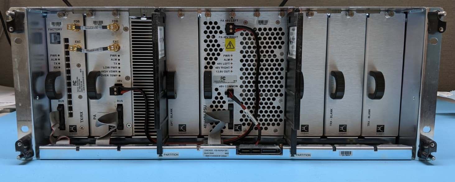
H4JCASC165B
Feb 18, 2020Cascade VHF Transceiver
Equipment Class
TNB - Licensed Non-Broadcast Station Transmitter
H4JAMP-4-800
Aug 17, 2014700/800 MHz 30W POWER AMPLIFIER
Equipment Class
AMP - Amplifier
H4JAMP-4-470
Dec 27, 2012UHF 30W POWER AMPLIFIER
Equipment Class
AMP - Amplifier
H4JAMP-4-150
Dec 14, 201130W VHF POWER AMPLIFIER
Equipment Class
AMP - Amplifier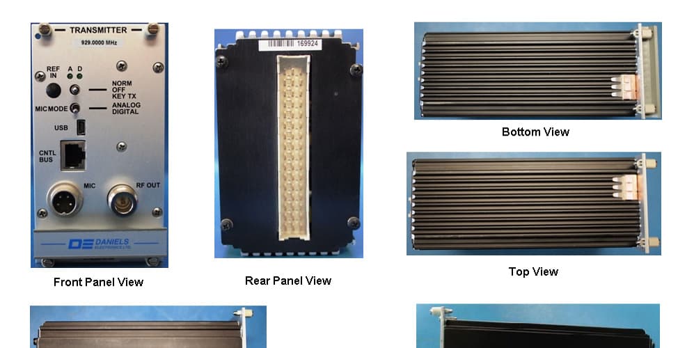
H4JUT-4E900
Jul 13, 2011AUDIO AND PAGING BASE STATION TRANSMITTER
Equipment Class
TNB - Licensed Non-Broadcast Station Transmitter