H4JAMP-4-800700/800 MHz 30W POWER AMPLIFIER
Zetron
Click to zoom
Application Details
- Equipment Class
- AMP - Amplifier
- Date of Grant
- Aug 17, 2014
- Application Purpose
- Original Equipment
- Date of Application
- Aug 14, 2014
- Equipment Note
- 700/800 MHz 30W POWER AMPLIFIER
- Frequency Range
- 854.00000000 - 869.00000000
- Company
- Zetron
- Country
- Canada
Documents & Files
Document Text
Text extracted from the exhibit documents filed with the FCC. Open a document above to read the original.
Users Manual
RF Exposure Warning Exposure to radio frequency (RF) energy has been identified as a potential environmental factor that must be considered before a radio transmitter can be authorized or licensed. The FCC and IC have therefore developed maximum permissible exposure (MPE) limits for field strength and power density, listed in FCC 47 CFR § 1.1310 and IC RSS-102 Issue 2 Sect 4. The FCC has furthermore determined that determination of compliance with these exposure limits, and preparation of an Environmental Assessment (EA) if the limits are exceeded, is necessary only for facilities, operations and transmitters that fall into certain risk categories, listed in FCC 47 CFR § 1.1307 (b), Table 1. All other facilities, operations and transmitters are categorically excluded from making such studies or preparing an EA, except as indicated in FCC 47 CFR §§ 1.1307 (c) and (d). Revised FCC OET Bulletin 65 (Edition 97-01) and IC RSS-102 Issue 2 provide assistance in determining whether a proposed or existing transmitting facility, operation or device complies with RF exposure limits. In accordance with OET Bulletin 65, FCC 47 CFR § 1.1307 (b) and RSS-102 Issue Sect 2.5, the Codan Radio Communications transmitter manufactured in Canada is categorically excluded from routine evaluation or preparing an EA for RF emissions and this exclusion is sufficient basis for assuming compliance with FCC/IC MPE limits. This exclusion is subject to the limits specified in FCC 47 CFR §§ 1.1307 (b), 1.1310 and IC RSS-102 Issue 2 Sect 4. Codan Radio Communications has no reason to believe that the excluded transmitter encompasses exceptional characteristics that could cause non- compliance. Notes: • The FCC and IC’s exposure guidelines constitute exposure limits, not emission limits. They are relevant to locations that • are accessible to workers or members of the public. Such access can be restricted or controlled by appropriate means (i.e., fences, warning signs and others). • The FCC and IC’s limits apply cumulatively to all sources of RF emissions affecting a given site. Sites exceeding these • limits are subject to an EA and must provide test reports indicating compliance. RF Safety Guidelines and Information Base and Repeater radio transmitters are designed to generate and radiate RF energy by means of an external antenna, typically mounted at a significant height above ground to provide adequate signal coverage. To reduce potential radio interference to other users, the antenna type and its gain should be so chosen that the equivalent isotropically radiated power (EIRP) is not more than that permitted for successful communication. The following antenna installation guidelines are extracted from Appendix A from OET Bulletin 65 and must be adhered to in order to ensure RF exposure compliance: Non-building-mounted Antennas: • Height above ground level to lowest point of antenna ≥ 10 m • Power ≤ 1000 W ERP (1640 W EIRP) Building-mounted Antennas: Power ≤ 1000 W ERP (1640 W EIRP) The following RF Safety Guidelines should be observed when working in or around transmitter sites: • The minimum safe distance the user should be from the transmitter antenna while transmitting is 57 cm amplifiers 30W or less. This assumes a maximum antenna EIRP of 15 dBi. • Do not work on or around any transmitting antenna while RF power is applied. • Before working on an antenna, disable the appropriate transmitter and ensure a “DO NOT USE” or similar sign is placed on or near the PTT or key-up control. • Assume all antennas are active unless specifically indicated otherwise. • Never operate a transmitter with the cover removed. • Ensure all personnel entering a transmitter site have electromagnetic energy awareness training. For more information on RF energy exposure and compliance, please refer to the following: • FCC Code of Regulations; 47 CFR §§ 1.1307 and 1.1310 • FCC OET Bulletin 65, Edition 97-01, “Evaluating Compliance with FCC Guidelines for Human Exposure to Radiofrequency Electromagnetic Fields” • http://www.fcc.gov/oet/rfsafety/ • IC RSS-102 Issue 2, “Radio Frequency Exposure Compliance of Radio Communication Apparatus” 2 FCC Part 90.203(e) Compliance This radio complies with 47 CFR Part 90.203(e) in that the operator cannot program and transmit on frequencies, other than those stated by the manufacturer, service or maintenance personnel, using the equipment's external operation controls. It is noted that the FCC rules would be violated if this radio is used to operate on frequencies outside of FCC (Part 90 and Part 22) Frequency Bands for users other than the (Federal Government). FCC RF Exposure Requirements CAUTION: This transmitter must be restricted to work related operations in a Controlled RF exposure environment. All qualified end-users of this device must have the knowledge to control their exposure conditions and/or duration, and the exposure conditions and/or duration of their passengers and bystanders, to comply with the General Population / Uncontrolled MPE limit and requirements. IC RSS-GEN, Sec 7.1.2 Warning Statement- (Required for Transmitters) ENGLISH: Under Industry Canada regulations, this radio transmitter may only operate using an antenna of a type and maximum (or lesser) gain approved for the transmitter by Industry Canada. To reduce potential radio interference to other users, the antenna type and its gain should be so chosen that the equivalent isotropically radiated power (e.i.r.p.) is not more than that necessary for successful communication. FRENCH: Conformément à la réglementation d'Industrie Canada, le présent émetteur radio peut fonctionner avec une antenne d'un type et d'un gain maximal (ou inférieur) approuvé pour l'émetteur par Industrie Canada. Dans le but de réduire les risques de brouillage radioélectrique à l'intention des autres utilisateurs, il faut choisir le type d'antenne et son gain de sorte que la puissance isotrope rayonnée quivalente (p.i.r.e.) ne dépassepas l'intensité nécessair…
Text truncated - open the document above for the full version.
Cover Letter(s)
June 4, 2014 Federal Communications Commission, Equipment Approval Services, P.O. Box 358315 Pittsburgh, PA 15251-5315 FCC ID: H4JAMP-4 -800 Model #: AMP-4 -800-30-00 Product Name: MT-4E 700/800 MHz 30 W Power Amplifier Request for Confidentiality Pursuant to Sections 0.457(d)(1)(ii) and 0.459 of the commission’s rules, we hereby request that the following documents be held confidential: • Operational Description • All Schematics • Block Diagram • Tuning Procedure These materials contain trade secrets and proprietary information and are not customarily released to the public. The public disclosure of this information might be harmful to the company and provide unjustified benefits to our competitors. Dated this 4 Day of June 20 14 By: MICHAEL J CYR Signature Printed Title: PRODUCT MANAGER On behalf of : CODAN RADIO COMMUNICATIONS Telephone: (250)382-8268 MC
Cover Letter(s)
June 4, 2014 Federal Communications Commission Authorization and Evaluation Division 7435 Oakland Mills Road Columbia, MD 21046 Subject: Extended Frequencies Justification Gentlemen: We, Codan Radio Communications, would like to submit the following justification to show the frequency range (768-869 MHz) on the Grant of Equipment Authorization under Part 90 for our FCC ID: H4JAMP-4-800 Per the FCC’S KDB 634817 guidance, as an alternative to listing the exact frequencies, we acknowledge that it’s a violation of the FCC Rules if this device operates on unauthorized frequencies. This amplifier is i ntended for use by federal agencies, public agencies, emergency services, as well as commercial, business, and industrial services. Additionally, it will be used in other countries that accept the FCC Grant of Equipment Authorization. These services account for a majority of users as described in the below table. Frequencies MHz Non-Fed FCC Rule Part Federal ITU Region 768-775 90R 2 789- 793 X 793-805 90R 2 806-809 90S 2 809-823 90 2 851-854 90S 2 854-894 X 2 This amplifier c o mplies with 47 CFR Part 90.203(e) in that the operator cannot program and transmit on frequencies, other than those programmed by the manufacturer, service or maintenance personnel, using the equipment’s external operation controls. T sj Sincerely, By: MICHAEL J CYR Signature Printed Title: PRODUCT MANAGER On behalf of : CODAN RADIO COMMUNICATIONS Telephone: (250)382-8268 MC
External Photos
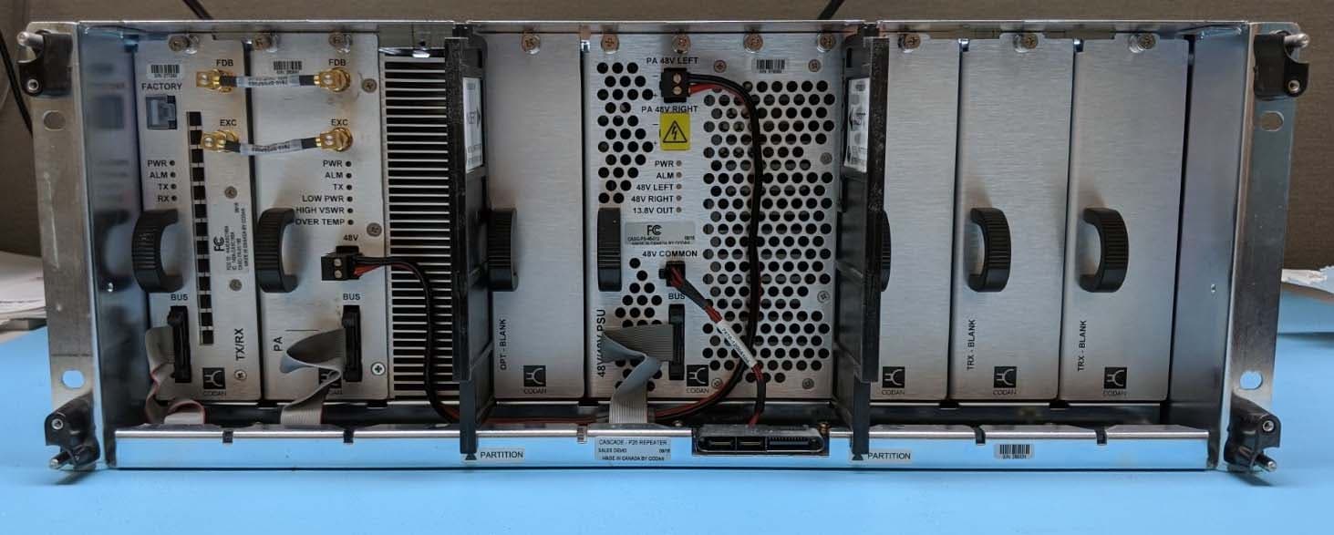
AMP-4 -800-30-00 – External Photos AMP-4 -800-30-00 – External Photos AMP-4 -800-30-00 – External Photos AMP-4 -800-30-00 – External Photos
ID Label/Location Info
EQUIPMENT ID LABLE FORMAT & LOCATION AMP-4/800 700/800 30 Watt Power Amplif ier
Internal Photos
AMP-4 -800-30-00 – Internal Photos
RF Exposure Info
RF Exposure Evaluation Report APPLICANT CODAN RADIO COMMUNICATIONS 43 ERIE STREET VICTORIA, BC V8V 1P8 CANADA FCC ID H4JAMP-4-800 MODEL NUMBER AMP-4-800-30 PRODUCT DESCRIPTION 30W AMPLIFIER STANDARD APPLIED CFR 47 Part 2.1091 PREPARED BY Cory Leverett We, TIMCO ENGINEERING, INC. would like to declare that the device has been evaluated in accordance with 47 CFR Part 2.1091 and meets the requirements. The attached report shall not be reproduced except in full without the written approval of TIMCO ENGINEERING, INC. 849 NW STATE ROAD 45 NEWBERRY, FL 32669 USA PH: 888.472.2424 OR 352.472.5500 FAX: 352.472.2030 EMAIL: [email protected] HTTP://WWW.TIMCOENGR.COM Applicant: CODAN RADIO COMMUNICATIONS FCC ID: H4JAMP-4-800 Report: C\CODAN_H4J\RF Exposure Rpt Page 2 of 5 GENERAL REMARKS Attestations This equipment has been evaluated in accordance with the standards identified in this report. To the best of my knowledge and belief, these evaluations were performed using the procedures described in this report. I attest that the necessary evaluations were made, under my supervision, at: Timco Engineering Inc. 849 NW State Road 45 Newberry, Fl 32669 Authorized Signatory Name: Cory Leverett Engineering Project Manager Date: 6/17/14 Applicant: CODAN RADIO COMMUNICATIONS FCC ID: H4JAMP-4-800 Report: C\CODAN_H4J\RF Exposure Rpt Page 3 of 5 GENERAL INFORMATION EUT Description 30W 800 MHz AMPLIFIER FCC ID H4JAMP-4-800 Model Number AMP-4-800-30 Frequency Range 768-869MHz Type of Emission F3E, F1E Modulation FM EUT Power Source 110–120Vac/50– 60Hz DC Power 12V Battery Operated Exclusively Test Item Prototype Pre-Production Production Type of Equipment Fixed Mobile Portable Test Conditions The temperature was 26ºC with a relative humidity of 64%. Revision History to the EUT None Test Facility Timco Engineering Inc. at 849 NW State Road 45 Newberry, FL 32669 USA. Applicant: CODAN RADIO COMMUNICATIONS FCC ID: H4JAMP-4-800 Report: C\CODAN_H4J\RF Exposure Rpt Page 4 of 5 RF Exposure Requirements General information Device type: Part 90 RF amplifier designed to increase the RF output power of a push to talk type of radio. Devices that operate under Part 90 of this chapter are subject to RF exposure evaluation prior to equipment authorization or use. Antenna The manufacturer does not specify an antenna, but a typical antenna has a gain of 0 dBi. Configuration Antenna p/n Type Max. Gain (dBi) Fixed mounted Any omni 0 Operating configuration and exposure conditions: The conducted output power is shown in the table below. Typical use qualifies for a maximum duty cycle factor of 100%. Operation: A typical installation consists of an antenna system with a 10 meter coaxial cable of the type RG 213/ U type which has a loss as follows; Nom. Attenuation for RG 213/U: Frequency MHz Attenuation per 100ft. dB 1 .27 10 .55 50 1.3 100 1.9 200 2.7 400 4.1 700 6.5 900 7.6 1000 8.0 4000 21.5 MPE Calculation: Applicant: CODAN RADIO COMMUNICATIONS FCC ID: H4JAMP-4-800 Report: C\CODAN_H4J\RF Exposure Rpt The minimum separation distance is calculated as follows: The limit for general uncontrolled exposure environment is shown in FCC rule Part 1.11310, Table 1. Max P ow e r 42W equalsMax P ow e r 42000mW Duty Cycle 100%equals Duty Factor 1 numeric Antenna Gain0 dBiequals Gain numeric 1 numeric Coax Loss2.6dBGain - Coax Los0.549541numeric Power Density0.6 mW/cm 2 Frequency869 MHz Frequency ranPower denEnter this value MHz mW/cm 2 mW/cm 2 0.3-1.34100100 1.34-30 180/f 2 0.0 30-3000.20.2 300-1,500f /15000.6 1,500-100,00011 f = frequency in MHz Minimum Separation Distance55cm0.55m Minimum Seperation in Inches21.76599Inches Minimum Separation Distance for Mobile or Fixed Devices General Population/Uncontrolled Exposure Insert values in yellow highlighted boxes to determine Minimum Separation Distance Enter power Density from the chart to the rightRule Part 1.1310, Table 1
Test Report
AMPLIFIER FCC PT 90 TEST REPORT Applicant CODAN RADIO COMMUNICATIONS Address 43 ERIE STREET VICTORIA, BC V8V 1P8 CANADA FCC ID H4JAMP-4-800 Model Number AMP-4-800-30 Product Description 30 W AMPLIFIER Standards Applied CFR 47 Part 90 IC Standard RSS-131, Issue 2, July 2003 IC Standard RSS-GEN, Issue 3, December 2010 Date Sample Received 6/5/2014 Date Report Issued 6/11/2014 Date Tested 6/5-6/9/2014 Revised 8/12/14 Tested By CORY LEVERETT Approved By Sid Sanders Timco Report No. 945AUT14TestReport Rev1.docx Test Results PASS FAIL THE ATTACHED REPORT SHALL NOT BE REPRODUCED EXCEPT IN FULL WITHOUT THE WRITTEN APPROVAL OF TIMCO ENGINEERING, INC. 849 NW STATE ROAD 45 NEWBERRY, FL 32669 USA PH: 888.472.2424 OR 352.472.5500 FAX: 352.472.2030 Applicant: CODAN RADIO COMMUNICATIONS FCC ID: H4JAMP-4-800 Report: C\CODAN\945AUT14\945AUT14TestReport Rev1.docx Page 2 of 31 Table of Contents GENERAL REMARKS .................................................................................................... 3 EUT DESCRIPTION ..................................................................................................... 4 RF EXPOSURE INFORMATION: 47CFR 2.1093................................................................ 5 SUPPORTING EQUIPMENT ........................................................................................... 5 TEST PROCEDURES .................................................................................................... 6 TEST RESULTS ........................................................................................................... 7 RF POWER OUTPUT .................................................................................................. 7 SPURIOUS EMISSIONS AT ANTENNA TERMINALS (CONDUCTED) LOW END OF BAND ......... 8 SPURIOUS EMISSIONS AT ANTENNA TERMINALS (CONDUCTED)MIDDLE OF BAND ............. 9 SPURIOUS EMISSIONS AT ANTENNA TERMINALS (CONDUCTED)HIGH END OF BAND ....... 10 OCCUPIED BANDWIDTH ......................................................................................... 11 OCCUPIED BANDWIDTH LOW END OF THE BAND 25KHZ ANALOG ............................ 13 OCCUPIED BANDWIDTH LOW END OF THE BAND 12.5KHZ ANALOG .......................... 14 OCCUPIED BANDWIDTH LOW END OF THE BAND 12.5KHZ DIGITAL .......................... 15 OCCUPIED BANDWIDTH LOW END OF THE BAND 25KHZ ANALOG ............................ 16 OCCUPIED BANDWIDTH MIDDLE OF THE BAND 12.5KHZ ANALOG ............................ 17 OCCUPIED BANDWIDTH MIDDLE OF THE BAND 12.5KHZ DIGITAL ............................ 18 OCCUPIED BANDWIDTH HIGH END OF THE BAND 25KHZ ANALOG ........................... 19 OCCUPIED BANDWIDTH HIGH END OF THE BAND 12.5KHZ ANALOG ......................... 20 OCCUPIED BANDWIDTH HIGH END OF THE BAND 12.5KHZ DIGITAL ......................... 21 OCCUPIED BANDWIDTH 852.0125 MHZ 12.5 KHZ ANALOG NPSPAC.......................... 22 OCCUPIED BANDWIDTH 852.0125MHz 12.5 KHZ ANALOG NPSPAC ........................... 23 OCCUPIED BANDWIDTH 852.0125 MHz 12.5 kHz Digital NPSPAC .............................. 24 OCCUPIED BANDWIDTH 860.950 MHz EA Mask ..................................................... 25 OCCUPIED BANDWIDTH 816.0750 MHZ EA MASK ................................................... 26 EA EMISSION MASK ................................................................................................. 26 FIELD STRENGTH OF SPURIOUS EMISSIONS - RADIATED .......................................... 27 FIELD STRENGTH OF SPURIOUS EMISSIONS - RADIATED .......................................... 28 FIELD STRENGTH OF SPURIOUS EMISSIONS - RADIATED .......................................... 29 FIELD STRENGTH OF SPURIOUS EMISSIONS - RADIATED .......................................... 30 TEST EQUIPMENT ..................................................................................................... 31 Applicant: CODAN RADIO COMMUNICATIONS FCC ID: H4JAMP-4-800 Report: C\CODAN\945AUT14\945AUT14TestReport Rev1.docx Page 3 of 31 GENERAL REMARKS The attached report shall not be reproduced except in full without the written permission of Timco Engineering Inc. Summary The device under test does: fulfill the general approval requirements as identified in this test report not fulfill the general approval requirements as identified in this test report Attestations This equipment has been tested in accordance with the standards identified in this test report. To the best of my knowledge and belief, these tests were performed using the measurement procedures described in this report. All instrumentation and accessories used to test products for compliance to the indicated standards are calibrated regularly in accordance with ISO 17025 requirements. I attest that the necessary measurements were made, under my supervision, at: Timco Engineering Inc. 849 NW State Road 45 Newberry, Fl 32669 Authorized Signatory Name: Cory Leverett Engineering Project Manager Date: 6/11/2014 Table of contents Applicant: CODAN RADIO COMMUNICATIONS FCC ID: H4JAMP-4-800 Report: C\CODAN\945AUT14\945AUT14TestReport Rev1.docx Page 4 of 31 EUT DESCRIPTION EUT Description 800 MHz 30W AMPLIFIER FCC ID H4JAMP-4-800 Model Number AMP-4-800-30 Operating Frequency 768-869MHz No. of Channels NA Type of Emission F1D, F1E, F1W, F2D, F3D, F3E, G2B, G3E Modulation N/A Amplifier EUT Power Source 110–120Vac/50– 60Hz DC Power 13.8V Battery Operated Exclusively Test Item Prototype Pre-Production Production Type of Equipment Fixed Mobile Portable Test Conditions The temperature was 26ºC with a relative humidity of 50%. Revision History to the EUT None Test Exercise The EUT was operated in a normal mode.Using a Codan 800 MHz Transmitter and Amplifier Subrack Applicable Standards ANSI/TIA 603-D:2010, ANSI C63.4: 2009 FCC CFR 47 Part 90, IC Standard RSS-131 Test Facility Timco Engineering Inc. at 849 NW State Road 45 Newberry, FL 32669 USA. Manufactured by CODAN RADIO COMMUNICATIONS Table of contents Applicant: CODAN RADIO COMMUNICATIO…
Text truncated - open the document above for the full version.
Test Setup Photos
Test Setup Photo Applicant: CODAN RADIO COMMUNICATIONS FCC ID: H4JAMP-4-800 IC: 142A-AMP4800 MODEL #: AMP-4-800-30
Contact Information
Applicant
Werner Hoepf(Senior Compliance Analyst)
Technical Contact
Timco Engineering, Inc.Cory Leverett
[email protected]888-472-2424
849 NW State Road 45 · Newberry, Florida · United States
Non-Technical Contact
Timco Engineering, Inc.Sharon Hoffman
[email protected]888-472-2424
Test Firm
Timco Engineering, Inc.Bruno Clavier
Technical Specifications
| # | Rule Parts | Frequency Range | Power Output | Emission | Tolerance |
|---|---|---|---|---|---|
| 42 | 9 | 854 MHz - 869 MHz | 35 W | F3E | Amp |
Other Applications from Zetron
H4JCASC165B
Feb 18, 2020Cascade VHF Transceiver
Equipment Class
TNB - Licensed Non-Broadcast Station Transmitter
H4JAMP-4-410
Dec 27, 2012UHF 30W POWER AMPLIFIER
Equipment Class
AMP - Amplifier
H4JAMP-4-470
Dec 27, 2012UHF 30W POWER AMPLIFIER
Equipment Class
AMP - Amplifier
H4JAMP-4-150
Dec 14, 201130W VHF POWER AMPLIFIER
Equipment Class
AMP - Amplifier
H4JUT-4E900
Jul 13, 2011AUDIO AND PAGING BASE STATION TRANSMITTER
Equipment Class
TNB - Licensed Non-Broadcast Station Transmitter