H52PT-3519Modem Card
Puretek Industrial Co Ltd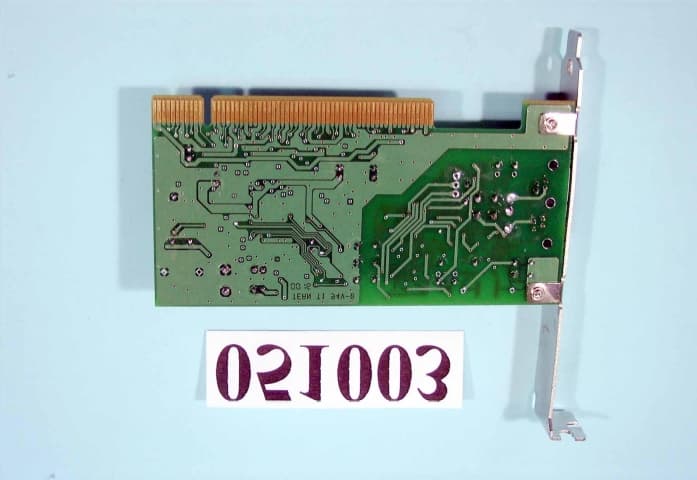
Click to zoom
Application Details
- Equipment Class
- JBP - Part 15 Class B Computing Device Peripheral
- Date of Grant
- Jul 30, 2000
- Application Purpose
- Original Equipment
- Date of Application
- May 24, 2000
- Equipment Note
- Modem Card
- Company
- Puretek Industrial Co Ltd
- Country
- Taiwan
Documents & Files
Document Text
Text extracted from the exhibit documents filed with the FCC. Open a document above to read the original.
Users Manual
Fax Modem Quick Installation Guide Ver. A 3519-0005 FCC Compliance To comply with the applicable sections of FCC Rules and Regulations, Parts 68 and 15, please follow these instructions: Do not connect your modem to a party line or to a coin-operated telephone. If your modem should cause a problem on the telephone line, it should be disconnected from the line until it can be determined whether the modem or another device on the phone line caused the problem. Only the manufacturer can make repairs to the modem. Other repair methods will void your warranty. If you have an external modem, use a properly constructed shielded cable to connect it to your computer. If your telephone company asks for the following information, please make it available: -Modem manufacturer -Model of modem i FCC Part 15 Operation is subject to the following two conditions: 1. This device may not cause harmful interference. 2. This device must accept any interference received including interference that may cause undesired operation. This equipment has been tested and found to comply with the limits for a Class B digital device, pursuant to Part 15 of the FCC Rules. These limits are designed to provide reasonable protection against harmful interference when the equipment is operated in a residential installation. This equipment generates, uses, and can radiate frequency energy and if not installed and used in accordance with the instructions, may cause harmful interference to radio communications. However, there is no guarantee that the interfer- ence to radio or television reception, which can be determined by turning the equipment off and on, the user is encouraged to try to correct the interference by one or more of the following measures: Reorient or relocate the receiving antenna. Increase the separation between the equipment and receiver. ii Connect the equipment into an outlet on a circuit different from that to which the receiver is connected. Consult the dealer or an experienced radio/ TV technician for help. Any changes or modifications not expressly approved by the grantee of this device could void the user authority to operate the equipment. FCC Part 68 Notice This equipment complies with Part 68 of the FCC rules. On the base of this unit is a label that contains, among other information, the FCC registration number and Ringer Equivalence Number (REN) for this equipment. If requested, this information must be given to your telephone company. The REN is used to determine the quantity of devices you may connect to your telephone line and still have all of those devices ring when your number is called. In most, but not all areas, the sum of the RENs of all devices should not exceed five (5.0). To be certain of the number of devices you may connect to your line, as determined by the total RENs, you should call your local tel- ephone company to determine the maximum RENs for your calling area. iii If the telephone company suspects a problem with your telephone line is related to an add-on electronic device, such as your modem, they have the right to temporarily suspend your service. It is your responsibility to remove from the telephone line any malfunctioning electronic communications equipment to avoid damage to the telephone system. If your equipment causes harm to the telephone network, the telephone company may discontinue your service temporarily. If possible, they will notify you in advance. But if advance notice is not practical, you will be notified as soon as possible. You will be informed of your right to file a com- plaint with the FCC. Your telephone company may make changes to its facilities, equipment, oper- ations, or procedures that could affect the proper functioning of your equipment. If they do, you will be notified in advance to give you an opportunity to maintain uninterrupted telephone service. The telephone company may ask that you discon- nect this equipment from the network until the problem has been corrected or until you are sure that the equipment is not malfunctioning. This equipment may not be used on coin service provided by the telephone company. Connection to party lines is subjected to state tariffs. If you experience trouble with this telephone equipment, please contact your place of purchase for information on obtaining service or repairs. iv Chapter 1 Introduction Features System Requirements Package Checklist Chapter 2 Installation Hardware Installation Installation Procedures for Windows NT 4.0 Installation Procedures for Windows 98 Installation Procedures for Windows 2000 Chapter 3 Commands Typing Commands AT Commands S-Register Definitions Table of Contents 11 12 1 13 14 14 17 18 19 112 12 Introduction The Voice/Fax/Data PCI Modem connects your computer to Internet, all kinds of BBS, and other fax modems. This manual describes the features, installation procedures and AT commands. Phone :Phone jack Line:Telephone line jack Features This modem supports the following communica- tion standards. ITU-T is known as CCITT. Data ITU-T V.90. Bell 103 & 212A. V.42bis & MNP 5 (Data compression). V.42 & MNP2-4 (Error correction). Fax V.17 (14400bps FAX). V.29 (9600bps FAX). Chapter 1 1 V.27ter (4800bps FAX). ITU-T V.34, V.32bis, V.32, V.22bis, V.21, V.22. To Phone To Line Voice Voice/Audio mode. System Requirements Windows NT 4.0, Windows 95, Windows 98, Windows 2000. Package Checklist The package contains the following items: One fax modem. One piece of phone cable. One CD. The fax modem Quick Installation Guide. If any of these items is missing or damaged, please contact your dealer or sales representative for assistance. Chapter 1 2 1.Make sure that your computer is switched off. Unplug the power cord from the wall socket. Also turn off all other peripherals you may have attached to your computer. 2.Select a free PCI slot. Remove the cover from the slot. Keep the screw. You will be using it in the next step. Hardware Installation Chapter 2 3 Installati…
Text truncated - open the document above for the full version.
External Photos
FCC ID : H52PT-3519Front side of EUT Number 1 051003-01.jpg FCC ID : H52PT-3519Rear side of EUT Number 2 051003-03.jpg
ID Label/Location Info
EXHIBIT A. FCC ID LABEL FCC ID:H52PT-3519 The next page shows the location of FCC ID on EUT. The following statement will be placed in the User’s Manual. FCC ID: H52PT-3519 0.5CM 4CM This device complies with Part 15 of the FCC Rules. Operation is subject to the following two conditions :(1) this device may not cause harmful interference, and (2) this device must accept any interference received, including interference that may cause undesired operation. Note: 1. Material and thickness:2 mi 1, white 2. Glue information : Permanent adhesive 3. Text color is black 4. Scale: 1:1
ID Label/Location Info
FCC ID LABEL LOCATION
Test Report
FCC TEST REPORT Report No. : F051003 SPORTON International Inc. FCC ID: H52PT-3519 TEL : 886-2-2696-2468Page No.: 1 of 23 FAX : 886-2-2696-2255Issued Date : May. 18, 2000 FCC TEST REPORT for CISPR PUB. 22 Class B Equipment: MODEM CARD Model No.: PT-3519 FCC ID: H52PT-3519 Filing Type: Original Grant Applicant: PURETEK INDUSTRIAL CO., LTD. 4F, NO. 12, LANE 235, PAO-CHIAO RD., HSINTIEN CITY, TAIPEI, TAIWAN, R.O.C. ! The test result refers exclusively to the test presented test model / sample. ! Without the written authorization of the test lab., the Test Report may not be copied. ! Certificate or Test Report must not be used by the applicant to claim the product in this test report endorsement by NVLAP or any agency of U.S. government. SPORTON International Inc. 6F, No.106, Sec. 1, Hsin Tai Wu Rd., Hsi Chih, Taipei Hsien, Taiwan, R.O.C. FCC TEST REPORT Report No. : F051003 SPORTON International Inc. FCC ID: H52PT-3519 TEL : 886-2-2696-2468Page No.: 2 of 23 FAX : 886-2-2696-2255Issued Date : May. 18, 2000 Table of Contents CERTIFICATE OF COMPLIANCE .............................................................................................................. 3 1. General Description of Equipment under Test..................................................................................... 4 1.1. Applicant .............................................................................................................................................................................................................. 4 1.2. Manufac turer ....................................................................................................................................................................................................... 4 1.3. Basic Description of Equipme nt under Test................................................................................................................................................... 4 1.4. Feature of Eq uipment under Tes t.................................................................................................................................................................... 4 2. Test Configuration of Equipment under Test....................................................................................... 5 2.1. Test Ma nner ........................................................................................................................................................................................................ 5 2.2. Description of Test S ystem............................................................................................................................................................................... 5 2.3. Connec tion Diagram o f Test Sys tem .............................................................................................................................................................. 8 3. Test Software ....................................................................................................................................... 8 4. General Information of Test ............................................................................................................... 10 4.1. Test Facility .......................................................................................................................................................................................................10 4.2. Standard for Methods o f Meas ure ment ........................................................................................................................................................10 4.3. Test in Comp liance with ..................................................................................................................................................................................10 4.4. Freque nc y Range Investigated ......................................................................................................................................................................10 4.5. Test Distance ....................................................................................................................................................................................................10 5. Test of Conducted Powerline............................................................................................................. 11 5.1. Major Measuring Instrume nts .........................................................................................................................................................................11 5.2. Test Procedures ...............................................................................................................................................................................................12 5.3. Typical Test Setup La yo ut o f Co nduc ted Powerline ...................................................................................................................................13 5.4. Test Res ult o f AC Powerline Cond ucted Emission.....................................................................................................................................14 5.5. Photograp hs o f Cond uc ted Powerline Tes t Configuration.........................................................................................................................15 6. Test of Radiated Emission.................................................................................................................. 17 6.1. Major Measuring Instrume nts .........................................................................................................................................................................17 6.2. Test Procedures ...............................................................................................................................................................................................17 6.3. Typical Test S…
Text truncated - open the document above for the full version.
Contact Information
Applicant
Yu-Hong Lee(R & D Manager)
886 2 2910-1310Fax: 886 2 2916-1004
Technical Contact
SPORTON International Inc.Kathy Lin
[email protected]886-2-26962468
75-23 19St. Fresh Meadows · Taipei Hsien, New York · United States
Non-Technical Contact
SPORTON International Inc.Kathy Lin
[email protected]718-468-4260
Test Firm
Sporton International Inc.W. Huang
Technical Specifications
| # | Rule Parts | Frequency Range | Power Output |
|---|---|---|---|
| 1 | 15B | - | - |
Other Applications from Puretek Industrial Co Ltd
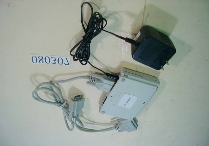
H52PT-3030
Oct 08, 2000Modem
Equipment Class
JBP - Part 15 Class B Computing Device Peripheral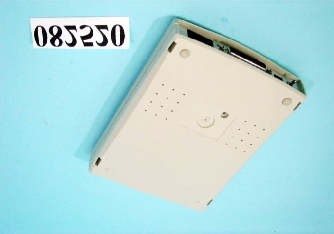
H52PT-3032
Oct 05, 2000Modem
Equipment Class
JBP - Part 15 Class B Computing Device Peripheral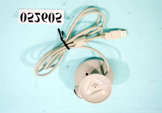
H52PT-6009
Oct 05, 2000CCD
Equipment Class
JBP - Part 15 Class B Computing Device Peripheral
H52PT-3036
Sep 27, 2000Modem
Equipment Class
JBP - Part 15 Class B Computing Device Peripheral
H52PT-3029
Sep 27, 2000Modem Card
Equipment Class
JBP - Part 15 Class B Computing Device Peripheral