H5P-WT11ECBluetooth Module
Topcon Corporation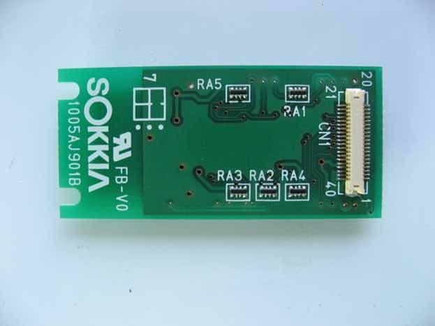
Click to zoom
Application Details
- Equipment Class
- DSS - Part 15 Spread Spectrum Transmitter
- Date of Grant
- Dec 21, 2009
- Application Purpose
- Original Equipment
- Date of Application
- Dec 21, 2009
- Equipment Note
- Bluetooth Module
- Frequency Range
- 2404.00000000 - 2478.00000000
- Company
- Topcon Corporation
- Country
- Japan
Documents & Files
Document Text
Text extracted from the exhibit documents filed with the FCC. Open a document above to read the original.
Users Manual
WT11ECUSER’S MANUAL Over View This device is a class 1,Bluetooth® 2.0+EDR (Enhanced Data Rates)module. Physical Specifications Table A-1 Physical Specification Dimensions W: 43mm D: 20mm H: 4.3mm Weight 4g Input / output UART interface/Power/antenna Input voltage 3.3V5% Operating temperature -40 to +85 Storage temperature -40 to +85 Wireless specifications Table A-2 Wireless Specifications Standard Bluetooth Version 2.0 Class 1 Frequency modulation technique T GFSK(1Mbps), π/4 DQPSK(2Mbps), 8DPSK(3Mbps) Hopping 1600hops,1MHz channel space Frequency Range 2404-2478MHz Output power 12dBm Installation Guide 1. Module connected to UART Port on the mother Board in your Equipment. (see below) NAME SPEC MODEL I/F Connecter UART Port DF16-40DP-0.5v RF Connector Antenna coaxial connector U.FL-R-SMT *We are preparing driver software. Confirm the homepage of Microsoft to the method of installing the driver software. You must make sure that 20cm minimum separation is maintained between users and the antenna. Mother Board UART Port Bottom View Top View Connect to UARTPort Antenna Warning Changes or modifications not expressly approved by the party responsible for compliance could void the user’s authority to operate the equipment. Regulatory Information Compliance statement to FCC/IC This module complies with part 15 of the FCC rules and IC RSS-210. Operation is subject to the following conditions: (1) This device may not cause harmful interference, and (2) this device must accept any interference received, including interference that may cause undesired operation. RF exposure compliance 1) To comply with FCC/IC RF exposure compliance requirements, a separation distance of at least 20 cm must be maintained between the antenna of this device and all persons. 2) This transmitter must not be co-located or operating in conjunction with any other antenna or transmitter. Requirements to end product This module must be integrated only by OEM integrators under the following conditions. (1) OEM integrator has to be aware not provide information to the users regarding how to install or remove this module in the users manual of the end product which integrate this module. Installation by end users is strictly prohibited. (2) Antenna OEM integrator shall use this module without any modifications including antenna. If module integrator uses a unique antenna, the FCC certification is required for the end product. OEM integrator must make sure that 20cm minimum separation is maintained between users and the antenna. (3) Co-location. This module must not be co-located or operated in conjunction with any other antenna or transmitter. The module integrator shall obtain FCC approval for the end product, if the module is used for co-location operation. (4) Markings To satisfy FCC/IC exterior labeling requirements, the following text must be placed on the exterior of the end product. Contains Module FCC ID: H5P-WT11EC, IC: 6050A-WT11EC Any similar wording that expresses the same meaning may be used. (5) Caution to user for modification The following caution is expressed on the user’s instruction manual. The changes or modifications not expressly approved by the party responsible for compliance could void the user’s authority to operate the device. (6) Compliance statement to FCC The following statement is expressed on the user’s instruction manual. For Class B device; NOTE: This equipment has been tested and found to comply with the limits for a Class B digital device, pursuant to part 15 of the FCC Rules. These limits are designed to provide reasonable protection against harmful interference in a residential installation. This equipment generates uses and can radiate radio frequency energy and, if not installed and used in accordance with the instructions, may cause harmful interference to radio communications. However, there is no guarantee that interference will not occur in a particular installation. If this equipment does cause harmful interference to radio or television reception, which can be determined by turning the equipment off and on, the user is encouraged to try to correct the interference by one or more of the following measures: —Reorient or relocate the receiving antenna. —Increase the separation between the equipment and receiver. —Connect the equipment into an outlet on a circuit different from that to which the receiver is connected. —Consult the dealer or an experienced radio/TV technician for help. (7) Compliance statement to IC The following statement is expressed on the user’s instruction manual. Operation is subject to the following conditions: (1) This device may not cause harmful interference, and (2) this device must accept any interference received, including interference that may cause undesired operation.
External Photos
Topcon Corporation FCC ID: H5P-WT11EC IC: 6050A-WT11EC Page 1 of 3 Topcon Corporation FCC ID: H5P-WT11EC IC: 6050A-WT11EC Page 2 of 3 Topcon Corporation FCC ID: H5P-WT11EC IC: 6050A-WT11EC Page 3 of 3
ID Label/Location Info
Label (On a shilelded case) UN1
Internal Photos
Topcon Corporation FCC ID: H5P-WT11EC IC: 6050A-WT11EC Page 1 of 2 Topcon Corporation FCC ID: H5P-WT11EC IC: 6050A-WT11EC Page 2 of 2
RF Exposure Info
ZACTA Technology Corporation RF exposure statement To whom it may concern: ZACTA Technology Corporation Address: 4149-7 Hachimanpara 5-chome Yonezawa-shi, Yamagata 992-1128 Japan is authorized as an agency from Applicant: Topcon Corporation to act on their behalf in all matters relating to applications for equipment authorization, including testing the device and the signing of all documents relating to these matters. The maximum peak output power of the product FCC ID: H5P-WT11EC is 37.497 mW. RF exposure calculation PG S = 4*π*R 2 37.497*1.585 59.433 mW S = 4*π*R 2 = 4*π*(20cm) 2 = 0.01182 mW/cm 2 (limit=1.0mW/cm 2 ) where: S = power density P = power input to the antenna (37.497mW) G = power gain of the antenna in the direction of interest relative to an isotropic radiator (1.585mW 2.0dBi) R = distance to the center of radiation of the antenna (20 cm) Therefore, the product FCC ID: H5P-WT11EC is deemed to comply with the requirements of FCC 47CFR 2.1093 ‘Radiofrequency radiation exposure evaluation: portable devices’.
Test Report
Report number: Z071C-09305 Page 2 of 51 ZACTA Technology Corp. FCC ID: H5P-WT11EC FCC 15C Rev.3.0 IC Certification Number: 6050A-WT11E Table of contents Page 1. Summary of Test.................................................................................................................................................................. 5 1.1 Purpose of test..........................................................................................................................................................................5 1.2 Standards ..................................................................................................................................................................................5 1.3 Summary of test results ...........................................................................................................................................................5 1.4 Deviation from the standard....................................................................................................................................................5 1.5 Modification to the EUT by laboratory ..................................................................................................................................5 2. Equipment description......................................................................................................................................................... 6 2.1 General Description of equipment..........................................................................................................................................6 2.2 EUT information......................................................................................................................................................................6 2.3 Operating channels and frequencies .......................................................................................................................................7 2.4 Operating mode .......................................................................................................................................................................8 3. Configuration information................................................................................................................................................... 9 3.1 EUT and Peripheral(s) used ....................................................................................................................................................9 3.2 Cable(s) information................................................................................................................................................................9 3.3 System configuration............................................................................................................................................................ 10 4. Test Type and Results ........................................................................................................................................................ 11 4.1 20dB Bandwidth / Occupied Bandwidth..............................................................................................................................11 4.1.1 Test Procedure [ FCC 15.247(a)(1), IC RSS-210 A8.1(a) ].........................................................................................11 4.1.2 Measurement Setup .........................................................................................................................................................11 4.1.3 Limit of Bandwidth at 20 dB below................................................................................................................................11 4.1.4 Measurement Result ........................................................................................................................................................11 4.1.5 Trace Data........................................................................................................................................................................11 4.2 Carrier Frequency Separation .............................................................................................................................................. 13 4.2.1 Test Procedure [ FCC 15.247(a)(1), IC RSS-210 A8.1(b) ] ........................................................................................13 4.2.2 Measurement Setup .........................................................................................................................................................13 4.2.3 Limit of Carrier Frequency Separation ...........................................................................................................................13 4.2.4 Measurement Result ........................................................................................................................................................13 4.2.5 Trace Data........................................................................................................................................................................13 4.3 Number of Hopping Frequencies ........................................................................................................................................ 15 4.3.1 Test Procedure [ FCC 15.247(a)(1)(iii), IC RSS-210 A8.1(d) ] ..................................................................................15 4.3.2 Measurement Setup .........................................................................................................................................................15 4.3.3 Limit of Number of Hopping Frequencies .....................................................................................................................15 4.3.4 Measurement Result ......................................................................................................................................…
Text truncated - open the document above for the full version.
Test Setup Photos
Topcon Corporation FCC ID: H5P-WT11EC IC: 6050A-WT11EC Page 1 of 2 System configuration (RF Conducted test) Transmitter Radiated Spurious Emissions (RF Radiated test) Case 1 Case 2 Case 3 Note: Case 1 generates the maximum emission. Topcon Corporation FCC ID: H5P-WT11EC IC: 6050A-WT11EC Page 2 of 2 Conducted Emissions
Contact Information
Applicant
Kazuki Osaragi(Senior Manager)
Test Firm
TUV SUD Japan Ltd. Yonezawa Testing CenterHiroaki Suzuki
[email protected]81-238-40-1681
Technical Specifications
| # | Rule Parts | Frequency Range | Power Output |
|---|---|---|---|
| 1 | 15C | 2.40 GHz - 2.48 GHz | 37.50 mW |
Other Applications from Topcon Corporation
H5P-333047
Oct 27, 2020Bluetooth module
Equipment Class
DSS - Part 15 Spread Spectrum Transmitter
H5P-RLSV
Jun 29, 2011Rotating Laser
Equipment Class
DSS - Part 15 Spread Spectrum Transmitter
H5P-RF10
Jun 29, 20112.4GHz BAND DATA COMMUNICATION MODULE
Equipment Class
DSS - Part 15 Spread Spectrum Transmitter
H5P-WT100
Feb 20, 2011Wireless Terminal
Equipment Class
DTS - Digital Transmission System
H5P-LS-B110W
Mar 26, 2008Laser Receiver
Equipment Class
DSS - Part 15 Spread Spectrum Transmitter