HCQ3B6AVBSTANALOG VOICE BASE STATION
Inovonics Wireless Corporation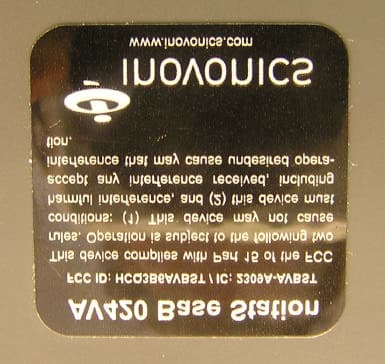
Click to zoom
Application Details
- Equipment Class
- DXX - Part 15 Low Power Communication Device Transmitter
- Date of Grant
- Oct 07, 2010
- Application Purpose
- Original Equipment
- Date of Application
- Aug 31, 2010
- Equipment Note
- ANALOG VOICE BASE STATION
- Frequency Range
- 922.80000000 - 927.60000000
- Country
- United States
Documents & Files
Document Text
Text extracted from the exhibit documents filed with the FCC. Open a document above to read the original.
Users Manual
1 QSR Performance Solutions Drive Thru System - Operating Instructions Batteries and Battery Charger • Be sure batteries are charged • Batteries take 2 to 3 hours to charge • A charge battery will last 8 to 10 hours • When the battery voltage becomes too low, a short warble tone, occurring at five–second intervals is heard in the headset. After 2 minutes the headset will shut off. • Batteries only fit into charge one way, the correct way • Charging indicator on charger will light red while battery is charging • Charging indicator on charger will change from red to green when battery is fully charge • Batteries should be left in charger even after they are fully charged • Batteries should be removed from belt-pack and stored in charger when belt-pack is not being used • Batteries not being used should stored in the charger Charging Indicators Charging Ports for Batteries Battery Charger Installing and Removing Batteries from Belt-Pack • Insert battery into battery compartment on belt-pack so it locks into place • Battery will only fully insert into battery compartment the correct way • To remove battery, slide battery release away from battery Battery Compartment Battery Release 2 QSR Performance Solutions Drive Thru System - Operating Instructions Connecting Headset to Belt-Pack • The 2 prong headset connector plugs into the bottom of the belt-pack Headset Jack Programming the Belt-Packs • Belt-packs must me programmed to the base station before they will operate properly • Programming station should already be plugged into base station • Make sure power indicator on base station is lit • Insert battery in belt-pack • Make sure belt-pack power is turned OFF • Insert belt-pack into programming station • Turn belt-pack power ON • Power indicator on belt-pack will flash green during programming (about 5 seconds) Programming Station Belt-Pack in Programming Station 3 QSR Performance Solutions Drive Thru System - Operating Instructions Taking Orders • Belt-pack should be in pouch and clipped to belt or waist-band on pants • Headset cable should be clipped near waist and near collar • Headset should be worn on head • The headband is adjustable • Make sure power indicator on belt-pack is lit green • When a car arrives at the menu-board, fast double beep will be heard every 3 seconds • Press the talk button on the belt-pack to talk to the customer For information on all of the features of the belt-pack, see the last page of these instructions. QSR Performance Solutions Drive Thru System - Base Station Front Cover Indicators & Controls Channel Indicators Page Indicator Talk Indicator Power Switch Used to turn power to Power Indicator Lights when Day / Night Volume Switch Grill Monitor Vehicle Indica- 4 QSR Performance Solutions Drive Thru - Belt-Pack 1 2 3 4 5 6 7 8 9 10 11 Bottom View 7. Talk 2 • Has the exact same function as Talk 1 when used with a single lane system • On Dual and Cross Lane systems Talk 2 will be programmed to communicate with Lane 2 8. Talk 1 • Activates communication to outside speaker • Will also be heard by other headsets and possibly grill speaker (depending on system configuration) • Can be used to test incoming and outgoing audio even when no car is present • On half-duplex systems, press to talk and release to listen • On full-duplex systems incoming audio will be heard even while Talk 1 is pressed • On Dual and Cross Lane systems Talk 1 will be programmed to communicate with Lane 1 9. Headset Jack • The 2 prong headset connector plugs in here 10. Battery Compartment • Battery goes here 11. Battery Release • Slide back to release battery from compartment 1. Page • Press to talk to the other headsets without being heard at the speaker post • Belt-packs can be programmed for Page Monitor Mode, they will only hear communication from other belt-packs that are using the Page button and will not hear communication to or from the speaker post • To program a belt-pack for Page Monitor Mode, hold Page button down while powering the headset on. • To exit Page Monitor Mode turn the belt-pack off and back on 2. Volume Down • Listening volume can be adjusted in 7 steps from the lowest to high- est setting. When the belt-pack is powered on, the listening level will be near mid-level and can be adjusted 3 steps up or 4 steps down. A short tone will be heard each time the volume is adjusted. A long tone is heard when the lowest or highest level is reached. 3. Volume Up • Turns up incoming audio from speaker post. See previous section for details 4. Power LED • Green when belt-pack is powered on • Red when talk-lock is in use • Flashes green during channel programming 5. Power On / Off • Press to turn power to belt-pack on or off 6. Talk Lock • Used with a full-duplex system, press to activate hands-free com- munication • When car arrives at speaker post, press to activate. Communication will automatically deactivate when car leaves speaker post and automatically reactivate when next car arrives • Press Talk 1 or Page to deactivate Talk Lock • Only 1 belt-pack at a time can use Talk Lock and no other headsets can talk to the speaker post • Disabled or enabled by holding Talk Lock button down when the headset is being powered up
Cover Letter(s)
August 5, 2010 Federal Communications Commission Authorization and Standards Division 7435 Oakland Mills Road Columbia, MD 21046 Subject: Request for Confidentiality for FCC ID# HCQ3B6AVBST Gentlemen: The following documents being submitted with the Application for Equipment Authorization for FCC ID# HCQ3B6AVBST are marked “Confidential”. We request that you maintain these documents in the non-public file and withhold them from public inspection, pursuant to Sections 0.457(d) and 0.459 of the Commission’s Rules, and Section 552(b)(4) of the Freedom of Information Act. This confidentiality is necessary to protect proprietary information, and falls under the category of “Trade Secrets”. 1) Operational Description 2) Schematics 3) Block Diagram Thanks for your help. Sincerely, Keal Vigil Production Control Specialist II Inovonics Wireless Corp. 303-209-7113 [email protected]
External Photos
FCC ID: HCQ3B6AVBST AV420 IC ID: 2309A-AVBST Page 1 External Photos: Front of AV420 Base Station (See page 2 for picture of back of product) FCC ID: HCQ3B6AVBST AV420 IC ID: 2309A-AVBST Page 2 Back of AV420 showing FCC & IC ID Numbers.
ID Label/Location Info
CONFIDENTIAL DOCUMENT LBL-FCC-AV420 05898A CONFIDENTIAL DOCUMENTATION The information contained in this document is confidential to and the sole property of Inovonics Corporation. Receipt of this information requires the existence and full acceptance of the terms and conditions of a Non Disclosure Agreement signed by the Inovonics Corporation and the Recipient. This documentation is not to be reproduced or redistributed except as provided in the Non Disclosure Agreement. Rev. Level DescriptionDate AInitial Release03/12/2010 © Inovonics 2010 MATERIAL:.002" THICK WHITE MYLAR WITH BLACK REVERSE COLOR AND .001" GLOSSY LAMINATION (FOR PROTECTION FROM INK SMEARING) AND PERMANENT ADHESIVE APPLIED TO THE BACKSIDE. RoHS COMPLIANT MATERIALS REQUIRED. ARTWORK:SUPPLIED BY INOVONICS. TEXT: WHITE. LABEL SIZE: 1.062" X 1.062" (SHOWN TO 3 TIMES SCALE) WITH .125 RADIUS ON EACH CORNER AND NO BORDER. PACKAGING AND LABEL ORIENTATION:LABELS TO BE SUPPLIED ON TOP SIDE OF ROLL STOCK WITH TEXT READABLE AS VIEWED FROM BOTTOM (SHORT) EDGE OF ROLL. AV420 Base Station This device complies with Part 15 of the FCC rules. Operation is subject to the following two conditions: (1) This device may not cause harmful interference, and (2) this device must accept any interference received, including interference that may cause undesired opera- tion. FCC ID: HCQ3B6AVBST / IC: 2309A-AVBST www.inovonics.com
ID Label/Location Info
FCC ID: HCQ3B6AVBST AV420 IC ID: 2309A-AVBST Page 1 External Photos: Front of AV420 Base Station (See page 2 for picture of back of product) FCC ID: HCQ3B6AVBST AV420 IC ID: 2309A-AVBST Page 2 Back of AV420 showing FCC & IC ID Numbers.
Internal Photos
FCC ID: HCQ3B6AVBST AV420 IC ID: 2309A-AVBST Page 1 Internal Photos: PCB FRONT PCB BACK
Test Report
This report is for the exclusive use of Intertek's Client and is provided pursuant to the agreement between Intertek and its Client. Intertek's responsibility and liability are limited to the terms and conditions of the agreement. Intertek assumes no liability to any party, other than to the Client in accordance with the agreement, for any loss, expense or damage occasioned by the use of this report. Only the Client is authorized to permit copying or distribution of this report and then only in its entirety. Any use of the Intertek name or one of its marks for the sale or advertisement of the tested material, product or service must first be approved in writing by Intertek. The observations and test results in this report are relevant only to the sample tested. This report by itself does not imply that the material, product, or service is or has ever been under an Intertek certification program. EMC Report for Inovonics on the Model: AV420 Page 1 of 21 TEST REPORT – EMC Emissions Report Number: 100115937DEN-002B Project Number: 100115937 Report Issue Date: 6/23/2010 Product Designation: Model: AV420 Standards: FCC CFR47 Part 15, Subpart C FCC Part 15.249 IC RSS-210e Issue 7: 2007 IC RSS-GEN Issue 2: 2007 Tested by: Client: Intertek Testing Services NA, Inc. 1795 Dogwood Street, Suite 200 Louisville, CO 80027 Emissions Testing Facility 40 Meadow Rd Pinewood Springs, CO 80540 Inovonics Wireless Corporation 315 CTC Blvd. Louisville, CO 80027 Report prepared by Report reviewed by Randy Thompson Senior EMC Project Engineer Michael Spataro Engineering Team Leader Intertek Report Number: 100115937DEN-002B Issued: 6/23/2010 EMC Report for Inovonics on the Model: AV420 Page 2 of 21 TABLE OF CONTENTS Section Page 1 Introduction and Conclusion .............................................................................................................. 4 2 Test Summary ...................................................................................................................................... 4 3 Description of Equipment Under Test................................................................................................ 6 4 System setup including cable interconnection details, support equipment and simplified block diagram ........................................................................................................................................................ 7 5 Radiated Emissions – Intentional: Field Strength of the Fundamental & Harmonics of the Fundamental ................................................................................................................................................ 9 6 AC Conducted Emissions – Not applicable to this test report ...................................................... 19 7 Measurement Uncertainty ................................................................................................................. 20 8 Revision History................................................................................................................................. 21 Intertek Report Number: 100115937DEN-002B Issued: 6/23/2010 EMC Report for Inovonics on the Model: AV420 Page 3 of 21 Product Under Test Model: AV420 (Quasar Base Station) Intertek Report Number: 100115937DEN-002B Issued: 6/23/2010 EMC Report for Inovonics on the Model: AV420 Page 4 of 21 1 Introduction and Conclusion The tests indicated in section 2.0 were performed on the product constructed as described in section 3.0. The remaining test sections are the verbatim text from the actual data sheets used during the investigation. These test sections include the test name, the specified test Method, a list of the actual Test Equipment Used, documentation Photos, Results and raw Data. No additions, deviations, or exclusions have been made from the standard(s) unless specifically noted. Based on the results of our investigation, we have concluded the product tested complies with the requirements of the standard(s) indicated. The results obtained in this test report pertain only to the item(s) tested. 2 Test Summary Section Test full name Test date Result 5 Radiated Emissions – Intentional per FCC Part 15.249(a) (Covers IC RSS-210: Annex 2.9(a) 05/14/10 Pass 6 Conducted Emissions – ----- ----- Notes: 1. Only Intentional Radiated Emissions was tested and listed in this report per client request. Unintentional Radiated Emissions and Conducted Emissions for this product was also tested and passed. Please refer to Report Number: 100115937DEN-001. Intertek Report Number: 100115937DEN-002B Issued: 6/23/2010 EMC Report for Inovonics on the Model: AV420 Page 5 of 21 General Remarks for Radio Testing: The following remarks are to be considered as “where applicable” and are taken into account while completing any FCC/IC/ETSI Radio tests at Intertek-Louisville. Testing was performed in 3 different orthogonal axes to determine the worst-case emissions from the device. The worst-case emissions are shown in this report. FCC CFR47 Part 15.31: Measurement Standards: In any case where the device is powered off a battery, a fresh battery was used during testing. In cases where the device is powered of an AC Supply, voltage was varied per Part 15.31 to find worst-case emissions. FCC CFR Part 15.35: Measurement Detector Functions and Bandwidths: FCC Part 15.35 was utilized when performing measurements within this report. The testing performed in accordance to FCC CFR47 Part 15.205 (restricted bands of operation) and Part 15.249 emissions and delta limits were calculated as follows: Final Corrected Peak Measurement – Duty Cycle Correction Factor* = Final Calculated Emission The Final Calculated Emission was then compared to the Limits in CFR47 Part 15.209 and Part 15.249 and the emission/limit delta was calculated. When applicable, the “Duty Cycle Correction Factor” (DTCF) is calculated as follows: 20*Log 10 (duty cycle in 100ms) “not to exceed 20 dB ” If the antenna is externa…
Text truncated - open the document above for the full version.
Test Report
This report is for the exclusive use of Intertek's Client and is provided pursuant to the agreement between Intertek and its Client. Intertek's responsibility and liability are limited to the terms and conditions of the agreement. Intertek assumes no liability to any party, other than to the Client in accordance with the agreement, for any loss, expense or damage occasioned by the use of this report. Only the Client is authorized to permit copying or distribution of this report and then only in its entirety. Any use of the Intertek name or one of its marks for the sale or advertisement of the tested material, product or service must first be approved in writing by Intertek. The observations and test results in this report are relevant only to the sample tested. This report by itself does not imply that the material, product, or service is or has ever been under an Intertek certification program. EMC Report for Inovonics on the AV120, AV220, AV420 & EN7286NX Page 1 of 30 TEST REPORT – EMC Emissions Report Number: 100115937DEN-001 Project Number: 100115937 Report Issue Date: 05/29/2010 Product Designation: Models: AV120, AV220, AV420 & EN7286NX Standards: IEC CISPR 22: 2008 FCC CFR47 Part 15, Subpart B: 2007 ICES-003, Issue 4: 2004 AS/NZS CISPR 22: 2006 Tested by: Client: Intertek Testing Services NA, Inc. 1795 Dogwood Street, Suite 200 Louisville, CO 80027 Emissions Testing Facility 40 Meadow Rd Pinewood Springs, CO 80540 Inovonics Wireless Corporation 315 CTC Blvd. Louisville, CO 80027 Report prepared by Report reviewed by Randy Thompson Senior EMC Project Engineer Richard Georgerian Senior Project Engineer Intertek Report Number: 100115937DEN-001 Issued: 05/28/2010 EMC Report for Inovonics on the AV120, AV220, AV420 & EN7286NX Page 2 of 30 TABLE OF CONTENTS Section Page 1 Introduction and Conclusion .............................................................................................................. 6 2 Test Summary ...................................................................................................................................... 6 3 Description of Equipment Under Test................................................................................................ 7 4 System setup including cable interconnection details, support equipment and simplified block diagram ........................................................................................................................................................ 8 5 Radiated Emissions – Unintentional & Spurious of the Receiver ................................................. 12 6 DC Conducted Emissions ................................................................................................................. 22 7 Measurement Uncertainty ................................................................................................................. 29 8 Revision History................................................................................................................................. 30 Intertek Report Number: 100115937DEN-001 Issued: 05/28/2010 EMC Report for Inovonics on the AV120, AV220, AV420 & EN7286NX Page 3 of 30 Product Under Test Model: AV120 (Headset Transceiver) Intertek Report Number: 100115937DEN-001 Issued: 05/28/2010 EMC Report for Inovonics on the AV120, AV220, AV420 & EN7286NX Page 4 of 30 Product Under Test Model: AV420 (Base Station Transceiver with AV220 attached) Intertek Report Number: 100115937DEN-001 Issued: 05/28/2010 EMC Report for Inovonics on the AV120, AV220, AV420 & EN7286NX Page 5 of 30 Product Under Test Model: EN7286NX (Serial Receiver with control panel interface) Intertek Report Number: 100115937DEN-001 Issued: 05/28/2010 EMC Report for Inovonics on the AV120, AV220, AV420 & EN7286NX Page 6 of 30 1 Introduction and Conclusion The tests indicated in section 2.0 were performed on the product constructed as described in section 3.0. The remaining test sections are the verbatim text from the actual data sheets used during the investigation. These test sections include the test name, the specified test Method, a list of the actual Test Equipment Used, documentation Photos, Results and raw Data. No additions, deviations, or exclusions have been made from the standard(s) unless specifically noted. Based on the results of our investigation, we have concluded the product tested complies with the requirements of the standard(s) indicated. The results obtained in this test report pertain only to the item(s) tested. 2 Test Summary Section Test full name Test date Result 5 Radiated Emissions – Unintentional per CISPR 22, Class B (Covers FCC CFR47 Part 15B, AS/NZS CISPR 22 & ICES-003) 05/12/10 Pass 6 DC Conducted Emissions – per CISPR 22, Class B (Covers FCC CFR47 Part 15B, AS/NZS CISPR 22 & ICES-003) 05/12/10 Pass Notes: 1. Only unintentional radiated emissions were tested per client request. 2. The client has stated Inovonics products are not shipped with an AC Adapter power supply. Therefore, conducted emissions were tested with 12-14 VDC supplied to the product. 3. Products were “bundled” together and tested simultaneously for radiated emissions testing per client request. Intertek Report Number: 100115937DEN-001 Issued: 05/28/2010 EMC Report for Inovonics on the AV120, AV220, AV420 & EN7286NX Page 7 of 30 3 Description of Equipment Under Test Equipment Under Test Description Manufacturer Model Number Serial Number Headset Transceiver Inovonics AV120 EMC1 Programmer Inovonics AV220 EMC1 Base Station Transceiver Inovonics AV420 16594719 Serial Receiver with control panel interface Inovonics EN7286NX 16479943 Receive Date: 05/12/2010 Received Condition: Good Type: Production Proto Description of Equipment Under Test (provided by client) The following products were tested in this report: 1. EN7286NX Serial Receiver with control panel interface 2. AV120 Headset Transceiver 3. AV220 Programmer 4. AV420 Base Station Transceiver Products are intended to be used in off…
Text truncated - open the document above for the full version.
Test Report
FCC ID: HCQ3B6AVBST IC ID: 2309A-AVBST 07/29/2010 Proof of AV420 Compliance with MPE RF Limits The AV420 complies with the general population MPE RF limits by a compliance margin factor of more than 1000. Proof As shown in the enclosed EMC Emissions Test Report, the AV420 was tested to comply with CFR 47, Part 15.249 for fundamental transmission frequencies in the range of 902 – 928 MHz. Proving AV420 compliance with MPE limits will be achieved by proving that any fixed-location continuous-carrier transmitter, that is within this frequency range and that passes this regulation, will likewise pass the MPE limits. Then, AV420 compliance is inferred by simple deductive reasoning. 1. Referring to 15.249, a transmitter’s maximum fundamental-frequency field strength permitted at a distance of three meters in the 902 – 928 MHz band is 50 mV/m. Assume that the transmitter is an isotropic radiator and that the field strength at a distance of 20 cm is dominated by the 1/r far-field radiation component. The 20 cm distance was chosen because this is the distance at which MPE limits are measured for mobile transmitters per 2.1091. Since the 420 is a fixed-location device that is typically mounted on a wall, achieving MPE compliance at 20 cm would be achieving compliance under a worst-case criterion. Maximum field strength at 20 cm is determined by E 20cm = E 3m (3 / 0.2) = 50 mV/m (15) = 0.750 V/m This field strength is then converted to power density by P 20cm = (E 20cm ) 2 / 377 = (0.750) 2 / 377 = 1.49 mW/m 2 = 0.000149 mW/cm 2 2. In the frequency range of 902 – 928 MHz, the MPE limit per 1.1310 for the general population is given by the formula P MPE limit = (f / 1500) mW/cm 2 where f is in the range of 902 to 928 MHz 3. Taking the worst-case transmitter frequency of 902 MHz, the MPE limit is calculated by P MPE limit = (902 / 1500) mW/cm 2 = 0.601 mW/cm 2 4. Clearly, all fixed-location, continuous-carrier transmitters in the 902 – 928 MHz operating range that comply with 15.249 will comply with this worst-case MPE limit. Since the AV420 is one of these transmitter types, it also complies. Additional FCC ID: HCQ3B6AVBST IC ID: 2309A-AVBST 07/29/2010 calculation refinements due to the isotropic and far-field 1/r radiation assumptions are not warranted since the compliance margin is so great.
Test Setup Photos
Intertek Report Number: 100115937DEN-002B Issued: 6/23/2010 EMC Report for Inovonics on the Model: AV420 Page 3 of 21 Product Under Test Model: AV420 (Quasar Base Station) Intertek Report Number: 100115937DEN-002B Issued: 6/23/2010 EMC Report for Inovonics on the Model: AV420 Page 10 of 21 5.4 Setup Photographs: Radiated Emissions Test setup – Front View Intertek Report Number: 100115937DEN-002B Issued: 6/23/2010 EMC Report for Inovonics on the Model: AV420 Page 11 of 21 Photo: Radiated Emissions Test setup – Rear View Intertek Report Number: 100115937DEN-002B Issued: 6/23/2010 EMC Report for Inovonics on the Model: AV420 Page 12 of 21 Photo: Test setup – Axis 1 (EUT Flat on Table) Intertek Report Number: 100115937DEN-002B Issued: 6/23/2010 EMC Report for Inovonics on the Model: AV420 Page 13 of 21 Photo: Test setup – Axis 2 (EUT Vertical) Intertek Report Number: 100115937DEN-002B Issued: 6/23/2010 EMC Report for Inovonics on the Model: AV420 Page 14 of 21 Photo: Test setup – Axis 3 (EUT Vertical & Rotated 90 Degrees) Note: Axis 3 was determined to be worst-case
Test Setup Photos
Intertek Report Number: 100115937DEN-001 Issued: 05/28/2010 EMC Report for Inovonics on the AV120, AV220, AV420 & EN7286NX Page 3 of 30 Product Under Test Model: AV120 (Headset Transceiver) Intertek Report Number: 100115937DEN-001 Issued: 05/28/2010 EMC Report for Inovonics on the AV120, AV220, AV420 & EN7286NX Page 4 of 30 Product Under Test Model: AV420 (Base Station Transceiver with AV220 attached) Intertek Report Number: 100115937DEN-001 Issued: 05/28/2010 EMC Report for Inovonics on the AV120, AV220, AV420 & EN7286NXPage 13 of 30 5.4 Setup Photographs: Test setup – Front View Left-to-Right: AV120, EN7286NX, AV420 (with AV220 attached) & AV120 Intertek Report Number: 100115937DEN-001 Issued: 05/28/2010 EMC Report for Inovonics on the AV120, AV220, AV420 & EN7286NXPage 14 of 30 Test setup – Rear View Intertek Report Number: 100115937DEN-001 Issued: 05/28/2010 EMC Report for Inovonics on the AV120, AV220, AV420 & EN7286NXPage 25 of 30 Photo: Test setup – AV420 Front View Intertek Report Number: 100115937DEN-001 Issued: 05/28/2010 EMC Report for Inovonics on the AV120, AV220, AV420 & EN7286NXPage 26 of 30 Photo: Test setup – AV420 Side View
Contact Information
Applicant
Jess Cobb(Manager of Program Mgmt)
Technical Contact
Inovonics Wireless CorpDaryl Burkhard
[email protected]303-209-7145
315 CTC Blvd · Louisville, Colorado · United States
Non-Technical Contact
Inovonics Wireless CorpKeal Vigil
[email protected]303-209-7113
Test Firm
Intertek Testing Services NA, Inc.Jay Kogoma
Technical Specifications
| # | Rule Parts | Frequency Range | Power Output |
|---|---|---|---|
| 1 | 15C | 922.8 MHz - 927.6 MHz | - |
Other Applications from Inovonics Wireless Corporation

HCQ-IDTOUCH1
May 13, 2026Inovonics Wired Touchscreen Keypad
Equipment Class
DTS - Digital Transmission System
HCQBWA02
Aug 28, 2024Flush Mount Locator
Equipment Class
DSS - Part 15 Spread Spectrum Transmitter
HCQTBA
Sep 21, 2022TBA Module
Equipment Class
DSS - Part 15 Spread Spectrum Transmitter
HCQPFA01
Jul 14, 2022Fall Detect Transmitter
Equipment Class
DSS - Part 15 Spread Spectrum Transmitter
HCQ3B6BRGSA
Sep 22, 2020Bluetooth to EchoStream Bridge
Equipment Class
DTS - Digital Transmission System