HCQ3B6ECNCAPortable Alarm System
Inovonics Wireless Corporation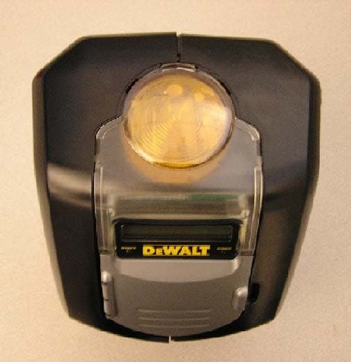
Click to zoom
Application Details
- Equipment Class
- DSS - Part 15 Spread Spectrum Transmitter
- Date of Grant
- Dec 02, 2004
- Application Purpose
- Original Equipment
- Date of Application
- Oct 17, 2004
- Equipment Note
- Portable Alarm System
- Frequency Range
- 902.00000000 - 928.00000000
- Country
- United States
Documents & Files
Document Text
Text extracted from the exhibit documents filed with the FCC. Open a document above to read the original.
Users Manual
DS100 JobSite Security Portable Alarm System (Base Unit)Système d'alarme mobile de sécurité des chantiers DS100 (Base)Sistema de Alarma Portátil JobSite Security DS100 (unidad base)INSTRUCTION MANUALGUIDE D’UTILISATIONMANUAL DE INSTRUCCIONES INSTRUCTIVO DE OPERACIÓN, CENTROS DE SERVICIO Y PÓLIZADE GARANTÍA. ADVERTENCIA: LÉASE ESTE INSTRUCTIVO ANTES DE USAR EL PRODUCTO. Questions? See us on the World Wide Web at www.dewalt.com Before returning this product call 1-800-4-D E WALT IF YOU SHOULD EXPERIENCE A PROBLEM WITH YOUR DEWALT PURCHASE, CALL 1-800-4 DEWALT IN MOST CASES, A D E WALT REPRESENTATIVE CAN RESOLVE YOUR PROBLEM OVER THE PHONE. IF YOU HAVE A SUGGESTION OR COMMENT, GIVE US A CALL. YOUR FEEDBACK IS VITAL TO THE SUCCESS OF D E WALT’S QUALITY IMPROVEMENT PROGRAM. i IF YOU HAVE ANY QUESTIONS OR COMMENTS ABOUT THIS OR ANY D E WALT TOOL, CALL US TOLL FREE AT: 1-800-4-D E WALT (1-800-433-9258) LCD DISPLAY FUNCTION LEDs FUNCTION LEDs KEYPAD INTERFACE VIBRATION SENSOR MOTION SENSOR PHONE LINE BACK-UP 8-HOUR BATTERY BACK-UP AC ADAPTER WIRELESS SENSORS RECEIVER- TRANSMITTER CELLULAR RADIO RECEIVER- TRANSMITTER STROBE LIGHT RESET BUTTON BATTERY SIREN DS100 DS200 UNLOCK LOCK CARABINER FIG. 1 English ii Table of Contents Introduction......................................................................................................iii Safety and Precautionary Information ....................................................iiiLimitations of the System ......................................................................iiiRegulatory and Safety Notices ..............................................................iv Product Overview ............................................................................................1 Unique Features ......................................................................................1 Cellemetry®......................................................................................1900 MHz, Frequency Hopping Spread Spectrum ..........................1 System Overview ............................................................................................1 DS100 Base Unit ....................................................................................1Accessories ..............................................................................................2Prevention of False Alarms......................................................................2During an Alarm ......................................................................................2 Initial Setup ......................................................................................................3 Connecting the Equipment ......................................................................3 Placement of the Base Unit ............................................................3Power and Telephone Connection ..................................................3 Programming for Initial Setup ..................................................................4 Step One: Choosing a Language ....................................................4Step Two: Set Time and Date ..........................................................4Step Three: Set Master Code ..........................................................4Step Four: Assign Devices ..............................................................5Step Five: Test Range......................................................................6Step Six: Add Users ........................................................................6Step Seven: Monitoring Service ......................................................7 Basic Operations ............................................................................................7 Arming the System ..................................................................................7 Delays ..............................................................................................7Using the Keypad ............................................................................7Using the Key Chain Remote ..........................................................7Arming Automatically........................................................................8 Disarming the System..............................................................................8 Entry Delays ....................................................................................9Using the Keypad ............................................................................9Using the Key Chain Remote ..........................................................9 Faults........................................................................................................9 How to View Faults ..........................................................................9Clearing a Fault ................................................................................9Description of Fault Codes ............................................................10 Features & Options ......................................................................................10 System Settings ....................................................................................10 Wireless Device Maintenance ......................................................10Change Master Code ....................................................................11User Code Maintenance ................................................................12Set Console Devices......................................................................13Set Delay/Instant ............................................................................13Clear Settings ................................................................................14Auto Arm ON/OFF..........................................................................14Auto Arm Time Set ........................................................................15Review Account........................................…
Text truncated - open the document above for the full version.
Users Manual
Features & Options 14 4. Use the up and down arrows to scroll through the menu until the System Settings screen is displayed. Select OK. 5. Use the up and down arrows to scroll through the menu until the Set Delay/Instant screen is displayed. Select OK. 6. Using the up and down arrows, scroll through the list of programmed devices. The screen will indicate whether the device is currently set on delay or instant. 7. When the device to be changed is reached, select CHANGE. The CHANGE button toggles between delay and instant. 8. After changing each device, select EXIT to go back to the main screen. CLEAR SETTINGSNOTE: This function will free the Base Unit to be completely reprogrammed. This system has been designed to be portable. If the site location changes and users, sen-sor descriptions and locations need to be changed, the system can clear the current set-tings. All registered sensors and users will be deleted from the system. The master codewill NOT be deleted. NOTE: If changing locations will result in the unit being disconnected from the wall outlet for more than 8 hours, place the unit in the standby state. This will preserve battery life andprotect the Base Unit. See Turning System Off . 1. Start at the main screen.2. Select MENU or press MAIN MENU on the keypad.3. Using the keypad, enter the master code.4. Use the up and down arrows to scroll through the menu until the System Settings menu is displayed. Select OK. 5. Use the up and down arrows to scroll through the menu until the Clear Settings screen is displayed. Select OK. 6. Enter the master code.7. The system will request one final check before clearing the settings. All registered sen- sors, sirens, Key Chain Remotes, and users will be deleted from the system. To sim-ply change sensor descriptions, user names or user codes use the System Settingsmenu instead. To confirm a clearing of the settings, select YES.See Programming for Initial Setup for instructions on adding sensors and users. Be sure to contact the monitoring service to notify them of the changes. AUTO ARM ON/OFF The system can be set to arm at a particular time each day. This feature can be useful toensure the system can be properly armed if arming cannot be initiated by the master useror other users of the system. CAUTION: LOUD NOISE. Enabling the auto arm feature will cause a brief, loud noise while arming that may startle any persons near the Base Unit. 1. Start at the main screen.2. Select MENU or press MAIN MENU on the keypad.3. Using the keypad, enter the master code.4. Use the up and down arrows to scroll through the menu until the System Settings screen is displayed. Select OK. 5. Use the up and down arrows to scroll through the menu until the Auto Arm ON/OFF screen is displayed. Select OK. 6. When the Autoarm OFF screen appears, select CHANGE. The CHANGE button toggles between off and on. English 15 7. When the automatic arming is enabled, the Autoarm ON screen will appear. Select EXIT.IMPORTANT: If a user disarms the system after the auto arm time and still requires protection, the user will need to re-arm the system using the Key Chain Remote or key-pad. The following day, the auto arm will continue to auto arm at the pre-set time. AUTO ARM TIME SETThe system can be set to arm at a particular time each day. To set or change the time ofautomatic arming, follow these steps. 1. Start at the main screen.2. Select MENU or press MAIN MENU on the keypad.3. Using the keypad, enter the master code.4. Use the up and down arrows to scroll through the menu until the System Settings screen is displayed. Select OK. 5. Use the up and down arrows to scroll through the menu until the Set Auto Arm Time screen is displayed. To set the time, select OK. 6. Using the numbers on the keypad, choose the time the system is to be automatically armed, changing hours first and then minutes. The character that is being changed willbe underlined. To move back a character, use the down arrow. To move forward a char-acter, use the up arrow. Select SET. 7. Choose AM or PM. Use the up and down arrows to toggle between AM and PM. Select SET. REVIEW ACCOUNT The user is able to view the account information directly from the Base Unit. This includescontact numbers, the account number, and the mobile identification number. • Customer Service Information • Account Number • MIN – Mobile Identification Number 1. Start at the main screen.2. Select MENU or press MAIN MENU on the keypad.3. Using the keypad, enter the master code.4. Use the up and down arrows to scroll through the menu until the System Settings screen is displayed. Select OK. 5. Use the up and down arrows to scroll through the menu until the Review Account screen is displayed. Select OK. Customer Service informationNOTE: To activate the monitoring of this system, contact customer service.To View Account Number Use the up and down arrows to scroll through the menu until the Account Numberscreen is displayed. This screen will display the account number. This number is impor-tant to provide to customer service. To exit this screen, select EXIT. To View the Mobile Identification Number (MIN) Use the up and down arrows to scroll through the menu until the MIN screen is dis-played. This screen will display the Mobile Identification Number. This number is impor-tant to provide to customer service. To exit this screen, select EXIT. Features & Options 16 CHOOSE LANGUAGE Choose from three different languages (English, Spanish and French) for the LCD screen. 1. Start at the main screen.2. Select MENU or press MAIN MENU on the keypad.3. Using the keypad, enter the master code.4. Use the up and down arrows to scroll through the menu until the System Settings menu is displayed. Select OK. 5. Use the up and down arrows to scroll through the menu until the Choose Language screen is displayed. Select OK. 6. To continue in English, select OK. 7. To choose another language, use the arrow keys to find the correct language. When the desired language i…
Text truncated - open the document above for the full version.
Users Manual
34 Configuration initiale 1. Connecter la fiche (A) du bloc d’alimentation à la prise (B) à l’arrière de la base (C).2. Insérer la fiche de 120v du bloc d’alimentation (D) dans la prise murale.3. Le voyant d’alimentation indiquera que le système est alimenté. IMPORTANT : Une fois l’appareil branché, le système d’alarme ne sera actif qu’une fois la configuration initiale terminée, les détecteurs programmés, et que le serviceclientèle D E WALT aura enregistré le système. Connexion téléphonique REMARQUE : La connexion téléphonique sert de source de communication de secours. En cas de perte de connexion de la radio cellulaire (voyant DEL éteint), laconnexion téléphonique sera utilisée. MISE EN GARDE : Pour prévenir tout dommage au système, utiliser un para- surtenseur pour communications téléphoniques. 1. Connecter la prise téléphonique (E) dans le jack (F) à l’arrière de la base (C).2. Insérer l’autre bout du fil téléphonique dans le jack modulaire mural. Ne pas utiliser un jack modulaire relié à des lignes multiples comme pour les systèmestéléphoniques où différents numéros de téléphone sonnent sur un téléphone unique.Ce système ne fonctionnera pas sur un téléphone payant. Programmation de la configuration initialeUne fois la base alimentée en courant, une séquence de configuration permettra depersonnaliser le système.SEPT ÉTAPES FACILES : 1. Choix de la langue 2. Réglage de l’heure et de la date 3. Configuration du code maître 4. Assignation des dispositifs (avoir à portée de main télécommande porte-clés et détecteurs et piles) 5. Test de portée 6. Addition d’utilisateurs 7. Service de surveillance ÉTAPE UN : CHOIX DE LA LANGUE Choisir entre trois langues différentes : Anglais, Français ou Espagnol.Une langue sera affichée sur l’écran lorsque la base sera alimentée en courant. E F C A B C D 1. Pour continuer en Anglais, choisir OK.2. Pour choisir une autre langue, utiliser les flèches pour trouver la langue voulue.3. Lorsque la langue voulue est affichée, choisir OK. ÉTAPE DEUX : RÉGLAGE DE L’HEURE ET DE LA DATE L’heure et la date DOIVENT être réglées lors de la configuration initiale. Le rapport d’activitésaffichera les évènements suivant la date et l’heure. 1. À l’aide des chiffres du clavier, régler l’horloge à l’heure appropriée, en changeant tout d’abord les heures, puis les minutes. Le caractère qui sera changé sera souligné. Pourreculer d’un caractère, utiliser la flèche vers le bas. Pour avancer d’un caractère, utiliserla flèche vers le haut. Choisir CONFIG. 2. Choisir AM ou PM (Matin ou Soir). Les flèches vers le haut ou le bas sont utilisées pour passer de AM à PM. Choisir CONFIG. 3. À l’aide des chiffres du clavier, régler la date. Le caractère qui sera changé sera souligné. Pour reculer d’un caractère, utiliser la flèche vers le bas. Pour avancer d’uncaractère, utiliser la flèche vers le haut. Choisir CONFIG. ÉTAPE TROIS : CONFIGURATION DU CODE MAÎTRE Un code maître DOIT être choisi. Ce code peut être changé. Ce code cependant est leSEUL qui peut être utilisé pour changer la programmation et annuler une erreur.L’écran Code maître s’affichera une fois la date configurée. Code maître : #### RET. < > OK DATE : 01/04/04RET. < > CONFIG 35 Français 1. À l’aide des chiffres du clavier, entrer un code maître à quatre chiffres. Le caractère qui sera changé sera souligné. Pour reculer d’un caractère, utiliser la flèche vers le bas.Pour avancer d’un caractère, utiliser la flèche vers le haut.REMARQUE : Seul le code maître peut être utilisé pour changer la programmation. S’assurer de choisir un code facile à se rappeler ou inscrire ce code dans un endroit sûret éloigné du système. En cas de perte du code maître, il faudra le réinitialiser auprèsdu service clientèle. Se reporter à la section En cas de perte du code maître pour plus de détails. Tous les autres utilisateurs n’auront accès qu’aux fonctions d’armement etde désarmement. Pour ajouter un nouvel utilisateur se reporter à la section Ajouter utilisateurs . 2. Une fois le code maître entré, choisir OK.3. Réentrer le code maître pour le confirmer. De la même façon, à l’aide des chiffres du clavier, entrer le code maître à quatre chiffres. Choisir OK. 4. Si les codes maître cadrent, l’écran indiquera que le code maître a été sauvegardé. Choisir SUIV.REMARQUE : Si les codes maître ne cadrent pas, l’écran affichera Code erroné. Si les codes maître ne cadrent pas, 1. Choisir OK.2. Réentrer le code maître. Choisir OK. 3. Si les codes maître cadrent, l’écran indiquera que le code maître a été sauvegardé.Choisir SUIV. ÉTAPE QUATRE : ASSIGNATION DES DISPOSITIFS Jusqu’à 48 détecteurs et 6 télécommandes porte-clés peuvent être assignés. Chaque foisqu’un détecteur sera ajouté, il communiquera avec la base pour aviser l’utilisateur de toute Code maître sauv. SUIV Code maître (bis): RET. < > OK Code erronéOK Code maître sauv. SUIV Code maître (bis): RET. < > OK intrusion. D’autres détecteurs et télécommandes peuvent être programmés à tout momentune fois la configuration initiale terminée. Se reporter à la section Entretien des dispositifs sans fils . REMARQUE : Chaque dispositif (télécommande porte-clés ou détecteurs) doit comporter des piles pour fonctionner. Se reporter au manuel d’instruction respectif à chaque dispositifpour déterminer le type de pile requis. 1. L’écran Assig dispositif mobile s’affichera une fois le code maître configuré. Pour ajouter détecteurs et télécommandes porte-clés, choisir OK. 2. Le numéro de dispositif du prochain dispositif libre sera affiché. Ajouter la télécommande porte-clés incluse avec la base en premier. Choisir OK. Le dispositifn’est pas enregistré tant que OK n’est pas sélectionné et que le bouton deréinitialisation des dispositifs n’a pas été poussé puis relâché. REMARQUE : Chaque dispositif possède un bouton de réinitialisation qui doit être poussé puis relâché. Pourtrouver ce bouton de réinitialisation, se référer auxinstructions spécifiques à chaque dispositif. 3. Réinitialiser le dispositif. MISE EN GA…
Text truncated - open the document above for the full version.
Users Manual
54 Appendice CLAVIER Appuyer 12 34 5 11111122ABC233DEF344GHI 455JKL566MNO677PQRS88TUV899WXYZ00 espace . espace . DIAGRAMME ALPHA/NUMÉRIQUE DESCRIPTION DES CODES D'ERREURS DEL CONTINU CLIGNOTANT ÉTEINT ALIMENTATION Source • Source d’alimentation Privé d’alimentation primaire absente d’alimentation primaire présente (clignote en continu) secteur et pile • Pile faible (par séries de deux clignotements) ou • État de veille (un clignotement toutes les 5 secondes) ARMÉ Le système est Pendant le délai d'entrée Le système armé ou de sortie est désarmé CELL Le signal cellulaire Le signal cellulaire Aucun signal et puissant et faible cellulaire APPEL Appel terminé Appel en cours Aucune restera allumé en activité continu pendant30 secondes) Code d’erreur Affichage Description Action Aliment Perte ali. princ./base Base privée d’alimentation Vérifier la source d’alimentation Ali/Disp Perte d’ali. princ/disp Dispositif privé d'alimentation Changer la pile, réinitialiser PileFaibBse Pile faible/base Pile de la base faible Brancher sur secteur pour recharger la pile Pilefaibdisp. Disp/pile faible Pile du dispositif faible Changer la pile, réinitialiser Signfaib Disp/signal faible La transmission du signal du dispositif est faible Éliminer toute interférence, déplacer le dispositif Suspect Disp. suspect Le dispositif a été déclenché Vérifier toute intrusion, réarmer le dispositif AucunValid. Aucun disp. validé Aucun message envoyé par le dispositif n’a été reçu Éliminer toute interférence, déplacer le dispositif Alt. Alt. Le dispositif a été ouvert ou endommagé Fermer le dispositif ou le remplacer si endommagé MauvPileBse Pile mauv/base Le voltage de la pile de la base est inférieur à la limite prescrite La base doit être rapportée chez un centre de service autorisé D E WALT pour entretien RadioCell Err Radio cell. Le signal cellulaire a été perdu Déplacer la base là où le voyant CELL restera allumé en continu Récepteur Err/ récepteur disp. # La transmission bi-directionnelle du dispositif a été perdue Appeler le service clientèle pour vérifier le système 55 Français DESCRIPTION DES CODES D'ÉVÈNEMENT Code d'évènement Description Action Base : 0 C.A. Base privée d'alimentation Vérifier la source d'alimentation Base : ALI. RESTAURÉE Alimentation de la baserestaurée NÉANT DISP x txt : PILE ABS L'alimentation pile du dispositifest inexistante Changer la pile, réinitialiser DISP x txt : ALI. RESTAURÉE L'alimentation du dispositif a étérestaurée NÉANT DISP x txt : PILE FAIB Pile du dispositif faible Changer la pile,réinitialiser le dispositif DISP x txt : PILE FAIB SUPP L'alimentation du dispositif a été restaurée NÉANT PILE FAIB/BASE Le voltage de la pile est inférieur à la limite prescrite Brancher sur secteurpour recharger la pile PILE FAIB/BASE SUPP La pile de la base a étérechargée NÉANT DISP x txt : SIGNAL FAIB La transmission du signal dudispositif est faible Vérifier toute interférence,déplacer le dispositif DISP x txt : BON SIGNAL La transmission du signal dudispositif est bonne maintenant NÉANT DISP x txt : SUSPECT Le dispositif a été déclenché Vérifier toute intrusion, réactiver le dispositif DISP x txt : SUSPECT SUPP Le dispositif a été réactivé NÉANT DISP x txt : ALT. Le dispositif a été ouvert ouendommagé Fermer le dispositif ou leremplacer si endommagé DISP x txt : NON VALIDÉ Aucun message du dispositif n'a été reçu Vérifier toute interférence,déplacer le dispositif DISP x txt : NON VALIDÉ SUPP Le message du dispositif a été reçu NÉANT DISP x txt : RÉINIT Le dispositif a été réinitialisé NÉANT DISP x txt : ENREGISTRÉ Le dispositif a été enregistré NÉANT DISP x txt : SUPP. Le dispositif a été désenregistréet éliminé de la configuration NÉANT Base : ERR PILE La pile du système estdéfectueuse Doit être réparée chez un centre de service autoriséDEWALT Base : ERR PILE SUPP La pile de la base a été rechargée NÉANT Mvmt base : ALERTE Détecteur de mouvements de labase a été déclenché Vérifier toute intrusion au niveaude la base Mvmt base : ALERTE SUPP L'alerte du détecteur demouvements de la base a été supprimée NÉANT Vibration/base : ALERTE Détecteur de vibrations de labase a été déclenché Vérifier toute intrusion au niveaude la base Vibration/base : ALERTE SUPP L'alerte du détecteur devibrations de la base a été supprimée NÉANT DESCRIPTION DES CODES D'ÉVÈNEMENT Code d'évènement Description Action Radio cell. : ARRÊT La radio cellulaire a été arrêtée Se reporter au Guide dedépannage, appeler le serviceclientèle Radio cell. : ACTIVÉ La radio cellulaire a été activée NÉANT UTIL. x txt : ARMÉ ou DISP x txt : ARMÉ Utilisateur x ou télécommandeporte-clés x a réarmé le système NÉANT UTIL. x txt : DÉSARMÉ ou DISP x txt : DÉSARMÉ Utilisateur x ou télécommandeporte-clés x a désarmé le système NÉANT UTIL. x txt : ARM. FORCÉ ouDISP x txt : ARM. FORCÉ Utilisateur x ou télécommandeporte-clés x a désarmé lesystème malgré une erreur Vérifier toute erreur, résoudre le problème, effacer l'erreur puisréarmer Base : AUTO-ARM Le système a étéautomatiquement armé NÉANT Base : AUTO-ARM FORCÉ Le système a étéautomatiquement armé malgréune erreur Vérifier toute erreur, résoudre leproblème, effacer l'erreur puisréarmer Base : CONNECTÉ Un appel a été placé auprès duservice de surveillance NÉANT Base : APL AVORTÉ L'appel au service de surveillance n'a pu être placé Appeler le service clientèle pourvérifier le système Sirène/base : ACTIVÉ ouStrobe/base : ACTIVÉ La sirène de la base ou lestroboscope a été activé NÉANT Sirène/base : DÉSACTIVÉ ouStrobe/base : DÉSACTIVÉ La sirène de la base ou lestroboscope a été désactivé NÉANT MODE MAÎTRE: L'utilisateur maître a entré le code maître NÉANT MODE MAÎTRE DÉL DÉP L'utilisateur maître a dépassé le temps alloué NÉANT QUIT MODE MAÎTRE L'utilisateur maître a quitté le mode maître NÉANT UTIL x : AJOUT L'utilisateur x a été ajouté ausystème NÉANT UTIL x : SUPP. L'utilisateur x a été supprimé du système NÉANT HEURE/DATE CHANGÉE L'utilisateur maître a modifiél'heure et/ou la date NÉANT ERR. EFF…
Text truncated - open the document above for the full version.
Users Manual
74 4. Reposicione el dispositivo. NOTA: Cada dispositivo tiene un botón de reposicionamiento que debe ser presionado y liberado. Para ubicar el botón de reposicionamiento, refiérase a las instrucciones decada dispositivo. Asegúrese de que cada dispositivo tenga pilas debidamenteinstaladas. Ahora, presione el botón de reposicionamiento. 5. La pantalla indicará que el dispositivo ha sido registrado. Sólo se pueden agregar 48 sensores y 6 controles remotos de llavero. Si ya no quedan más espacios vacantes, lapantalla dirá TODOS LOS DISPOS. EN USO. Para editar la descripción del dispositivo,seleccione EDITAR. Seleccione SALIR para agregar otro dispositivo. 6. Para editar la descripción con el teclado, ingrese una descripción de hasta 8 caracteres. El caracter subrayado es el que está siendo cambiado. Para desplazarse entre loscaracteres, utilice la flecha de abajo para moverse hacia atrás y la flecha de arriba paramoverse hacia adelante.IMPORTANTE: Escriba la descripción del dispositivo y el número de dispositivo correspondiente en la Lista de ubicación de sensores . Guarde esta hoja como referencia. Necesitará esta información durante el proceso de inscripción del serviciode monitoreo. La ubicación y las descripciones para cada dispositivo son críticas parael monitoreo del sistema. 7. Seleccione GUARDA. IMPORTANTE: Acuérdese de contactar al departamento de servicio al cliente D E WALT para hacer ajustes, si efectúa algún cambio en los dispositivos. Para editar un dispositivo: 1. Use las flechas de arriba y abajo para desplazarse por el menú hasta que aparezca la pantalla de Editar dispositivos. Seleccione OK. 2. Use las flechas de arriba y abajo para desplazarse por la lista hasta encontrar el dispositivo a editar. Seleccione EDITAR. Dispos. 04: LLAVEROSALIR EDITAR Editar dispos.SALIR OK Dispos. 01: CABLECANCEL < > GUARDA Dispos. 04: RegistradoSALIR EDITAR Reposic. dispos.ATRÁS 3. Para editar la descripción con el teclado, ingrese una descripción de hasta 8 caracteres. El caracter subrayado es el que está siendo cambiado. Para desplazarse entre loscaracteres, utilice la flecha de abajo para moverse hacia atrás y la flecha de arriba paramoverse hacia adelante.IMPORTANTE : Escriba la descripción del dispositivo y el número de dispositivo correspondiente en la Lista de ubicación de sensores . Guarde esta hoja como referencia. Necesitará esta información durante el proceso de inscripción del serviciode monitoreo. La ubicación y las descripciones para cada dispositivo son críticas parael monitoreo del sistema. 4. Seleccione GUARDA.5. Seleccione SALIR. Para borrar un dispositivo: 1. Use las flechas de arriba y abajo para desplazarse por el menú hasta que aparezca la pantalla Borrar dispos. Seleccione OK. 2. Use las flechas de arriba y abajo para desplazarse por la lista hasta encontrar el dispositivo a borrar. Seleccione BORRAR. 3. El sistema indicará que el dispositivo ha sido borrado. Seleccione OK. CÓMO CAMBIAR EL CÓDIGO MAESTROEl código maestro permite SÓLO al usuario maestro efectuar cambios de programación alsistema, además de armar y desarmarlo. El código maestro se puede cambiar en cualquiermomento, mientras se desarma el sistema. 1. Empiece por la pantalla principal.2. Seleccione MENÚ o presione MENÚ PRINCIPAL en el teclado.3. Con el teclado, ingrese el código maestro. Dispos. borrado OK Dispos. 02: LLAVEROSALIR BORRARBorrar dispos.SALIR OK Dispos. 01: CABLECANCEL < > GUARDA Características y opciones 75 Español 4. Use las flechas de arriba y abajo para desplazarse por el menú hasta que aparezca la pantalla Config. del sist. Seleccione OK. 5. Use las flechas de arriba y abajo para desplazarse por el menú hasta que aparezca la pantalla Cambiar cód. maestro. Seleccione OK. 6. Vuelva a ingresar el código maestro actual . Esto permite verificar que es el usuario maestro quien está efectuando el cambio. 7. Si se ingresa un código maestro válido, el sistema pedirá que se ingrese el código maestro nuevo. Utilice los números del teclado para ingresar un código maestro decuatro dígitos nuevo. Luego, seleccione OK. 8. Vuelva a ingresar el código maestro nuevo para confirmarlo. Nuevamente, utilice los números del teclado para ingresar un código maestro de cuatro dígitos nuevo. Elcaracter subrayado es el que está siendo cambiado. Para desplazarse entre loscaracteres, utilice la flecha de abajo para moverse hacia atrás y la flecha de arriba paramoverse hacia adelante. Luego, seleccione OK. 9. Si los códigos son iguales, el sistema confirmará que el código maestro ha sido cambiado. Seleccione OK. NOTA: Si los códigos no corresponden entre sí, aparecerá la pantalla Cód. no iguales: Si los códigos maestros no corresponden 1. Seleccione OK.2. Aparecerá la pantalla Cambiar cód. maestro. (Paso 5, Cómo cambiar el código maestro ). El código maestro original es el código preconfigurado hasta que sea cambiado y verificado. Cód. no igualesOK Cód. maestro nvo. guardado OK Ingr. cód. maestro nvoSALIR < > OK Cambiar cód. maestroSALIR OK Config. del sist. SALIR OK MANTENIMIENTO DE LOS CÓDIGOS DE USUARIO Después de la configuración inicial, se puede agregar, editar o borrar un código de usuario. • Cómo agregar un usuario • Cómo editar un usuario • Cómo borrar un usuario 1. Empiece por la pantalla principal.2. Seleccione MENÚ o presione MENÚ PRINCIPAL en el teclado.3. Con el teclado, ingrese el código maestro.4. Use las flechas de arriba y abajo para desplazarse por el menú hasta que aparezca la pantalla Config. del sist. Seleccione OK. 5. Use las flechas de arriba y abajo para desplazarse por el menú hasta que aparezca la pantalla Manten. del cód. de usuario. Seleccione OK. Para agregar un usuarioNota: Se pueden programar hasta 6 usuarios, incluyendo el usuario maestro. 1. Use las flechas de arriba y abajo para desplazarse por el menú hasta que aparezca la pantalla de Agregar usuario. Seleccione OK. 2. Empezando con la siguiente vacante de usuario, ingrese un código de acceso de cuatro dígitos. Para desplazarse ent…
Text truncated - open the document above for the full version.
Contact Information
Applicant
Jess Cobb(Manager of Program Mgmt)
Technical Contact
Inovonics Wireless CorporationHans Balderrama
[email protected]303-209-7202
315 CTC Blvd · Louisville, Colorado · United States
Non-Technical Contact
Inovonics Wireless CorporationAmy Arguelles
[email protected]303-209-7167
Test Firm
International Approval Laboratories, LLCTodd Seeley
Technical Specifications
| # | Rule Parts | Frequency Range | Power Output |
|---|---|---|---|
| 1 | 15C | 902 MHz - 928 MHz | 210.00 mW |
Other Applications from Inovonics Wireless Corporation

HCQ-IDTOUCH1
May 13, 2026Inovonics Wired Touchscreen Keypad
Equipment Class
DTS - Digital Transmission System
HCQBWA02
Aug 28, 2024Flush Mount Locator
Equipment Class
DSS - Part 15 Spread Spectrum Transmitter
HCQTBA
Sep 21, 2022TBA Module
Equipment Class
DSS - Part 15 Spread Spectrum Transmitter
HCQPFA01
Jul 14, 2022Fall Detect Transmitter
Equipment Class
DSS - Part 15 Spread Spectrum Transmitter
HCQ3B6BRGSA
Sep 22, 2020Bluetooth to EchoStream Bridge
Equipment Class
DTS - Digital Transmission System