HCQ3B6ESLtransmitter
Inovonics Wireless Corporation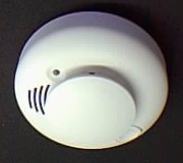
Click to zoom
Application Details
- Equipment Class
- DSS - Part 15 Spread Spectrum Transmitter
- Date of Grant
- May 21, 2000
- Application Purpose
- Original Equipment
- Date of Application
- Mar 26, 2000
- Equipment Note
- transmitter
- Frequency Range
- 906.11000000 - 919.37000000
- Country
- United States
Documents & Files
Document Text
Text extracted from the exhibit documents filed with the FCC. Open a document above to read the original.
Users Manual
© 1999 Inovonics [email protected]: 800.782.2709 www.inovonics.com F202_V1.FM rev 1.10 1/27/00 Page 1 Scope of Manual: This Inovonics manual contains additional installation and servicing information that is not available in the accompanying primary instal- lation manual: ESL 560 Series Wireless Smoke Detector Installation Instructions . This secondary manual is chiefly concerned with transmitter program- ming and servicing the detector in response to trouble indications at the control panel. Typical average standby current...................................................... 38.5μA Typical peak alarm current .............................................................. 91.1mA The FA202 Wireless Smoke Detector, built upon photoelectric Sentrol/ESL technology, continually monitors its own sensitivity and operational status. If it detects a Low Battery condition or is in need of cleaning, it transmits a Low Battery signal that should be interpreted as a “Maintenance Needed” trouble condition at the control panel. If the unit is in need of cleaning, it can be serviced on-site by replacing its Smoke Chamber. Two 3 volt lithium bat- teries, supplied with the product, provide at least one year of operation. T HIS EQUIPMENT SHOULD BE INSTALLED IN ACCORDANCE WITH THE N ATIONAL F IRE P ROTECTION A SSOCIATION ’ S S TANDARD 72. (National Fire Protection Association, Batterymarch Park, Quincy, MA 02269) 1.Locate the transmitter programming pins by disassembling the detector as follows (refer to Figures 4 through 7 in the ESL 560 instructions): a. Remove the red dust cover containing the batteries from the smoke detector. b. With the smoke detector facing you, remove the detector from its Mounting Base by twisting the detector about 15 degrees counter- clockwise with respect to the Mounting Base. c. Remove the Detector Cap by first sliding a flatblade screwdriver part way into the slot on the side of the Detector Cap. Now, gently push the handle down while twisting the Detector Cap counter- clockwise with respect to the Detector Lid. d. Remove the Detector Lid from the Body by pushing down on the Smoke Chamber while pulling up on the bottom of the Lid (see Fig- ure A). e. Remove the Battery Cover that encloses the Battery Compartment by pushing on the area marked OPEN . f.Take the batteries out of the red dust cover holder and load them into the Battery Compartment. Make sure to observe battery polar- ity and that the battery removal ribbon rests under the batteries. g. Refer to Figure B to locate the programming pins on the transmitter board. 2.Using an appropriate Inovonics programming device, set the program- ming options as follows: •External Switch Type: Normally Closed •EOL Resistor: No •Use Internal Contact: No •Check-in Time: 60 seconds Note: These also are the factory default programming options. Some pro- gramming devices like the FA422 Receiver can place an Identification Num- ber into a transmitter without changing the default settings. 3.When prompted by the programming device to plug in the transmitter, connect the programming cable to the 3-pin header. (Orientation of the cable with respect to the 3-pin header is not important; both outside pins on the 3-pin header are at ground potential.) 4.Press the Reset button on the transmitter. When programming is complete, disconnect the cable, test the detector per the Wireless Sensitivity Test Procedure (on the back of this sheet), and reas- semble the smoke detector. FA202 Current Draw Specifications (Supersedes Sentrol ESL 560 specifications) FA202 Wireless Smoke Detector with CleanMe™ Signaling FA202 Wireless Smoke Detector with CleanMe™ Signaling Programming Procedure Figure A: Removing the Detector Lid 3-pin program m ing header Reset button C leanM e disabled position C leanM e enabled position Figure B: Transmitter Board Features FA202 Installation InstallationInstallation Installation Instructions InstructionsInstructions Instructions 900MHz Frequency Agile ® Te c h n o l o g y © 1999 Inovonics [email protected]: 800.782.2709 www.inovonics.com F202_V1.FM rev 1.10 1/27/00 Page 2 If an FA202 fails to operate properly, phone Inovonics Technical Support (800.782.2709) to request a Return Material Authorization (“RMA”) number, then ship the unit to the address shown below. (Please include the RMA number on the package to expedite handling.) Inovonics Corporation Inovonics CorporationInovonics Corporation Inovonics Corporation RMA # ________ RMA # ________RMA # ________ RMA # ________ 2100 Central Ave 2100 Central Ave2100 Central Ave 2100 Central Ave Boulder CO 80301 Boulder CO 80301Boulder CO 80301 Boulder CO 80301 The FA202 should be tested upon initial programming and each time the Smoke Chamber is changed or the batteries are replaced. To make wireless sig- nals from the detector cause an alarm or trouble indication at the control panel, receiver and panel programming must be completed prior to this test. If this has not been done, do so now. To test the detector, follow the procedure described under the Testing the Detector Sensitivity section in the ESL 560 instructions. When the test button is pressed, the LED will flash the number of times that corresponds to its sensitivity. During this test, the control panel should receive an alarm, followed a few seconds later by a restoral. If the panel fails to respond properly, it is possible that the transmitter failed to reset properly when the batteries were installed. To force a trans- mitter reset, remove the batteries from the FA202 for a least 30 seconds, reinstall them, and then retest as described above. As the factory default condition, the FA202 combines the CleanMe signal described in the ESL 560 instructions with its Low Battery signal. If the con- trol panel indicates a Low Battery trouble condition, this should be interpreted as a Maintenance Needed trouble indication. (The battery may be fine, but the detector needs cleaning.) If this multiple-condition pan…
Text truncated - open the document above for the full version.
Attestation Statements
Inovonics Corporation TO:Errol Chang Email:[email protected] FROM:Don Hume DATE:May 15, 2000 SUBJECT:FCC ID: HCQ3B6ESL Correspondence Reference Number: 13776 731 Confirmation Number: EA97168 This is in response to your correspondence to Jeffrey Doolittle at TUV Product Services. TUV performs the majority of the tests and issues the report to us. We (Inovonics Corp.) perform some of the bench-top tests in our lab and complete the submission. Tests are done in-house whever special modifications to the transmitter product are needed to demonstrate compliance with specific requirements. So as to not disturb the radiated characteristics of the test sample used at TUV, a second sample is modified with a micro controller that provides continuous transmissions, sequencing through on all 25 channels in the channel table. The built-in antenna is removed so that a direct coax connection can be soldered in place to make conducted measurements of power and other parameters. The correspondence sent to you on April 27 was a response to your reference number: 13621. It addressed 15.247 (a) (1) and 15.247 (b). I have attached that correspondence in case it was not received. Please give me a call to discuss any firther testing requirements. Don Hume PH: 303-939-9336 ext-112 FAX: 303-939-8977 E-Mail: [email protected]
Attestation Statements
Inovonics Corporation TO:Errol Chang COMPANY:FCC Application Processing Branch FROM:Don Hume DATE:April 27, 2000 SUBJECT:FCC ID: HCQ3B6ESL Correspondence Reference Number: 13621 731 Confirmation Number: EA97168 The following notes to the original submission should help to tie the test data to the relevant rule sections. If there are further questions on this submission, please contact me directly: Don Hume Inovonics Corporation PH: 303-939-9336 E-Mail: [email protected] We will try to use this format to address specific rule sections in future submissions of the FA series transmitters. Additional Notes To FCC ID: HCQ3B6ESL April 26, 2000 The following notes address the requirements of 15.247. 15.247(a)(1) Hopping Sequence and 15.247(g) Occupied Band: The 25 hopping channel sequence is listed in Figure 2 of the Detailed Technical Description. In the table, sequential steps 1 through 25 are tied to channel number. A single packet contains the complete message and the Receiver “captures” the transmitter on any of the 25 channels and performs equally on all channels. Each packet transmitted advances the sequence number one position before the next packet is sent, so that on average, all channels are used equally. The channels are spread at intervals over the occupied band. The occupied Bandwidth and channel spacing plot shows two adjacent channels in the center of the occupied band. Both plots were taken from a test sample specially modified to repeatedly step through the pseudorandom sequence. Because the packet lenght is short, the occupied band plot had to be run for many complete cycles of all 25 channels to get a completed occupied band plot. 15.247(a)(1)(i) Maximum Dwell Time: To minimize clash in this asynchronous one- way system, the delay time between packets is randomized by a function tied to the unique transmitter ID. The standard packet length is 28 mSec as measured in the time domain plot on page C2 of the test report. The average off-time between packets is 120 mSec. A continuously repeating transmission would transmit a maximum of 68 times in a 10 second period or a maximum of three times on any one channel for a maximum occupancy of 3 x 28 mSec or 84 mSec. This is under the limit of 400 mSec in a 10 Sec window. In actual operation, transmissions are much less frequent. 15.247 (b)(2): Conducted Power Measurement: The output power of the transmitter was measured using a direct temporary connection from the antenna port to our laboratory spectrum analyzer. The test samples were modified to allow for continuous re-transmission. The HP-8594E spectrum analyzer was set to 100 kHz IF bandwidth, 20 Mhz span, and 20mSec scan rate. The peak power was measured at +10 dBm at both high and low frequencies. 15.247(c): Out of Band Radiation Limits: These test scans were performed on the test unit specially modified to provide continuously repeating transmissions on three frequencies to allow measurements near the low, center, and high portions of the occupied band. These results are summarized on page A2 of the TUV test report. 15.247(h): Channel Coordination: As a one-way signaling device, each transmitter operates independently and asynchronously, so that the timing and channel position within the sequence are random with respect to any other transmitters operating in the system.
Cover Letter(s)
February 1, 2000 Federal Communications Commission Authorization and Standards Division 7435 Oakland Mills Road Columbia, MD 21046 RE: FCC ID# HCQ3B6ESL Gentlemen: We are submitting our ESL Transmitter for certification. This unit has been tested and complies with FCC Part 15 electromagnetic emission requirements for Unintentional Radiators. If there are any questions regarding this application, please call Inovonics at 303-939-9336. Additionally, $1075.00 will be paid by credit card to cover fees for this application and for Confidential handling of selected portions of the application as required. Thank you for your assistance. Sincerely, Donald J. Hume President DJH/mlb
Cover Letter(s)
February 1, 2000 Mr. Greg Czumak FCC Laboratories Authorization and Standards Division 7435 Oakland Mills Road Columbia, MD 21046 Subject:Request for confidentiality, ESL Transmitter FCC ID: HCQ3B6ESL Dear Mr. Czumak: In the attached files, certain documents contain pages marked CONFIDENTIAL. Please maintain these in the non-public file. Pages marked as CONFIDENTIAL include the “Detailed Technical Description” section and the “Schematic” diagram. This Confidentiality is necessary to protect proprietary information contained within these sections of the application for Certification. Thank you for your help. Sincerely, Donald J. Hume President DJH/mlb
Cover Letter(s)
April 19, 2000 Federal Communications Commission Authorization and Standards Division 7435 Oakland Mills Road Columbia, MD 21046 Attn: Errol Chang RE: FCC ID# HCQ3B6ESL, Confirmation # EA97168, Correspondence #13428 Gentlemen: Originally, test report #B952601a listed the product type of the unit being tested as a transmitter module. However, this was an error in terminology. The ESL transmitter is part of the FA202 product and is not intended to be a module. Therefore, the transmitter was tested in the housing and the FCC label was located on the housing. Subsequently, test report #B952601a has been revised to correctly list the product type as transmitter. The revised test report has been uploaded, along with this letter, using “add attachments” at fcc.gov. If there are further questions or concerns, please contact Donald Hume at 303-939-9336 or at [email protected]. Thank you. Sincerely, Donald J. Hume President DJH/mlb
External Photos
Outside view of ESL with cover in place
External Photos
Outside view of ESL with cover removed
ID Label/Location Info
LABEL SIZE: 1 1/16” X 1 1/16” Label placement Back view of unit FCC label FA-202 INOVONICS CORPORATION BOULDER, COLORADO FCC ID: HCQ3B6ESL This device complies with Part 15 of the FCC Rules: O p e ra tio n is s ub je c t to the fo llo wing two c o nd itio ns : (1 ) This device may not cause harmful interference, and (2) this device must accept any interference receivedd, including interference that may cause undesired operation. Made in USA
Internal Photos
Top view of ESL transmitterTop view of ESL transmitter board with shield removed board with shield in place
Internal Photos
Back view of ESL transmitter board
Operational Description
Inovonics Corporation 2100 Central Ave., Boulder, CO 80301 Customer Service800-782-2709 Main Number303-939-9336 Fax Number303-939-8977 FAX TRANSMISSION ______________________________________________________ This fax consists of __ _ pages (including this cover page). TO:Errol Chang COMPANY:FCC Application Processing Branch FROM:Don Hume DATE:April 27, 2000 SUBJECT:FCC ID: HCQ3B6ESL Correspondence Reference Number :13621 731 Confirmation Number: EA97168 The following notes to the original submission should help to tie the test data to the relevant rule sections. If there are further questions on this submission, please contact me directly: Don Hume Inovonics Corporation PH:303-939-9336 E-Mail: [email protected] We will try to use this format to address specific rule sections in future submissions of the FA series transmitters. Additional Notes To FCC ID: HCQ3B6ESL April 26, 2000 The following notes address the requirements of 15.247. 15.247(a)(1) Hopping Sequence and 15.247(g) Occupied Band: The 25 hopping channel sequence is listed in Figure 2 of the Detailed Technical Description. In the table, sequential steps 1 through 25 are tied to channel number. A single packet contains the complete message and the Receiver “captures” the transmitter on any of the 25 channels and performs equally on all channels. Each packet transmitted advances the sequence number one position before the next packet is sent, so that on average, all channels are used equally. The channels are spread at intervals over the occupied band. The occupied Bandwidth and channel spacing plot shows two adjacent channels in the center of the occupied band. Both plots were taken from a test sample specially modified to repeatedly step through the pseudorandom sequence. Because the packet length is short, the occupied band plot had to be run for many complete cycles of all 25 channels to get a completed occupied band plot. 15.247(a)(1)(i) Maximum Dwell Time: To minimize clash in this asynchronous one- way system, the delay time between packets is randomized by a function tied to the unique transmitter ID. The standard packet length is 28 mSec as measured in the time domain plot on page C2 of the test report. The average off-time between packets is 120 mSec. A continuously repeating transmission would transmit a maximum of 68 times in a 10 second period or a maximum of three times on any one channel for a maximum occupancy of 3 x 28 mSec or 84 mSec. This is under the limit of 400 mSec in a 10 Sec window. In actual operation, transmissions are much less frequent. 15.247 (b)(2): Conducted Power Measurement: The output power of the transmitter was measured using a direct temporary connection from the antenna port to our laboratory spectrum analyzer. The test samples were modified to allow for continuous re-transmission. The HP-8594E spectrum analyzer was set to 100 kHz IF bandwidth, 20 MHz span, and 20mSec scan rate. The peak power was measured at +10 dBm at both high and low frequencies. 15.247(c): Out Of Band Radiation Limits: These test scans were performed on the test unit specially modified to provide continuously repeating transmissions on three frequencies to allow measurements near the low, center, and high portions of the occupied band. These results are summarized on page A2 of the TUV test report. 15.247(h): Channel Coordination: As a one-way signaling device, each transmitter operates independently and asynchronously, so that the timing and channel position within the sequence are random with respect to any other transmitters operating in the system.
Test Report
FCC ID: HCQ3B6ESLTEST REPORT: B952601 ADDENDUM TO TEST REPORT B952601a Occupied Bandwidth: 320 kHz Second Plot
Test Report
FCC ID: HCQ3B6ESL File No. BC1G952601, Page 1 of 7 TÜV PRODUCT SERVICE INC40 Meadow RoadPinewood Springs, Lyons, CO 80540Tel: 303 786 7999Fax: 303 449 3004Rev.No 1.0 EMC EMISSION - TEST REPORT Test Report No. B952601a Issue Date 23 March, 2000 Model / Serial No.FA-202 / 1 Product TypeTransmitter Module Client Inovonics Corporation Manufacturer Inovonics Corporation License holder Inovonics Corporation Address 2100 Central Avenue Boulder, CO 80301 Test Criteria AppliedFCC Part 1515.247C Test Start Date: 23 December,1999 Test End Date: 23 December,1999 Test Result nn PASSoo FAIL Test Report Project No. BC1G952601 Total Pages including Appendices 32 Reviewed By : Shawn SinghReviewed By : Jeffrey V. Doolittle TÜV Product Service Inc is a subcontractor to TÜV Product Service, GmbH according to the principles outlined in ISO/IEC Guide 25 and EN 45001. TÜV Product Service Inc reports apply only to the specific samples tested under stated test conditions. It is the manufacturer's responsibility to assure that additional production units of this model are manufactured with identical electrical and mechanical components. TÜV Product Service Inc shall have no liability for any deductions, inferences or generalizations drawn by the client or others from TÜV Product Service Inc issued reports. This report is the confidential property of the client. As a mutual protection to our clients, the public and ourselves, extracts from the test report shall not be reproduced except in full without our written approval of TÜV Product Service. This report shall not be used by the client to claim product endorsement by NVLAP or any agency of the US government. TÜV Product Service Inc and its professional staff hold government and professional organization certifications and are members of AAMI, ACIL, AEA, ANSI, IEEE, NVLAP, and VCCI PRODUCT SERVICE FCC ID: HCQ3B6ESL File No. BC1G952601, Page 2 of 7 TÜV PRODUCT SERVICE INC40 Meadow RoadPinewood Springs, Lyons, CO 80540Tel: 303 786 7999Fax: 303 449 3004Rev.No 1.0 DIRECTORY - EMISSIONS Page(s) Documentation Test report1 - 3 Directory2 Test Regulations3 General Remarks3 Test-setup Photographs4 - 5 Test Equipment Used6 - 7 Appendix A Transmitter Data Sheets A1 – A2 Appendix B Detailed Test Data Sheets B1 – B9 Appendix C Time Domain Plots of Single Data Packet C1 – C2 Appendix D Test Plan/Constructional Data Form D1 – D9 Appendix E Measurement of Protocol E1 – E3 PRODUCT SERVICE FCC ID: HCQ3B6ESL File No. BC1G952601, Page 3 of 7 TÜV PRODUCT SERVICE INC40 Meadow RoadPinewood Springs, Lyons, CO 80540Tel: 303 786 7999Fax: 303 449 3004Rev.No 1.0 EMISSIONS TEST REGULATIONS : The tests were performed according to following regulations : n - Federal Communication Commission part 15o - Class An - Class B n - Federal Communication Commission part 15, Subpart Cn - 15.209n - 15.247 -------------------------------------------------------------------------------- All tests performed according to ANSI C63.4. Emission Test Results: Conducted emissions 450 kHz - 30 MHz Test Resultoo - PASS oo - FAILnn - Not Applicable Passing MargindBatMHz Remarks:EUT is battery operated. Radiated emissions (electric field) 30 MHz - 1000 MHz (Unintentional Radiator) Test Resultnn - PASS oo - FAILoo - Not Applicable Passing Margin25.9dBat35MHz Remarks: Radiated emissions (electric field) 906.11 MHz - 9193.7 MHz (Intentional Radiator) Test Resultnn - PASS oo - FAILoo - Not Applicable Passing Margin6.1dBat4530.7MHz Remarks: GENERAL REMARKS: Modifications required to pass: None Test Specification Deviations: Additions to or Exclusions from: None PRODUCT SERVICE FCC ID: HCQ3B6ESL File No. BC1G952601, Page 4 of 7 TÜV PRODUCT SERVICE INC40 Meadow RoadPinewood Springs, Lyons, CO 80540Tel: 303 786 7999Fax: 303 449 3004Rev.No 1.0 Test-setup photo(s) Radiated Emissions PRODUCT SERVICE FCC ID: HCQ3B6ESL File No. BC1G952601, Page 5 of 7 TÜV PRODUCT SERVICE INC40 Meadow RoadPinewood Springs, Lyons, CO 80540Tel: 303 786 7999Fax: 303 449 3004Rev.No 1.0 Test-setup photo(s): Conducted Emissions Test Not Applicable PRODUCT SERVICE FCC ID: HCQ3B6ESL File No. BC1G952601, Page 6 of 7 TÜV PRODUCT SERVICE INC40 Meadow RoadPinewood Springs, Lyons, CO 80540Tel: 303 786 7999Fax: 303 449 3004Rev.No 1.0 Test Equipment Used PRODUCT SERVICE FCC ID: HCQ3B6ESL File No. BC1G952601, Page 7 of 7 TÜV PRODUCT SERVICE INC40 Meadow RoadPinewood Springs, Lyons, CO 80540Tel: 303 786 7999Fax: 303 449 3004Rev.No 1.0 Equipment ReportEquipment Report 23-Dec-1999 Project Number:Project Number:B9526Project Date:23-Dec-1999 Company Name:Company Name:Inovonics Corporation Equip ModelSerialCalibrationCal IDManufacturerNumberNumberDescriptionDateIntervalDueCode Test PerformedRRadiated Emissions 2679HEWLETT-PACKARD85650A2430A00550Quasi Peak Adapter07-Jun-19991206-Jun-2000G 7514A.H.SYSTEMSSAS-200/512104Log Periodic Antenna28-Jul-19991227-Jul-2000G (200-1500 MHz) 8179EMCO31082149Biconical Dipole 28-Jun-19991227-Jun-2000G Antenna (30-300 MHz) 8207AVANTEKAWT-180371002RF Pre-Amplifier 02-Dec-19991201-Dec-2000G (8-18 GHz) 8208AVANTEKAFT-8434-10F1007RF Pre-Amplifier 02-Dec-19991201-Dec-2000G (4-8 GHz) 8212MINI CIRCUITSZHL-1042J-SMAD020499-5RF 12-Feb-19991212-Feb-2000Y Pre-Amplifier(.01-4. 2 GHz) 8213HEWLETT PACKARD8566B2410A00154Spectrum Analyzer 15-Apr-19991214-Apr-2000G (dc-22 GHz) 8214HEWLETT PACKARD85662A2403A08749Display Section15-Apr-19991214-Apr-2000G 8219HEWLETT PACKARD8445B2034A03223Pre-Selector24-Jun-19991223-Jun-2000G 8264EMCO31159205-38866Horn Antenna05-Apr-19991204-Apr-2000G Cal Code Legend: G=Out Source, Y=No Cal required, R=Out of Service, B=In-House Verification Required FCC ID: HCQ3B6ESL File No. BC1G952601, Page A1 of A2 TÜV PRODUCT SERVICE INC40 Meadow RoadPinewood Springs, Lyons, CO 80540Tel: 303 786 7999Fax: 303 449 3004Rev.No 1.0 Appendix A Transmitter Data Sheets PRODUCT SERVICE FCC ID: HCQ3B6ESL File No. BC1G952601, Page A2 of A2 TÜV PRODUCT SERVICE INC40 Meadow RoadPinewood Springs, Lyons, CO 80540Tel: 303 786 7999Fax: 303 449 3004Rev.…
Text truncated - open the document above for the full version.
Test Report
FCC ID: HCQ3B6ESL File No. BC1G952601, Page 1 of 7 TÜV PRODUCT SERVICE INC40 Meadow RoadPinewood Springs, Lyons, CO 80540Tel: 303 786 7999Fax: 303 449 3004Rev.No 1.0 EMC EMISSION - TEST REPORT Test Report No. B952601b Issue Date21 April, 2000 Model / Serial No.FA-202 / 1 Product TypeTransmitter Client Inovonics Corporation Manufacturer Inovonics Corporation License holder Inovonics Corporation Address 2100 Central Avenue Boulder, CO 80301 Test Criteria AppliedFCC Part 1515.247C Test Start Date: 23 December,1999 Test End Date: 23 December,1999 Test Result nn PASSoo FAIL Test Report Project No. BC1G952601 Total Pages including Appendices34 Reviewed By : Shawn SinghReviewed By : Jeffrey V. Doolittle TÜV Product Service Inc is a subcontractor to TÜV Product Service, GmbH according to the principles outlined in ISO/IEC Guide 25 and EN 45001. TÜV Product Service Inc reports apply only to the specific samples tested under stated test conditions. It is the manufacturer's responsibility to assure that additional production units of this model are manufactured with identical electrical and mechanical components. TÜV Product Service Inc shall have no liability for any deductions, inferences or generalizations drawn by the client or others from TÜV Product Service Inc issued reports. This report is the confidential property of the client. As a mutual protection to our clients, the public and ourselves, extracts from the test report shall not be reproduced except in full without our written approval of TÜV Product Service. This report shall not be used by the client to claim product endorsement by NVLAP or any agency of the US government. TÜV Product Service Inc and its professional staff hold government and professional organization certifications and are members of AAMI, ACIL, AEA, ANSI, IEEE, NVLAP, and VCCI PRODUCT SERVICE FCC ID: HCQ3B6ESL File No. BC1G952601, Page 2 of 7 TÜV PRODUCT SERVICE INC40 Meadow RoadPinewood Springs, Lyons, CO 80540Tel: 303 786 7999Fax: 303 449 3004Rev.No 1.0 DIRECTORY - EMISSIONS Page(s) Documentation Test report1 - 3 Directory2 Test Regulations3 General Remarks3 Test-setup Photographs4 - 5 Test Equipment Used6 - 7 Appendix A Transmitter Data Sheets A1 – A2 Appendix B Detailed Test Data Sheets B1 – B9 Appendix C Time Domain Plots of Single Data Packet C1 – C2 Appendix D Test Plan/Constructional Data Form D1 – D9 Appendix E Measurement of Protocol E1 – E3 PRODUCT SERVICE FCC ID: HCQ3B6ESL File No. BC1G952601, Page 3 of 7 TÜV PRODUCT SERVICE INC40 Meadow RoadPinewood Springs, Lyons, CO 80540Tel: 303 786 7999Fax: 303 449 3004Rev.No 1.0 EMISSIONS TEST REGULATIONS : The tests were performed according to following regulations : n - Federal Communication Commission part 15 o - Class An - Class B n - Federal Communication Commission part 15, Subpart Cn - 15.209n - 15.247 -------------------------------------------------------------------------------- All tests performed according to ANSI C63.4. Emission Test Results: Conducted emissions 450 kHz - 30 MHz Test Resultoo - PASS oo - FAILnn - Not Applicable Passing MargindBatMHz Remarks:EUT is battery operated. Radiated emissions (electric field) 30 MHz - 1000 MHz (Unintentional Radiator) Test Resultnn - PASS oo - FAILoo - Not Applicable Passing Margin25.9dBat35MHz Remarks: Radiated emissions (electric field) 906.11 MHz - 9193.7 MHz (Intentional Radiator) Test Resultnn - PASS oo - FAILoo - Not Applicable Passing Margin6.1dBat4530.7MHz Remarks: GENERAL REMARKS: Per Customer, the equipment tested was a Transmitter not a Transmitter Module as reflected in the Constructional Data Form. Modifications required to pass: None Test Specification Deviations: Additions to or Exclusions from: None PRODUCT SERVICE FCC ID: HCQ3B6ESL File No. BC1G952601, Page 4 of 7 TÜV PRODUCT SERVICE INC40 Meadow RoadPinewood Springs, Lyons, CO 80540Tel: 303 786 7999Fax: 303 449 3004Rev.No 1.0 Test-setup photo(s) Radiated Emissions PRODUCT SERVICE FCC ID: HCQ3B6ESL File No. BC1G952601, Page 5 of 7 TÜV PRODUCT SERVICE INC40 Meadow RoadPinewood Springs, Lyons, CO 80540Tel: 303 786 7999Fax: 303 449 3004Rev.No 1.0 Test-setup photo(s): Conducted Emissions Test Not Applicable PRODUCT SERVICE FCC ID: HCQ3B6ESL File No. BC1G952601, Page 6 of 7 TÜV PRODUCT SERVICE INC40 Meadow RoadPinewood Springs, Lyons, CO 80540Tel: 303 786 7999Fax: 303 449 3004Rev.No 1.0 Test Equipment Used PRODUCT SERVICE FCC ID: HCQ3B6ESL File No. BC1G952601, Page 7 of 7 TÜV PRODUCT SERVICE INC40 Meadow RoadPinewood Springs, Lyons, CO 80540Tel: 303 786 7999Fax: 303 449 3004Rev.No 1.0 Equipment ReportEquipment Report 23-Dec-1999 Project Number:Project Number:B9526Project Date:23-Dec-1999 Company Name:Company Name:Inovonics Corporation Equip ModelSerialCalibrationCal IDManufacturerNumberNumberDescriptionDateIntervalDueCode Test PerformedRRadiated Emissions 2679HEWLETT-PACKARD85650A2430A00550Quasi Peak Adapter07-Jun-19991206-Jun-2000G 7514A.H.SYSTEMSSAS-200/512104Log Periodic Antenna28-Jul-19991227-Jul-2000G (200-1500 MHz) 8179EMCO31082149Biconical Dipole 28-Jun-19991227-Jun-2000G Antenna (30-300 MHz) 8207AVANTEKAWT-180371002RF Pre-Amplifier 02-Dec-19991201-Dec-2000G (8-18 GHz) 8208AVANTEKAFT-8434-10F1007RF Pre-Amplifier 02-Dec-19991201-Dec-2000G (4-8 GHz) 8212MINI CIRCUITSZHL-1042J-SMAD020499-5RF 12-Feb-19991212-Feb-2000Y Pre-Amplifier(.01-4. 2 GHz) 8213HEWLETT PACKARD8566B2410A00154Spectrum Analyzer 15-Apr-19991214-Apr-2000G (dc-22 GHz) 8214HEWLETT PACKARD85662A2403A08749Display Section15-Apr-19991214-Apr-2000G 8219HEWLETT PACKARD8445B2034A03223Pre-Selector24-Jun-19991223-Jun-2000G 8264EMCO31159205-38866Horn Antenna05-Apr-19991204-Apr-2000G Cal Code Legend: G=Out Source, Y=No Cal required, R=Out of Service, B=In-House Verification Required FCC ID: HCQ3B6ESL File No. BC1G952601, Page A1 of A2 TÜV PRODUCT SERVICE INC40 Meadow RoadPinewood Springs, Lyons, CO 80540Tel: 303 786 7999Fax: 303 449 3004Rev.No 1.0 Appendix A Transmitter Data Sheets PRODUCT SERVICE FCC ID: HCQ3B6ESL File No. BC1G952601, Page A…
Text truncated - open the document above for the full version.
Test Report
REVISION A, 4/27/00 FCC ID: HCQ3B6ESLTEST REPORT: B952601a ADDENDUM, REVISION A, TO TEST REPORT B952601a Occupied Bandwidth: 320 kHz Second Plot: Occupied Band, All 25 Channels
Test Report
REVISION B, 5/16/00 FCC ID: HCQ3B6ESLTEST REPORT: B952601b ADDENDUM, REVISION B, TO TEST REPORT B952601b Occupied Bandwidth: 320 kHz Second Plot: Occupied Band, All 25 Channels
Contact Information
Applicant
Jess Cobb(Manager of Program Mgmt)
Test Firm
International Approval Laboratories, LLCTodd Seeley
Technical Specifications
| # | Rule Parts | Frequency Range | Power Output |
|---|---|---|---|
| 1 | 15C | 906.11 MHz - 919.37 MHz | 10.00 mW |
Other Applications from Inovonics Wireless Corporation

HCQ-IDTOUCH1
May 13, 2026Inovonics Wired Touchscreen Keypad
Equipment Class
DTS - Digital Transmission System
HCQBWA02
Aug 28, 2024Flush Mount Locator
Equipment Class
DSS - Part 15 Spread Spectrum Transmitter
HCQTBA
Sep 21, 2022TBA Module
Equipment Class
DSS - Part 15 Spread Spectrum Transmitter
HCQPFA01
Jul 14, 2022Fall Detect Transmitter
Equipment Class
DSS - Part 15 Spread Spectrum Transmitter
HCQ3B6BRGSA
Sep 22, 2020Bluetooth to EchoStream Bridge
Equipment Class
DTS - Digital Transmission System