HCQ3B6ETICR65PIR Transmitter
Inovonics Wireless Corporation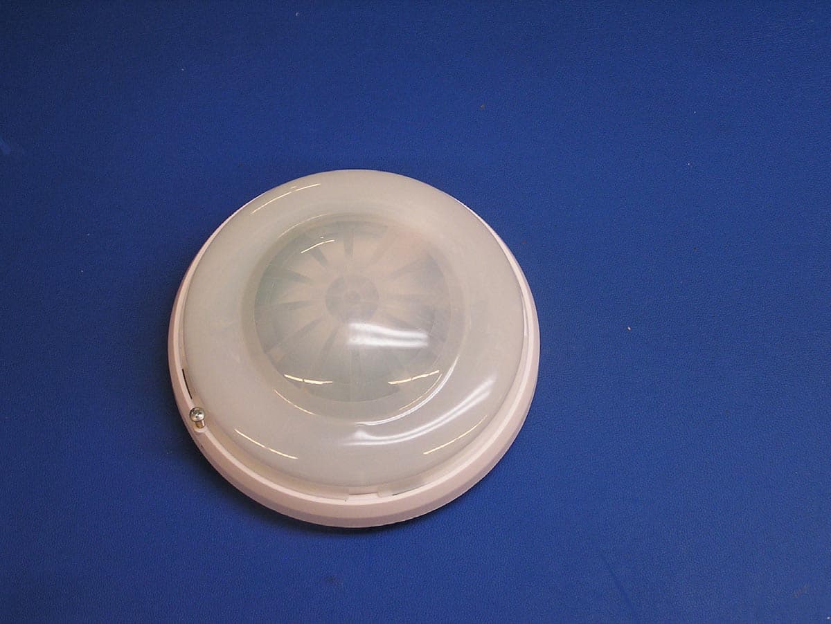
Click to zoom
Application Details
- Equipment Class
- DSS - Part 15 Spread Spectrum Transmitter
- Date of Grant
- Nov 04, 2004
- Application Purpose
- Original Equipment
- Date of Application
- Sep 14, 2004
- Equipment Note
- PIR Transmitter
- Frequency Range
- 902.00000000 - 928.00000000
- Country
- United States
Documents & Files
Document Text
Text extracted from the exhibit documents filed with the FCC. Open a document above to read the original.
Users Manual
EchoStream™ Select ES1265 336600°° PPaassssiivvee IInnffrraaRReedd MMoottiioonn DDeetteeccttoorr Installation and Operation Manual - 04098A IMPORTANT NOTES •Products, unless specifically noted, are intended for indoor use. •Manually test all products regularly. •These products are designed to be installed and maintained by pro- fessional security technicians. OVERVIEW: The ES1265 is a wireless, ceiling-mounted 4-element passive infrared intrusion detector providing protection from intruders by pyro-sensor array. Micro-con- troller PIR signal analysis with special ASIC technology for PIR pulse processing increases immunity to RFI, vibration, static, lightning, ambient temperature changes and other common causes of false alarms. LOCATING THE DETECTOR: Choose a location most likely to intercept an intruder. Refer to the following recommendations: •Temperature changes: Do not install the detector outdoors or in a place exposed to sudden temperature changes, or near equipment such as air conditioners, ventilators, fans, heaters, etc. •Bright light: Avoid bright light, direct or reflected sunlight, automobile headlights or other light sources. •Moving Objects: Objects that may move or vibrate, such as curtains, window blinds or decorative banners can cause false alarms. •Exposure to contaminants: Airborne vapors, mists, steam, or fumes can cause detector malfunction. •Curtains, Glass, Screens: Infrared energy cannot pass through opaque objects or through transparent or semi-trans- parent materials such as glass, paper, or curtains. Barriers of these materials create "blind-spots" in intrusion protec- tion. •Detection Zones: Refer to zone pattern diagrams to determine optimal mounting locations. MOUNTING THE DETECTOR: 1. Remove cover from the detector body by loosening the lock screw about 5mm and turning the cover counterclock- wise. (See Figure 3.) 2. Remove the body from the bracket by turning it counterclockwise. 3. Mount the bracket to the ceiling. Hold the bracket on the ceiling. Mark and drill 4 holes for installation. 4. Attach the detector body. Install the battery and place the detector body so that the arrow is aligned with the dot on the bracket. Turn clockwise until the arrow on the body aligns with the arrow on the bracket. (See Figure 3.) 5. Set Pulse Sensitivity jumper in desired position. Set Frequency Band Selector. (See Figure 1.) 6. Register the transmitter as described below. 7. Attach the cover. Place the four tabs of the cover into the matching notches in the base and turn the cover clock- wise until it fits tightly. MOUNTING HEIGHT The ES1265 can be mounted to a maximum height of approximately 18 feet (5.5 meters). At 18', the PIR detection pattern is about twice the diameter of a 10' (3m) installation. As mounting height increases, distance between detection zones also increases toward the perimeter, and the effects of factors such as floor surface temperature and intruder direction and speed are intensified. This can contribute to reducing speed of detection. (See Figures 4-6.) Every installation should include a Walk Test of detection zones, including intrusion paths crossing the edges of the zones. PIR SENSITIVITY The Pulse Count jumper setting provides control for normal or difficult operating environments. Automatic Pulse Count is recommended for reliable operation in environments which may be subject to temperature fluctuations that might cause false alarms. The Single Pulse Count mode is more sensitive to minor temperature variations, and should be used in sites where variant heat sources will not cause alarms (See Figure 1.) REGISTERING Transmitters must be registered with the system receiver in order to be monitored and supervised. Each transmitter has a unique factory-programmed identification number. Refer to the receiver installation instructions for details on registering a transmitter. 1. Remove the ES1265 cover as described in “Mounting the Detector.” 2. To register a transmitter: when prompted by the receiver to "Reset Transmitter", press the Reset button. (See Figure 1.) Replace the ES1265 cover. Follow instructions to test the transmitter. Note: TThe EES1265 rretains pprogramming ddata iin nnon-vvolatile mmemor y. It does not require re-programming after loss of power. Install a new battery and press the reset button to re-initialize the transmitter and restore programming. , ABattery BTamper Switch CReset Button DPIR Sensitivity ETest LED FWalk Test button GWalk Test Reed Switch HFrequency Band Selector Figure 1 PIR HeightDiameter 8'(2.4m)31' (9.3m) 10'(3m)38' (11.7m) 12'(3.6m)46' (9.34m) 18'(5.5m)70' (21m) Figure 5Figure 4Figure 6 Figure 2 Figure 3 Approximate Effective Detection Diameter* * See "Mounting Height" AU (915-928MHz) EU (868-869 MHz) NZ (921-928MHz US (902-928MHz) MF4232 compatible (915-928MHz) WALK TEST: With the cover on the unit, quickly (less than ½ second) pass a magnet near the Walk Test Reed Switch (Figure 1-G). This activates a 1-minute walk test mode. Within this period, the Test LED will light every time the PIR senses motion. The unit will not transmit alarm signals during this test period. Note: The LED indicator lights only during 1-minute walk test period, and during transmission test. TRANSMISSION TEST: With the cover on the unit, hold a magnet near the Walk Test Reed Switch for at least 1 second. This activates a 1-minute transmission test mode. Within this period, the unit will transmit alarm and restoral cycles at regular intervals for approximately one minute. The LED will light every time the unit transmits. OPERATION: The ES1265 transmitter signals an alarm condition when motion is detected by the sensor. Once an alarm condition is signaled, further alarms are suppressed until no motion is sensed for a period of more than 90 seconds. TECHNICAL SPECIFICATIONS: Dimensions:5.2" x 2.25" (131mm x 57mm) Weight:6.52 oz. (185g) Detection Method:4-element PIR Operating Temperature:32°F to 120°F (0°C to 49°C) Humidity:10% to 90…
Text truncated - open the document above for the full version.
Cover Letter(s)
September 1, 2004 Federal Communications Commission Authorization and Standards Division 7435 Oakland Mills Road Columbia, MD 21046 Subject: Request for Confidentiality for FCC ID# HCQ3B6ETICR65 Gentlemen: The following reports are marked confidential, and should be maintained in the non- public file. This confidentiality is necessary to protect proprietary information contained within these sections of the application for Certification. 1) Operational Description 2) Schematics 3) Block Diagram Thanks for your help. Sincerely, Donald J. Hume President
External Photos
FCC ID: HCQ3B6ETICR65 ES1265 4. External Photos: Topside view. Bottom side view FCC Label
ID Label/Location Info
FCC ID HCQ3B6ETICR65 IC: 2309A-ETICR65 This device complies with Part 15 of the FCC rules. Operation is subject to the following two conditions: (1) This device may not cause harmful interference, and (2) this device must accept any interfer- ence received, including interference that may cause undesired operation . ES1265 Louisville, CO - www.inovonics.com CONFIDENTIAL DOCUMENT LBL-CE-ES1265 04057B CONFIDENTIAL DOCUMENTATION The information contained in this document is confidential to and the sole property of Inovonics Corporation. Receipt of this information requires the existence and full acceptance of the terms and conditions of a Non Disclosure Agreement signed by the Inovonics Corporation and the Recipient. This documentation is not to be reproduced or redistributed except as provided in the Non Disclosure Agreement. MATERIAL:.002" THICK CLEAR MYLAR WITH .001" GLOSSY LAMINATION (FOR PROTEC- TION FROM INK SMEARING) AND PERMANENT ADHESIVE APPLIED TO THE BACKSIDE ARTWORK:SUPPLIED BY INOVONICS TEXT: BLACK LABEL SIZE: 1.062" X .1.062" (SHOWN TO 3 TIMES SCALE) WITH .125 RADIUS ON EACH COR- NER AND NO BORDER PACKAGING AND LABEL ORIENTATION:LABELS TO BE SUPPLIED ON TOP SIDE OF ROLL STOCK WITH TEXT READABLE AS VIEWED FROM BOTTOM (SHORT) EDGE OF ROLL Rev. Level DescriptionDate AInitial Release5/18/04 BChange FCC and IC numbers6/22/04 Confidential to InovonicsES1265Rev B FCC ID HCQ3B6ETICR65 IC: 2309A-ETICR65 This device complies with Part 15 of the FCC rules. Operation is subject to the following two conditions: (1) This device may not cause harmful interference, and (2) this device must accept any interference received, including interference that may cause undesired operation . ES1265 Louisville, CO - www.inovonics.com
Internal Photos
FCC ID: HCQ3B6ETICR65 ES1265 6. Internal photos: Cover Removed PCB topside PCB bottomside Integrated Antenna RF Shielding
Test Report
EMC EMISSIONS - TEST REPORT (In-Part) Test Report No. BC400278f-1 Issue Date: July 12, 2004 Model / Serial No. ES1265 / proto #1 Product Type Intentional Transmitter Client Inovonics Wireless Corp. Manufacturer Inovonics Wireless Corp. License holder Inovonics Wireless Corp. 315 CTC Blvd Address Louisville, CO 80027 Test Criteria Applied FCC CFR47 Part 15.247 Test Result PASS Test Project Number References BC400278-1 Total Pages Including Appendices: 34 Title 47 CFR 15: RADIO FREQUENCY DEVICES Reviewed By : Approved By : INTERNATIONAL APPROVALS LABORATORIES (IAL) reports apply only to the specific samples tested under stated test conditions. It is the manufacturer's responsibility to assure that additional production units of this model are manufactured with identical electrical and mechanical components. IAL have no liability for any deductions, inferences or generalizations drawn by the client or others from IAL issued reports. This report is the confidential property of the client. As a mutual protection to our clients, the public and ourselves, extracts from the test report shall not be reproduced except in full without our written approval of IAL. This report shall not be used by the client to claim product endorsement by NVLAP (No. 200624- 0) or any agency of the US government. International Approval Laboratories and its professional staff hold government and professional organization certifications and are members of IEEE, NVLAP, and VCCI. Project File: BC400278 Page 2 of 34 International Approvals Laboratories, LLC 5541 Central Avenue, Suite 110 Boulder, Colorado 80301 Voice: 303 786 7999 Fax: 303 449 6160 Rev.No 1 D I R E C T O R Y Documentation Page(s) Test report 1 - 34 Directory 2 Test Regulations 3 General Remarks 4-5 Test-setup Photographs 6-10 Appendix A Test Data Sheets and Test Equipment Used 11-26 Appendix B Test Plan/Constructional Data Form 27-29 Appendix C Measurement Protocol/Test Procedures 30-34 STATEMENT OF MEASUREMENT UNCERTAINTY The data and results referenced in this document are true and accurate. The measurement uncertainty for Conducted Emissions in the frequency range of 150kHz – 30MHz is calculated to be ±2.30dB and for Radiated Emissions is calculated to be ±3.60dB in the frequency range of 30MHz – 200MHz and ±3.38dB in the frequency range of 200MHz – 1000MHz. EUT Received Date: 1-June-2004 Testing Start Date: 1-June-2004 Testing End Date: 6-July-2004 Project File: BC400278 Page 3 of 34 International Approvals Laboratories, LLC 5541 Central Avenue, Suite 110 Boulder, Colorado 80301 Voice: 303 786 7999 Fax: 303 449 6160 Rev.No 1 The tests were performed according to following regulations : 1. FCC CFR47 Part 15.205 2. FCC CFR47 Part 15.207 3. FCC CFR47 Part 15.209 4. FCC CFR47 Part 15.247 5. ICES-003 Emission Test Results: Conducted Emissions, Powerline (15.207) - Not Applicable Test Result Minimum limit margin NA dB at NA MHz Maximum limit exceeding dB at MHz Remarks: Battery operated device. Radiated Emissions (15.209) - PASS Test Result Minimum limit margin -13.5 dB at 204.18 MHz Maximum limit exceeding dB at MHz Remarks: Radiated Emissions (15.205)/(15.247)(c) - PASS Test Result Minimum limit margin -7.68 dB at 2744.11 MHz Maximum limit exceeding dB at MHz Remarks: Peak Output Power (15.247) (b)(1) - PASS Test Result Minimum limit margin -25.18 dB at 902.19 MHz Maximum limit exceeding dB at MHz Remarks: Project File: BC400278 Page 4 of 34 International Approvals Laboratories, LLC 5541 Central Avenue, Suite 110 Boulder, Colorado 80301 Voice: 303 786 7999 Fax: 303 449 6160 Rev.No 1 GENERAL REMARKS: The following remarks are to be considered as “where applicable“ and are taken into account while completing any FCC/IC/ETSI radio tests at International Approvals Laboratories, LLC. Testing was performed in 3 different orthogonal axis to determine the worst case emissions from the device. The worst case emissions measurements are shown in this report. FCC CFR47 Part 15.31: Measurement Standards: In any case where the device is powered off a battery, a fresh battery was used during test. In cases where the device is powered off an AC supply, voltage was varied per Part 15.31 to find worst case emissions. FCC CFR47 Part 15.35: Measurement Detector Functions and Bandwidths: FCC Part 15.35 was utilized when performing the measurements within this report. In any case where the device is powered off a battery, a fresh battery was used during test. In cases where the device is powered off an AC supply, voltage was verified per Part 15.31 to find worst case emissions. The actual test distance for the FCC Part 15.209 testing was conducted at 10m for the fact that the device was being tested to EN55022 Class B from 30 MHz to 1000 MHz (meets/exceeds the FCC Part 15.209 & 109B limits) The data is automatically extrapolated back to the FCC 3m limits and measurements are corrected to better show the compliance to FCC requirements and reduce confusion. A correction factor of 10.54dB is used in cases of 30MHz and up for a difference between 10m and 3m measurement distances. All measurements that are lesser than 30MHz where applicable are accompanied with the fall of measurements and calculations to support the interpolation. Modifications required to pass: Test Specification Deviations: Additions to or Exclusions from This test report is in-part, International Approvals Laboratories, LLC was asked to test only the field strength of the fundamental and harmonics as well as the unintentional radiated and conducted emissions when applicable. Project File: BC400278 Page 5 of 34 International Approvals Laboratories, LLC 5541 Central Avenue, Suite 110 Boulder, Colorado 80301 Voice: 303 786 7999 Fax: 303 449 6160 Rev.No 1 Required Information In Accordance to FCC CFR 47 Part 2.1033: Exhibits Including (where applicable): 1. Users Manual 2. Operation Description 3. Block Diagram 4. Report of Measurement 5. External & Internal Photographs 6. Schematic 7. Parts List 8. Tuning Procedur…
Text truncated - open the document above for the full version.
Test Report
FCC ID: HCQ3B6ETICR65 ES1265 11. Test Report The test report containing intentional/unintentional emissions data is attached as “BC400278f-1 ES1265.pdf”. International Approvals Laboratories generated this report. Additional data demonstrating compliance with 47CFR15.247 follows. For the following measurements, the antenna was replaced by a coaxial connection to an HP8594E spectrum analyzer. Minimum Channel Separation: Plot 1 is a spectrum plot showing a minimum channel separation of 800 kHz. Compliance with section 15.247(a)(1) is demonstrated by capturing several transmissions over a small portion of the 902-928 MHz ISM band. Plot 1: Demonstration of channel spacing requirement. Number of hopping Channels: Plot 2 demonstrates compliance with 15.247(a)(1)(i) — Number of hopping channels. This is a stored display of many sequential transmissions to show the overall band occupied by the transmitter. The marker at 919.20 MHz represents the maximum conducted transmitter power across the band. Plot 2: Demonstration of 25 hopping channels. 20 dB bandwidth of a single channel: Plot 3 shows the 20 dB bandwidth of a single channel to demonstrate compliance with 15.247(a)(1)(i). The 20 dB occupied bandwidth is 253.8 kHz. Plot 3: Demonstration of occupied bandwidth. Average radiated measurements for harmonic and spurious emissions: With regards to average radiated measurements for harmonic and spurious emissions that fall in the restricted bands of section 15.205 of the FCC Rules. This device uses pulsed operation, section 15.35(c) states, “Unless otherwise specified, e.g.§ 15.255(b), when the radiated emission limits are expressed in terms of the average value of the emission, and pulsed operation is employed, the measurement field strength shall be determined by averaging over one complete pulse train, including blanking intervals, as long as the pulse train does not exceed 0.1 seconds.” This device transmits for 20ms out of every 100ms and therefore has a duty cycle of 20%. Per section 15.35 the peak harmonic and spurious emissions may exceed the General Radiation Limit found in 15.209(a) by the ratio of the duty cycle, which in this case results in a 14 dB relaxation of the limit from 54 dB μV/m to 68 dB μV/m (above 1000 MHz) for the peak measurements shown in the report. Peak conducted RF power output measurements: Pursuant to FCC Public Notice DA 00-705, the following measurements were made using an Agilent 8594E spectrum analyzer having the following settings: Span: 1250 kHz (approximately 5 times the 20dB bandwidth) RBW: 300 kHz (RBW > the 20dB bandwidth) VBW: 300 kHz (VWB ≥ RBW) Sweep: auto Detector: peak Trace: max hold The device is modified so that the antenna is removed and a 3” semi-rigid coaxial cable having negligible insertion loss connects it to the spectrum analyzer. Please note that the device is designed to have an output power of +17dBm however a variation of +1, -2dB is anticipated. Plot 4: RF output at the low channel Plot 5: RF output at the middle channel Plot 6: RF output at the high channel Conducted spurious and harmonic emissions measurements: There is no way to measure conducted spurious and harmonic emissions without altering the device. The device was taken to an accredited and listed lab, International Approvals Laboratories, and the relevant radiated measurements were taken using their 3-meter Open-Air Test Site. Average time of occupancy measurement: Section 15.247(a)(1)(i) stated, “...if the 20 dB bandwidth of the hopping channel is 250kHz or greater, the system shall use at least 25 hopping frequencies and the average time of occupancy on any frequency shall not be greater than 0.4 seconds within a 10 second period” To effectively obtain this measurement, FCC Public Notice DA 00-705 requires the following spectrum analyzer settings: Span: 0 RBW: 1MHz VBW: 1MHz (VBW ≥ RBW) Sweep: 60ms (as necessary to capture the entire dwell time per hopping channel) Detector: peak Trace: max hold Plot 6 below clearly shows the dwell time is less than the 0.4 seconds required by 15.247(a)(1)(i).
Test Setup Photos
FCC ID: HCQ3B6ETICR65 ES1265 12. Test Setup Photos The test setup photos are contained within the test report of the previous section.
Contact Information
Applicant
Jess Cobb(Manager of Program Mgmt)
Technical Contact
Inovonics Wireless CorporationHans Balderrama
[email protected]303-209-7202
315 CTC Blvd · Louisville, Colorado · United States
Non-Technical Contact
Inovonics Wireless CorporationAmy Arguelles
[email protected]303-209-7167
Test Firm
International Approval Laboratories, LLCTodd Seeley
Technical Specifications
| # | Rule Parts | Frequency Range | Power Output |
|---|---|---|---|
| 1 | 15C | 902 MHz - 928 MHz | 30.00 mW |
Other Applications from Inovonics Wireless Corporation

HCQ-IDTOUCH1
May 13, 2026Inovonics Wired Touchscreen Keypad
Equipment Class
DTS - Digital Transmission System
HCQBWA02
Aug 28, 2024Flush Mount Locator
Equipment Class
DSS - Part 15 Spread Spectrum Transmitter
HCQTBA
Sep 21, 2022TBA Module
Equipment Class
DSS - Part 15 Spread Spectrum Transmitter
HCQPFA01
Jul 14, 2022Fall Detect Transmitter
Equipment Class
DSS - Part 15 Spread Spectrum Transmitter
HCQ3B6BRGSA
Sep 22, 2020Bluetooth to EchoStream Bridge
Equipment Class
DTS - Digital Transmission System