HCQ3B6ETIMTIntegrated Water Meter with Transmitter
Inovonics Wireless Corporation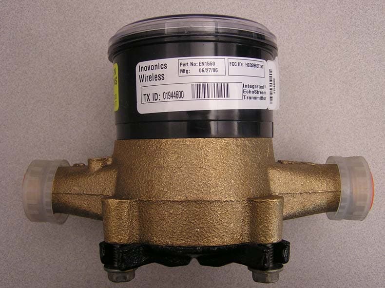
Click to zoom
Application Details
- Equipment Class
- DSS - Part 15 Spread Spectrum Transmitter
- Date of Grant
- Jun 18, 2007
- Application Purpose
- Original Equipment
- Date of Application
- Apr 24, 2007
- Equipment Note
- Integrated Water Meter with Transmitter
- Frequency Range
- 902.41000000 - 927.62000000
- Country
- United States
Documents & Files
Document Text
Text extracted from the exhibit documents filed with the FCC. Open a document above to read the original.
Users Manual
© 2006 Inovonics Wireless - www.inovonicswireless.comPage 1 EN1550 MetraMeter™ Installation and Operation Manual - 04672A 1 Overview The EN1550 combines the quality of a Neptune® T-10 water meter with the latest Inovonics Wireless EchoStream RF technology to provide an integrated meter transmitter for use in the TapWatch submetering system. 1.1 Inovonics Wireless Contact Information If you have any questions about this product, contact Inovonics Wireless technical services: • E-mail: [email protected] • Phone: (800) 782-2709; (303) 939-9336 1.2 EN1550 Components Figure 1 EN1550 Components 2 Installation and Startup 2.1 Install the Power Pack You must install the power pack for the EN1550 to function. To install the battery pack: 1. Carefully align the three power pack pins to the three holes in the top of the register and press down evenly, keeping the pins perpendicular to the holes. Caution: Install the power pack carefully. If the pins are not kept perpendicular with the register during installation, they may break. Never install the power pack at an angle. Figure 2 Install the Battery Pack 2. Snap the battery pack enclosure into place over the battery pack. Figure 3 Install the Battery Pack Enclosure 2.2 Install the Meter To install the meter: 1. Flush the service line to remove debris prior to installing the meter. 2. Install suitable inlet and outlet meter valves and couplings/setters if they are not already present. • Inovonics Wireless recommends installing a shut-off valve before the meter. • Ensure appropriate space is allowed in the line for the meter and two couple gaskets. The gap from gasket to gasket should be 7 1/2 inches. • Ensure the pipe ends are aligned so that the coupling and meter threads engage without binding or cross- threading. • Make sure to adhere to local plumbing codes and regulations. 3. Remove the meters thread protectors and spud caps. • Ensure no debris enters the meter during installation. 4. Place the coupling gaskets inside the coupling nuts and set the meter in the line. • For best results, install the meter in the horizontal position, with the register di l facing upward. • The direction of the flow marked on the meter must agree with the direction of water flow. 5. Start the coupling nuts by hand, then use a wrench to tighten. • Be careful not to cross-thread the connection. 6. Make sure to support the meter if plumbing it to PVC. A. Main caseB. RegisterC. Operation button D. Power packE. Security pin D B A C E Page 2© 2006 Inovonics Wireless - www.inovonicswireless.com 7. Slowly open the valve and run enough water to dissipate entrained air and flush the line. 8. Check to make sure the meter is indicating flow. 9. Check the meter for leaks. 2.3 Complete Installation After the meter has been installed: 1. Reset the transmitter. See “Send Reset Message” on page 2 for instructions. 2. Write down the odometer’s initial meter count for entry into the TapWatch 2 software. 3. Put the meter in rapid transmit mode. “Set Modes” on page 2 for instructions. 3 Operation/Maintenance 3.1 Remove the Power Pack If it is necessary to remove the power pack: 1. Lift the outside edge of the battery pack enclosure away and up from the register to remove it. 2. Use a flat blade screwdriver to evenly lift the battery pack away from the register at the points marked LIFT HERE. Caution: Remove the power pack carefully. If the pins are not kept perpendicular with the register during removal, they may break. Never remove the power pack by rocking it away from the register. Figure 4 Remove the Battery Pack 3.2 Rotate the Register If the odometer is difficult to read, the register can be rotated. Caution: The register should only be rotated if absolutely necessary. To rotate the register, you will need to purchase a new security pin from Inovonics Wireless. The security pin used in EN1550 is meant for one use only. 1. Use a punch to drive the security pin into the register (Fig. 1). 2. Turn the register 45 degress and lift it off of the meter. 3. Remove the broken security pin from the bottom of the register. 4. Replace the register in the desired position. 5. Use your thumb to insert a new security pin. Note: If you will need to rotate the register again, ensure there’s appropriate clearance to remove the security pin in the new position. 3.3 How to Read the Meter Figure 5 EN1550 Components Flow indicator The flow indicator spins when water is flowing through the meter. Odometer The odometer displays the number of gallons used, to the nearest 10 gallons. Sweep hand The sweep hand indicates the single digit number of gallons that has passed through the meter. Each full revolution indicates 10 gallons of consumption, and will advance the first column on the odometer. The meter in Figure 5 shows a consumption of 14.6 gallons. The odomoter indicates that 10 gallons have been used, and the sweep hand adds 4.6 gallons to that number. 3.4 Send Reset Message When the EN1550 is reset, the count is zeroed and an RF reset message is sent. The RF reset message is used for registration into TapWatch software. To reset the EN1550: 1. Push an unfolded paper clip through the guide hole to press and hold the Operation button for five seconds (Figure 2). 3.5 Set Modes In normal mode, the EN1550 transmits the flow count approximately once per hour, or upon every 100 gallons of water, whichever occurs first. When in rapid transmit mode, the EN1550 transmits the flow count approximately once per minute. Rapid transmit mode is used during installation, to help ensure all your programmed end- devices are functioning correctly. A. Flow indicatorB. OdometerC. Sweep hand B A C © 2006 Inovonics Wireless - www.inovonicswireless.comPage 3 Once in rapid transmit mode, the EN1550 transmits for approximately 36 hours, and then returns to normal mode. The EN1550 can also be returned to normal mode by resetting it. This will also reset the count to zero. To set rapid transmit mode: 1. Push an unfolded pa…
Text truncated - open the document above for the full version.
Cover Letter(s)
April 24, 2007 Federal Communications Commission Authorization and Standards Division 7435 Oakland Mills Road Columbia, MD 21046 Subject: Request for Confidentiality for FCC ID# HCQ3B6ETIMT Gentlemen: The following reports are marked confidential, and should be maintained in the non- public file. This confidentiality is necessary to protect proprietary information contained within these sections of the application for Certification. 1) Operational Description 2) Schematics 3) Block Diagram Thanks for your help. Sincerely, Joni Ripper Engineering Assistant Inovonics Wireless Corp. 303-209-7260 [email protected]
External Photos
FCC ID: HCQ3B6ETIMT EN1550 4. External Photos: Unit Installed on Brass Water Meter Top of Unit FCC ID: HCQ3B6ETIMT EN1550 External Photos (cont’) Unit Installed on Brass Water Meter – side view FCC Label
ID Label/Location Info
FCC ID: HCQ3B6ETIMT EN1550 FCC LABEL FCC ID: HCQ3B6ETIMT EN1550 FCC LABEL Page 2 of 3 FCC ID: HCQ3B6ETIMT EN1550 FCC LABEL Page 3 of 3
Internal Photos
FCC ID: HCQ3B6ETIMT EN1550 6. Internal photos: PCB Front PCB Front without Shield Can FCC ID: HCQ3B6ETIMT EN1550 Page 2 Internal Photos (cont’) PCB Back
Test Report
Successor in interest to International Approval Laboratories EMC EMISSIONS - TEST REPORT (In-Part) Test Report No. 3092807-1 Issue Date: Friday, March 10, 2006 Model / Serial No. MN: EN1550/SN: 01619484 Product Type Water Meter Transmitters. Client Inovonics Wireless Corp. Manufacturer Inovonics Wireless Corp. License holder Inovonics Wireless Corp. 315 CTC Blvd Address Louisville, CO 80027 Test Criteria Applied FCC CFR47 Part 15.247 Test Result PASS Test Project Number References 3092807 Total Pages Including Appendices: 36 Title 47 CFR 15: RADIO FREQUENCY DEVICES Reviewed By : Mike Spataro Approved By : INTERTEK ETL SEMKO (ITS) reports apply only to the specific samples tested under stated test conditions. It is the manufacturer's responsibility to assure that additional production units of this model are manufactured with identical electrical and mechanical components. ITS have no liability for any deductions, inferences or generalizations drawn by the client or others from IAL issued reports. This report is the confidential property of the client. As a mutual protection to our clients, the public and ourselves, extracts from the test report shall not be reproduced except in full without our written approval of ITS. This report shall not be used by the client to claim product endorsement by NVLAP (No. 200624- 0) or any agency of the US government. Intertek ETL Semko and its professional staff hold government and professional organization certifications and are members of IEEE, NVLAP, and VCCI. Lab Code:200264-0 The entity logos above are for reference only and may not apply to this test report. Project File: 3092807 Page 2 of 36 Intertek ETL Semko 5541 Central Avenue, Suite 110 Boulder, Colorado 80301 Voice: 303 786 7999 Fax: 303 449 6160 Rev.No 1 D I R E C T O R Y Documentation Page(s) Test report 1 - 36 Directory 2 Test Regulations 3 General Remarks 4-5 Test-setup Photographs 6 - 9 Appendix A Test Data Sheets and Test Equipment Used 10 - 21 Appendix B Test Plan/Constructional Data Form 22 - 31 Appendix C Measurement Protocol/Test Procedures 32 - 36 STATEMENT OF MEASUREMENT UNCERTAINTY The data and results referenced in this document are true and accurate. The measurement uncertainty for Conducted Emissions in the frequency range of 150kHz – 30MHz is calculated to be ±2.30dB and for Radiated Emissions is calculated to be ±3.60dB in the frequency range of 30MHz – 200MHz and ±3.38dB in the frequency range of 200MHz – 1000MHz. EUT Received Date: 28-Feb-2006 Testing Start Date: 28-Feb-2006 Testing End Date: 2-March-2006 Project File: 3092807 Page 3 of 36 Intertek ETL Semko 5541 Central Avenue, Suite 110 Boulder, Colorado 80301 Voice: 303 786 7999 Fax: 303 449 6160 Rev.No 1 The tests were performed according to following regulations : 1. FCC CFR47 Part 15.205 2. FCC CFR47 Part 15.207 3. FCC CFR47 Part 15.209 4. FCC CFR47 Part 15.247 5. ICES-003 Emission Test Results: Conducted Emissions, Powerline (15.207) - Not Applicable Test Result Minimum limit margin NA dB at NA MHz Maximum limit exceeding dB at MHz Remarks: Radiated Emissions (15.209) - PASS Test Result Minimum limit margin -5.7 dB at 1000.00 MHz Maximum limit exceeding dB at MHz Remarks: Radiated Emissions (15.205)/(15.247) (c) - PASS Test Result Minimum limit margin -0.32 dB at 2782.69 MHz Maximum limit exceeding dB at MHz Remarks: Emissions is from model: ES1501 on the mid channel Peak Output Power 15.247 (b)(2) - PASS Test Result Minimum limit margin -5.3 dB at 902.41 MHz Maximum limit exceeding dB at MHz Remarks: Project File: 3092807 Page 4 of 36 Intertek ETL Semko 5541 Central Avenue, Suite 110 Boulder, Colorado 80301 Voice: 303 786 7999 Fax: 303 449 6160 Rev.No 1 GENERAL REMARKS: The following remarks are to be considered as “where applicable“ and are taken into account while completing any FCC/IC/ETSI radio tests at Intertek, ETL Semko. Testing was performed in 3 different orthogonal axis to determine the worst case emissions from the device. The worst case emissions measurements are shown in this report. FCC CFR47 Part 15.31: Measurement Standards: In any case where the device is powered off a battery, a fresh battery was used during test. In cases where the device is powered off an AC supply, voltage was varied per Part 15.31 to find worst case emissions. FCC CFR47 Part 15.35: Measurement Detector Functions and Bandwidths: FCC Part 15.35 was utilized when performing the measurements within this report. This test report is in-part, Intertek ETL Semko was asked to test only the field strength of the fundamental and harmonics as well as the unintentional radiated emissions and conducted emissions when applicable. Modifications required to pass: None Test Specification Deviations: Additions to or Exclusions from: None Project File: 3092807 Page 5 of 36 Intertek ETL Semko 5541 Central Avenue, Suite 110 Boulder, Colorado 80301 Voice: 303 786 7999 Fax: 303 449 6160 Rev.No 1 Required Information In Accordance to FCC CFR 47 Part 2.1033: Exhibits Including (where applicable): 1. Users Manual 2. Operation Description 3. Block Diagram 4. Report of Measurement 5. External & Internal Photographs 6. Schematic 7. Parts List 8. Tuning Procedure (if applicable) 9. Test Setup Photograph 10. Label Drawings and or Photograpghs 11. Description of Support Equipment (where Applicable) Required Information in Accordance to Industry Canada Regulations (In addition to the above): Information Required Description Comments Modulation Type (i.e. ASK, NON, FSK, DSSS, FHSS, etc.) Emissions Designator Per TRC-49 In Country Representative Contact Information 99% Bandwidth Measurement Per RSS-210 Rule Part 11, 15 & 18 Devices Other Rule Part Devices Description Comments 2.1033(b)(1) 2.1033(c)(1) Manu. Contact See Page 1 of this report 2.1033(b)(2) 2.1033(c)(2) FCC Identifier 2.1033(b)(3) 2.1033(c)(3) Users Manual to include Operating, installation Attached as Exhibit 2.1033(c)(4) Emissions Designator per 2. 2.1033(c)(5) Frequency Range Not Applicable to Pa…
Text truncated - open the document above for the full version.
Test Report
FCC ID: HCQ3B6ETIMT EN1550 12. Test Report Additional Information The test report containing intentional/unintentional emissions data is attached as “TestReport_EN1550.pdf”. Intertek ETL Semko labs generated this report. Additional data demonstrating compliance with 47CFR15.247 follows. For the following measurements, the antenna was replaced by a coaxial connection to an HP8594E spectrum analyzer. Minimum Channel Separation: Plot 1 is a spectrum plot showing a minimum channel separation of 810 kHz. Compliance with section 15.247(a)(1) is demonstrated by capturing several transmissions over a small portion of the 902-928 MHz ISM band. Plot 1: Demonstration of channel spacing requirement. FCC ID: HCQ3B6ETIMT EN1550 Number of hopping Channels: Plot 2 demonstrates compliance with 15.247(a)(1)(i) — Number of hopping channels. This is a stored display of many sequential transmissions to show the overall band occupied by the transmitter Plot 2: Demonstration of 25 hopping channels. 20 dB bandwidth of a single channel: Plot 3 shows the 20 dB bandwidth of a single channel to demonstrate compliance with 15.247(a)(1)(i). The 20 dB occupied bandwidth is 276.3 kHz. Plot 3: Demonstration of occupied bandwidth.
Test Setup Photos
FCC ID: HCQ3B6ETIMT ES1550 TEST SETUP PHOTOS FCC ID: HCQ3B6ETIMT EN1550 TEST SETUP PHOTOS Page 2 of 3 FCC ID: HCQ3B6ETIMT EN1550 TEST SETUP PHOTOS Page 3 of 3
Contact Information
Applicant
Jess Cobb(Manager of Program Mgmt)
Technical Contact
Inovonics Wireless CorpDave Henke
[email protected]303-209-7163
315 CTC Blvd · Louisville, Colorado · United States
Non-Technical Contact
Inovonics Wireless CorpJoni Ripper
[email protected]303-209-7260
Test Firm
Intertek Testing Services NA, Inc.Jay Kogoma
Technical Specifications
| # | Rule Parts | Frequency Range | Power Output |
|---|---|---|---|
| 1 | 15C | 902.41 MHz - 927.62 MHz | 70.00 mW |
Other Applications from Inovonics Wireless Corporation

HCQ-IDTOUCH1
May 13, 2026Inovonics Wired Touchscreen Keypad
Equipment Class
DTS - Digital Transmission System
HCQBWA02
Aug 28, 2024Flush Mount Locator
Equipment Class
DSS - Part 15 Spread Spectrum Transmitter
HCQTBA
Sep 21, 2022TBA Module
Equipment Class
DSS - Part 15 Spread Spectrum Transmitter
HCQPFA01
Jul 14, 2022Fall Detect Transmitter
Equipment Class
DSS - Part 15 Spread Spectrum Transmitter
HCQ3B6BRGSA
Sep 22, 2020Bluetooth to EchoStream Bridge
Equipment Class
DTS - Digital Transmission System