HCQ3B6ETPMTSubmetering Transmitter
Inovonics Wireless Corporation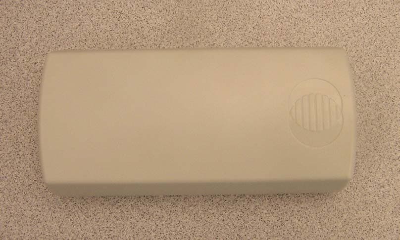
Click to zoom
Application Details
- Equipment Class
- DSS - Part 15 Spread Spectrum Transmitter
- Date of Grant
- Sep 14, 2006
- Application Purpose
- Original Equipment
- Date of Application
- Jun 08, 2006
- Equipment Note
- Submetering Transmitter
- Frequency Range
- 902.41000000 - 927.62000000
- Country
- United States
Documents & Files
Document Text
Text extracted from the exhibit documents filed with the FCC. Open a document above to read the original.
Users Manual
© 2005 Inovonics Wireless - www.inovonicswireless.com ES1501/EN1501-XL EchoStream ® TapWatch ® Transmitter Installation and Operation Manual - 04590A 1 Overview Connected to pulse-output meters being used for multi-family submetering, the ES1501 and EN1501-XL transmitters will transmit data to an RF receiver that is connected to a Data Concentrator and Communicator (DCC-5800). The ES1501 includes a replaceable battery; the EN1501-XL includes a long- life battery that is not replaceable. 1.1 Inovonics Wireless Contact Information If you have any problems with this procedure, contact Inovonics Wireless technical services: • E-mail: [email protected] • Phone: (800) 782-2709; (303) 939-9336 1.2 ES1501/EN1501-XL Components Figure 1 ES1501/EN1501-XL Components 2 Installation and Startup 2.1 Connect Transmitter to Meter Connect the transmitter to the meter as follows: 1. Open the housing by pressing down on the base tab near the wiring thru-hole while lifting away the cover. 2. Fully insert stripped wires into the removable header terminal. 3. Use a small Phillips screwdriver to tighten the screws that secure wires to the removable header terminal. 4. Attach removable header terminal (if removed) to the transmitter board as shown. Note: If connecting to a meter that has polarity to its pulse output, the negative (—) should be connected to the outside terminal, closest to the corner of the board. Figure 2 Connect the Transmitter to the Meter 2.2 Select Frequency Band If you are using either transmitter anywhere except North America, you will need to select the frequency band for your geographic area. If you are using the transmitter in North America, there is no need to select the frequency band. All transmitters are set for North America by default. Select Frequency Band on the ES1501 1. Place the selection jumper included in the accessory pack on the appropriate frequency band selection pins (Figure 1). • Leave the jumper off the pins to select 902-928 MHz for North America. • Place the jumper on the left two pins to select 921-928 MHz for New Zealand. • Place the jumper on the middle two pins to select 868-869 MHz for Europe. • Place the jumper on the right two pins to select 915-928 MHz for Australia. Select Frequency Band on the EN1501-XL 1. Place the selection jumper included in the accessory pack on the appropriate frequency band selection pins (Figure 1). • Leave the jumper off the pins to select 902-928 MHz for North America. • Place the jumper on the left two pins to select 921-928 MHz for New Zealand. • The selection marked EU is non-functional on the EN1501- XL. Do not select the middle two pins. • Place the jumper on the right two pins to select 915-928 MHz for Australia. 2.3 Mount the Transmitter 1. Use the double-sided tape to mount the transmitter to a clean wall. 2. If installing the ES1501, the transmitter can be secured a wall with the mounting screw and anchor. Remove the battery to access the mounting screw hole; press the reset button after replacing the battery. A. Battery (ES1501- style battery shown) B. Tamper switchC. Removable header terminal D. Frequency band selection pins E. Reset button C A B E D A. Cabling thru-holeB. Removable header terminal A B Note: Ensure cabling enters the housing through the access wiring thru-hole, and replace the housing (Figure 2). Figure 3 Mount the Transmitter 2.4 Register the Transmitter Note: See “Programming the PMT-Meter Pair” in TapWatch User Manual for more information. 1. Confirm that transmitter is connected to the meter. 2. Confirm that the battery is installed. 3. Go to the “Registered Meters” tab of the Site Information editor. 4. Click “Add” on the “Registered Meters” page; confirm selected building. 5. Complete the “Add New Meter To...” form when it appears. 6. Click the “Register” button. 7. When prompted, press the reset button on the transmitter; wait for confirmation. 3 Replace the Battery (ES1501 Only) When the low battery message is received, you will need to replace the ES1501 battery. 1. Open the housing by pressing down on the base tab near the wiring thru-hole while lifting away the cover. 2. Remove the old battery, taking note of the battery orientation. 3. Insert the new battery, making sure it is aligned correctly. 4. Press the reset button. Note: ES1501 transmitters retain programming data in non- volatile memory. They do not require reprogramming after loss of power. Install new battery and press the transmitter reset button to re-initialize the transmitter and restore programming. Its count will go to zero and the initial Meter Read count will be updated in the DCC. 4 Specifications Dimensions: 3.57" x 1.70" x 0.85" Operating environment: 0°- 60°C (32°- 140°F), 90% relative humidity, non-condensing Typical battery life: ES1501: 5 years at 70 to 90°F (20 to 30°C). Higher temperatures reduce battery life. EN1501-XL: calculated battery life of 20 years at 70 to 90°F (20 to 30°C). Higher temperatures reduce battery life. ES1501 Battery (BAT604): 3.0V lithium (DL123A) The battery is always supervised. 5 Warranty/Disclaimer Caution: Changes or modifications to this unit not expressly approved by Inovonics Wireless Corporation may void the installer's authority to operate the equipment as well as the product warranty. Inovonics Wireless Corporation (“Inovonics”) warrants its products (“Product” or “Products”) to conform to its own specifications and to be free of defects in materials and workmanship under normal use for a period of fourteen (14) months from the date of manufacture. Within the warranty period, Inovonics will repair or replace, at its option, all or any part of the warranted Product. Inovonics will not be responsible for dismantling and/or reinstallation charges. To exercise the warranty, the User (“User”, “Installer” or “Consumer”) must work directly through their authorized distributor who will be given a Return Material Authorization (“RMA”) number by Inovonics. Details of shipment will be ar…
Text truncated - open the document above for the full version.
Cover Letter(s)
April 24, 2006 Federal Communications Commission Authorization and Standards Division 7435 Oakland Mills Road Columbia, MD 21046 Subject: Request for Confidentiality for FCC ID# HCQ3B6ETPMT Gentlemen: The following reports are marked confidential, and should be maintained in the non- public file. This confidentiality is necessary to protect proprietary information contained within these sections of the application for Certification. 1) Operational Description 2) Schematics 3) Block Diagram Thanks for your help. Sincerely, Joni Ripper Engineering Assistant Inovonics Wireless Corp. 303-209-7260 [email protected]
External Photos
FCC ID: HCQ3B6ETPMT ES1501 4. External Photos: Bottom View FCC Label Top View
ID Label/Location Info
CONFIDENTIAL DOCUMENT ES1501 FCC-CE Label 04589B CONFIDENTIAL DOCUMENTATION The information contained in this document is confidential to and the sole property of Inovonics Corporation. Receipt of this information requires the existence and full acceptance of the terms and conditions of a Non Disclosure Agreement signed by the Inovonics Corporation and the Recipient. This documentation is not to be reproduced or redistributed except as provided in the Non Disclosure Agreement. MATERIAL:.002" THICK WHITE MYLAR WITH .001" GLOSSY LAMINATION (FOR PROTECTION FROM INK SMEARING) AND PERMANENT ADHESIVE APPLIED TO THE BACKSIDE ARTWORK:SUPPLIED BY INOVONICS TEXT: BLACK LABEL SIZE: 1.220" X .0.455" (SHOWN TO 3 TIMES SCALE), “SHARP CORNERS” AND NO BORDER PACKAGING AND LABEL ORIENTATION:LABELS TO BE SUPPLIED ON TOP SIDE OF ROLL STOCK WITH TEXT READABLE AS VIEWED FROM BOTTOM (SHORT) EDGE OF ROLL Rev. Level DescriptionDate AInitial Release10/21/2005 BAdded WEEE Label10/25/2005 Confidential to InovonicsES150104589_qxd FCC ID HCQ3B6ETPMT ES1501 www.inovonics.com
Internal Photos
FCC ID: HCQ3B6ETPMT ES1501 6. Internal photos: PCB front side, showing RF shielding and antenna PCB front side, without shield can and antenna FCC ID: HCQ3B6ETPMT EN1501 Page 2 PCB back side
Test Report
Successor in interest to International Approval Laboratories EMC EMISSIONS - TEST REPORT (In-Part) Test Report No. 3090365-1 Issue Date: Tues. Jan. 31, 2006 Model / Serial No. ES1501, ES1501-XL/ 01564224, 01564072 Product Type Water Meter Transmitters. Client Inovonics Wireless Corp. Manufacturer Inovonics Wireless Corp. License holder Inovonics Wireless Corp. 315 CTC Blvd Address Louisville, CO 80027 Test Criteria Applied FCC CFR47 Part 15.247 Test Result PASS Test Project Number References 3090365 Total Pages Including Appendices: 45 Title 47 CFR 15: RADIO FREQUENCY DEVICES Reviewed By : Mike Spataro Approved By : INTERNATIONAL APPROVALS LABORATORIES (IAL) reports apply only to the specific samples tested under stated test conditions. It is the manufacturer's responsibility to assure that additional production units of this model are manufactured with identical electrical and mechanical components. IAL have no liability for any deductions, inferences or generalizations drawn by the client or others from IAL issued reports. This report is the confidential property of the client. As a mutual protection to our clients, the public and ourselves, extracts from the test report shall not be reproduced except in full without our written approval of IAL. This report shall not be used by the client to claim product endorsement by NVLAP (No. 200624- 0) or any agency of the US government. International Approval Laboratories and its professional staff hold government and professional organization certifications and are members of IEEE, NVLAP, and VCCI. Lab Code:200264-0 The entity logos above are for reference only and may not apply to this test report. Project File: 3090365 Page 2 of 45 Intertek ETL Semko 5541 Central Avenue, Suite 110 Boulder, Colorado 80301 Voice: 303 786 7999 Fax: 303 449 6160 Rev.No 1 D I R E C T O R Y Documentation Page(s) Test report 1 - 45 Directory 2 Test Regulations 3 General Remarks 4-5 Test-setup Photographs 6 - 10 Appendix A Test Data Sheets and Test Equipment Used 11 - 30 Appendix B Test Plan/Constructional Data Form 31 - 40 Appendix C Measurement Protocol/Test Procedures 41 - 45 STATEMENT OF MEASUREMENT UNCERTAINTY The data and results referenced in this document are true and accurate. The measurement uncertainty for Conducted Emissions in the frequency range of 150kHz – 30MHz is calculated to be ±2.30dB and for Radiated Emissions is calculated to be ±3.60dB in the frequency range of 30MHz – 200MHz and ±3.38dB in the frequency range of 200MHz – 1000MHz. EUT Received Date: 5-Jan-2006 Testing Start Date: 5-Jan-2006 Testing End Date: 7-Jan-2006 Project File: 3090365 Page 3 of 45 Intertek ETL Semko 5541 Central Avenue, Suite 110 Boulder, Colorado 80301 Voice: 303 786 7999 Fax: 303 449 6160 Rev.No 1 The tests were performed according to following regulations : 1. FCC CFR47 Part 15.205 2. FCC CFR47 Part 15.207 3. FCC CFR47 Part 15.209 4. FCC CFR47 Part 15.247 5. ICES-003 Emission Test Results: Conducted Emissions, Powerline (15.207) - Not Applicable Test Result Minimum limit margin NA dB at NA MHz Maximum limit exceeding dB at MHz Remarks: Radiated Emissions (15.209) - PASS Test Result Minimum limit margin -5.4 dB at 1159.61 MHz Maximum limit exceeding dB at MHz Remarks: Radiated Emissions (15.205)/(15.247) (c) - PASS Test Result Minimum limit margin -3.92 dB at 2744.28 MHz Maximum limit exceeding dB at MHz Remarks: Emissions is from model: ES1501 on the mid channel Peak Output Power 15.247 (b)(2) - PASS Test Result Minimum limit margin -1.7 dB at 902.37 MHz Maximum limit exceeding dB at MHz Remarks: Emissions is from model: ES1501-XL on the low channel Project File: 3090365 Page 4 of 45 Intertek ETL Semko 5541 Central Avenue, Suite 110 Boulder, Colorado 80301 Voice: 303 786 7999 Fax: 303 449 6160 Rev.No 1 GENERAL REMARKS: The following remarks are to be considered as “where applicable“ and are taken into account while completing any FCC/IC/ETSI radio tests at Intertek, ETL Semko. Testing was performed in 3 different orthogonal axis to determine the worst case emissions from the device. The worst case emissions measurements are shown in this report. FCC CFR47 Part 15.31: Measurement Standards: In any case where the device is powered off a battery, a fresh battery was used during test. In cases where the device is powered off an AC supply, voltage was varied per Part 15.31 to find worst case emissions. FCC CFR47 Part 15.35: Measurement Detector Functions and Bandwidths: FCC Part 15.35 was utilized when performing the measurements within this report. This test report is in-part, Intertek, ETL Semko was asked to test only the field strength of the fundamental and harmonics as well as the unintentional radiated emissions and conducted emissions when applicable. This report covers two models of the same family of products. Intentional emissions, fundamental and harmonics, was completed on each unit separately. Unintentional emissions were completed on the two units at the same time. Modifications required to pass: None Test Specification Deviations: Additions to or Exclusions from: None Project File: 3090365 Page 5 of 45 Intertek ETL Semko 5541 Central Avenue, Suite 110 Boulder, Colorado 80301 Voice: 303 786 7999 Fax: 303 449 6160 Rev.No 1 Required Information In Accordance to FCC CFR 47 Part 2.1033: Exhibits Including (where applicable): 1. Users Manual 2. Operation Description 3. Block Diagram 4. Report of Measurement 5. External & Internal Photographs 6. Schematic 7. Parts List 8. Tuning Procedure (if applicable) 9. Test Setup Photograph 10. Label Drawings and or Photograpghs 11. Description of Support Equipment (where Applicable) Required Information in Accordance to Industry Canada Regulations (In addition to the above): Information Required Description Comments Modulation Type (i.e. ASK, NON, FSK, DSSS, FHSS, etc.) Emissions Designator Per TRC-49 In Country Representative Contact Information 99% Bandwidth Measurement Per RSS-210 Rule Part 11, 15 & 18 Devices Other Rule Pa…
Text truncated - open the document above for the full version.
Test Report
FCC ID: HCQ3B6ETPMT ES1501 12. Test Report Additional Information The test report containing intentional/unintentional emissions data is attached as “3090365-1.pdf”. Intertek ETL Semko labs generated this report. Additional data demonstrating compliance with 47CFR15.247 follows. For the following measurements, the antenna was replaced by a coaxial connection to an HP8594E spectrum analyzer. Minimum Channel Separation: Plot 1 is a spectrum plot showing a minimum channel separation of 810 kHz. Compliance with section 15.247(a)(1) is demonstrated by capturing several transmissions over a small portion of the 902-928 MHz ISM band. Plot 1: Demonstration of channel spacing requirement. FCC ID: HCQ3B6ETPMT ES1501 Number of hopping Channels: Plot 2 demonstrates compliance with 15.247(a)(1)(i) — Number of hopping channels. This is a stored display of many sequential transmissions to show the overall band occupied by the transmitter Plot 2: Demonstration of 25 hopping channels. 20 dB bandwidth of a single channel: Plot 3 shows the 20 dB bandwidth of a single channel to demonstrate compliance with 15.247(a)(1)(i). The 20 dB occupied bandwidth is 261 kHz. Plot 3: Demonstration of occupied bandwidth.
Test Setup Photos
FCC ID: HCQ3B6ETPMT ES1501 TEST SETUP PHOTOS FCC ID: HCQ3B6ETPMT EN1501 TEST SETUP PHOTOS Page 2 of 4 FCC ID: HCQ3B6ETPMT EN1501 TEST SETUP PHOTOS Page 3 of 4 FCC ID: HCQ3B6ETPMT EN1501 TEST SETUP PHOTOS Page 4 of 4
Contact Information
Applicant
Jess Cobb(Manager of Program Mgmt)
Technical Contact
Inovonics Wireless CorporationDave Henke
[email protected]1-800-782-2709
315 CTC Blvd · Louisville, Colorado · United States
Non-Technical Contact
Inovonics Wireless CorporationJoni Ripper
[email protected]1-800-782-2709
Test Firm
Intertek Testing Services NA, Inc.Jay Kogoma
Technical Specifications
| # | Rule Parts | Frequency Range | Power Output |
|---|---|---|---|
| 1 | 15C | 902.41 MHz - 927.62 MHz | 140.00 mW |
Other Applications from Inovonics Wireless Corporation

HCQ-IDTOUCH1
May 13, 2026Inovonics Wired Touchscreen Keypad
Equipment Class
DTS - Digital Transmission System
HCQBWA02
Aug 28, 2024Flush Mount Locator
Equipment Class
DSS - Part 15 Spread Spectrum Transmitter
HCQTBA
Sep 21, 2022TBA Module
Equipment Class
DSS - Part 15 Spread Spectrum Transmitter
HCQPFA01
Jul 14, 2022Fall Detect Transmitter
Equipment Class
DSS - Part 15 Spread Spectrum Transmitter
HCQ3B6BRGSA
Sep 22, 2020Bluetooth to EchoStream Bridge
Equipment Class
DTS - Digital Transmission System