HCQ3B6ETTHMWireless Temperature Sensor
Inovonics Wireless Corporation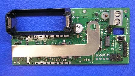
Click to zoom
Application Details
- Equipment Class
- DSS - Part 15 Spread Spectrum Transmitter
- Date of Grant
- Mar 15, 2005
- Application Purpose
- Original Equipment
- Date of Application
- Dec 01, 2004
- Equipment Note
- Wireless Temperature Sensor
- Frequency Range
- 902.40000000 - 927.60000000
- Country
- United States
Documents & Files
Document Text
Text extracted from the exhibit documents filed with the FCC. Open a document above to read the original.
Users Manual
Garantía y Exención de ResponsabilidadInovonics Wireless Corporation ("Inovonics") garantiza que sus pro-ductos (el "Producto" o los "Productos") cumplen sus propiasespecificaciones y están libres de defectos en los materiales y de fabricación para su uso normal durante un períodode 24 meses a partir de la fecha de fabricación. Dentro del períodode garantía, Inovonics reparará o sustituirá, según decida, la totali-dad o alguna parte del Producto en garantía. Inovonics no seresponsabiliza de los gastos de desmontaje y/o reinstalación. Paraejercitar la garantía, el Usuario (el "Usuario","Instalador" o"Consumidor") deberá proceder directamente a través de su distribuidor autorizado a quienInovonics entregará un número de Autorización de Devolución deMaterial ("RMA"). Los detalles del envío se acordarán directamentemediante el distribuidor autorizado.La presente garantía será nula en los casos de instalación inade-cuada, uso inadecuado, incumplimiento de las instrucciones de instalación y funcionamiento, alteración, accidente o manipulación y reparación por parte de cualquier per-sona ajena a Inovonics. La presente garantía es exclusiva y sustituye expresamente todaslas demás garantías, obligaciones o responsabilidades, tantoescritas como orales, expresas o implícitas. Inovonics no garantiza que el producto de Inovonics sea comercializable o adecuado para una finalidad concreta, ni tampocoexiste ninguna otra garantía expresa o implícita aparte de la que sedispone expresamente en el presente documento. Inovonics no será responsable en ningún caso de losdaños derivados, incidentales, especiales o punitivos, incluidos, con carácter enunciativo pero no limitativo, las pérdidas de beneficios, ingresos o contratos, las pérdidas de uso, elcoste del tiempo de parada, o la interrupción de las actividades, nitampoco de ninguna reclamación realizada por los clientes del dis-tribuidor o cualquier otra persona o entidad. La presente garantía no podrá modificarse ni ampliarse. Inovonicsno autoriza a ninguna persona a actuar en su nombre en la ampliación o modificación de la presente garantía. La presente garantía se aplicará exclusivamente a losProductos de Inovonics. Inovonics baterías no será responsable delos daños derivados, incidentales o resultantes o de las pérdidas decualquier tipo que se produzcan por el mal funcionamiento delProducto provocado por los productos, accesorios o complementosde otros fabricantes, incluidas las baterías, que se utilicen juntocon los Productos de Inovonics. Envíe un mensaje de correo electrónico a [email protected] para obtener una copia de la "Declaración de Conformidad" CE. L Clausola di Garanzia e Negazione diResponsabilitaInovonics Wireless Corporation ("Inovonics") garantisce che i propriprodotti sono conformi alle proprie specifiche e sono privi di difettidi materiale e di produzione nelle normali condizioni d'uso, per un periodo di 24 mesi a partire dalla data difabbricazione. Durante il periodo di garanzia, Inovonics si impegnaa riparare o a sostituire, a sua sola discrezione, il prodotto ingaranzia o qualsiasi parte del medesimo. Inovonics declina ogni responsabilità circa le spese dismantellamento e/o reinstallazione. Per poter godere della garanzia,l'utente ("utente", "installatore" o "consumatore") deve lavoraretramite il rispettivo distributore autorizzato che riceverà daInovonics il numero RMA (autorizzazione a restituire il materiale). I dati di spedizione sono predisposti tramiteil distributore autorizzato.La presente garanzia risulta non valida in caso di installazioneinadeguata, di utilizzo non conforme, di mancata osservanza delleistruzioni per l'installazione e il funzionamento, modifiche, incidenti e manomissione, riparazioni non eseguite daInovonics. La presente garanzia deve essere considerata esclusiva ed espressa-mente sostitutiva di tutti gli altri obblighi e di tutte le altregaranzie e responsabilità, vuoi scritti, orali, vuoi impliciti o esplici-ti. Inovonics non garantisce che il prodotto Inovonics sia commer-ciabile o adatto a qualsivoglia scopo particolare e che esista un'altra garanzia, implicita o esplicita,diversa da quanto espressamente ivi stipulato. In nessuna circostanza Inovonics è responsabile di danni occasionali, diretti,indiretti, speciali o risarcimenti esemplari, inclusivi di mancato profitto, mancate entrate e mancato contratto, mancatoutilizzo, costi da tempo di inattività, nonché di qualsivoglia richiesta di risarcimento inoltrata dai clienti del dis-tributore o da qualsivoglia altra persona o entità. La presente garanzia non sarà modificata o dilazionata. Inovonicsnon autorizza alcuna persona a rappresentare Inovonics e quindi amodificare o dilazionare la presente garanzia. La presente garanziaè valida solo per i prodotti Inovonics. Inovonics declina ogniresponsabilità in caso di danni e perdite, diretti, indiretti e occa-sionali, di qualsiasi genere, dovuti al malfunzionamento del prodot-to a causa di prodotti, accessori e accessori in dotazione di altrecase produttrici, comprese le batterie, utilizzati assieme ai prodottiInovonics. Per una copia della "dichiarazione di conformità CE", inviare una e-mail all indirizzo [email protected]. L Garantie/DéchargeInovonics Wireless Corporation ("Inovonics") garantit que ses pro-duits ("Produit" ou "Produits") sont conformes aux caractéristiquesindiquées et qu'ils ne présentent pas de défaut de matériel ou demain-d'œuvre dans des conditions d'utilisation normale pendantune période de 24 mois à partir de la date de fabrication. Au coursde la période de garantie, Inovonics réparera ou remplacera, à sonchoix, la totalité ou partie du Produit sous garantie. Inovonics nesera pas responsable des coûts de montage et/ou réinstallation.Pour bénéficier de sa garantie, l'Utilisateur ("Utilisateur","Installateur" où "Consommateur") devra traiter directement avecson distributeur agréé à qui Inovonics fournira un numéro d'autori-sation de retour de matériel ("RMA"). L'organisation de…
Text truncated - open the document above for the full version.
Cover Letter(s)
November 30, 2004 Federal Communications Commission Authorization and Standards Division 7435 Oakland Mills Road Columbia, MD 21046 Subject: Request for Confidentiality for FCC ID# HCQ3B6ETTHM Gentlemen: The following reports are marked confidential, and should be maintained in the non- public file. This confidentiality is necessary to protect proprietary information contained within these sections of the application for Certification. 1) Operational Description 2) Schematics 3) Block Diagram Thanks for your help. Sincerely, Donald J. Hume President
Cover Letter(s)
March 4, 2005 Federal Communications Commission OET Equipment Authorization Electronic Filing Attn: Processing Staff Re: FCC ID: HCQ3B6ETTHM 731 CONFIRMATION #: EA753808 CORRESPONDENCE REFERENCE #: 28528 Dear Processing Staff: This message is to inform you that today through the “Add Attachments” link I submitted an additional exhibit pertaining to the above-referenced application. The exhibit is entitled “Transmitter Band Selection – ES1723”. Please contact me if you have any questions. Thank you. Sincerely, Joni Ripper Engineering Assistant Phone: 303-209-7260 Email: [email protected]
Cover Letter(s)
Band Select Jumper Operation In EchoStream Transmitters February 16, 2005 Inovonics’ EchoStream transmitter products, Certified under 15.247, are used to monitor various conditions ranging from the status of a switch to temperature measurements. This status information or data payload is combined in the transmitter with unique point ID and battery status and is transmitted to a compatible EchoStream receiver. The systems are always professionally installed and each transmitter must be “registered” to the receiver at the time of system set-up otherwise the system will not function. Careful consideration was given to a product line configuration that would prevent intentional or inadvertent operation of the system outside of the 902 – 928 MHz band in the United States. Receivers operating in the 868 - 870 MHz European band are sold only in the European Union market. The EchoStream receivers sold in the United States are capable of operation only in the 902 – 928 MHz band. They can register and receive transmitters operating only on the 25 designated hopping frequencies within the 902 – 928 MHz band (see channel plan below). The transmitters are shipped without a band-select jumper installed and they default to the U.S. 902 – 928 MHz band. If a dealer installing the system were to place a jumper in the transmitter’s EU position mistakenly, the receiver could not be made to register the transmitter or to function at all. EchoStream Channel Plan Step # Frequency Step # Frequency 1 909.6 14 926.4 2 914.8 15 925.6 3 912.8 16 917.2 4 910.8 17 927.6 5 912.0 18 923.2 6 903.6 19 924.4 7 921.2 20 904.4 8 902.4 21 919.2 9 914.0 22 918.0 10 908.8 23 905.6 11 907.6 24 916.0 12 920.4 25 922.4 13 906.4
Cover Letter(s)
Band Select Jumper Operation In EchoStream Transmitters February 16, 2005 Inovonics’ EchoStream transmitter products, Certified under 15.247, are used to monitor various conditions ranging from the status of a switch to temperature measurements. This status information or data payload is combined in the transmitter with unique point ID and battery status and is transmitted to a compatible EchoStream receiver. The systems are always professionally installed and each transmitter must be “registered” to the receiver at the time of system set-up otherwise the system will not function. Careful consideration was given to a product line configuration that would prevent intentional or inadvertent operation of the system outside of the 902 – 928 MHz band in the United States. Receivers operating in the 868 - 870 MHz European band are sold only in the European Union market. The EchoStream receivers sold in the United States are capable of operation only in the 902 – 928 MHz band. They can register and receive transmitters operating only on the 25 designated hopping frequencies within the 902 – 928 MHz band (see channel plan below). The transmitters are shipped without a band-select jumper installed and they default to the U.S. 902 – 928 MHz band. If a dealer installing the system were to place a jumper in the transmitter’s EU position mistakenly, the receiver could not be made to register the transmitter or to function at all. EchoStream Channel Plan Step # Frequency Step # Frequency 1 909.6 14 926.4 2 914.8 15 925.6 3 912.8 16 917.2 4 910.8 17 927.6 5 912.0 18 923.2 6 903.6 19 924.4 7 921.2 20 904.4 8 902.4 21 919.2 9 914.0 22 918.0 10 908.8 23 905.6 11 907.6 24 916.0 12 920.4 25 922.4 13 906.4
Cover Letter(s)
March 14, 2005 Federal Communications Commission OET Equipment Authorization Electronic Filing Attn: Andrew Leimer Re: FCC ID: HCQ3B6ETTHM 731 CONFIRMATION #: EA753808 CORRESPONDENCE REFERENCE #: 28574 Andrew: In response to your correspondence reference number 28574, we are addressing the 3 action items and submitting the documents you are requesting. Action item #1: Previously submitted exhibit file entitled “Transmitter Band Selection – ES1723”, submitted 3/4/2005, (actual title on document is “Band Select Jumper Operation in EchoStream Transmitters”), addresses this item. Action item #2: Submitting corrected Test Report from IA Labs, which contains corrected table. File is entitled “11-CorrectedTestRpt-ES1723-March14-05.pdf” Action item #3: Submitting a document entitled “RFexposureResponse3-14-2005.pdf”. Please contact me if you have any questions. Thank you. Sincerely, Joni Ripper Engineering Assistant Phone: 303-209-7260 Email: [email protected]
External Photos
FCC ID: HCQ3B6ETTHM ES1723 4. External Photos: Topside view. Bottom side view FCC Label
ID Label/Location Info
CONFIDENTIAL DOCUMENT LBL-FCC-ES1723 04329A CONFIDENTIAL DOCUMENTATION The information contained in this document is confidential to and the sole property of Inovonics Corporation. Receipt of this information requires the existence and full acceptance of the terms and conditions of a Non Disclosure Agreement signed by the Inovonics Corporation and the Recipient. This documentation is not to be reproduced or redistributed except as provided in the Non Disclosure Agreement. MATERIAL:.002" THICK WHITE MYLAR WITH .001" MATTE LAMINATION (FOR PROTECTION FROM INK SMEARING) AND PERMANENT ADHESIVE APPLIED TO THE BACKSIDE ARTWORK:SUPPLIED BY INOVONICS TEXT: BLACK LABEL SIZE: 1.220" X .0.455" (SHOWN TO 3 TIMES SCALE), “SHARP CORNERS” AND NO BORDER PACKAGING AND LABEL ORIENTATION:LABELS TO BE SUPPLIED ON TOP SIDE OF ROLL STOCK WITH TEXT READABLE AS VIEWED FROM BOTTOM (SHORT) EDGE OF ROLL Rev. Level DescriptionDate AInitial Release7/6/2004 Confidential to InovonicsES172304329A_.qxd FCC ID: HCQ3B6ETTHM IC: 2309A-ETTHM ES1723 www.inovonicswireless.com
Internal Photos
FCC ID: HCQ3B6ETTHM ES1723 6. Internal photos: PCB Topside PCB bottomside Integrated Antenna RF Shield Shown without Shield can removed
RF Exposure Info
FCC ID: HCQ3B6ETTHM ES1723 9. RF Exposure Information: Calculation for compliance with MPE requirements (47CFR2.1091) is done using a worst-case transmitter power of 50 mW, assumption of a unity gain antenna, and an exposure limit of 0.6 mW/cm 2 (f/1500 mW/cm 2 at 20 cm per 47CFR1.1310) for general applications. This device is not carried or worn by the end user. It has an extremely low duty cycle and a low rate of transmission that dramatically reduces the average power level that could pose an exposure hazard. The transmitter is activated by an on-board timer or if the change in temperature between the last transmitted temperature and the current measurement exceeds a programmed differential. The averaging interval specified in Table 1(B) of 47CFR1.1310 is 30 minutes. For the purposes of this calculation, it is assumed that 180 messages will be sent in the 30-minute interval. Each supervisory message consists of 2 redundant packets. A packet is typically 20 ms in length. The worst-case power density at a distance of 20 cm is then, 223 0.40 )20(4 1 1060 min120 min30 360 50 cm nW cmmspacket ms packets mW=× × ××× π This is well below the 0.6 mW/cm 2 limit.
RF Exposure Info
Action Item #3 regarding Grant approval: “Submit the page of the User’s Manual with the RF exposure warning and required user separation distance from the antenna of 20 cm.” Rather than change the user manual, the device is shown to meet the requirements of 47CFR2.1093, at maximum duty cycle. The maximum duty cycle of the device is 0.42%, which consists of the temperature and device identification data sent at the maximum update rate. 36 packets are used to transmit these messages. The time-averaged RF transmit power is then, mW mspacket mspackets mW21.0 1060 min121 min3 36 50 3 = × ××× Worst case, if all of the transmitted power were absorbed in a 1-gram sample of tissue, the power density is 0.21 mW/gram and is well below the 1.6 mW/gram limit found in 47CFR2.1093. The maximum duty cycle of the device is %42.00042.0 1060 min121 min3 36 3 == × ×× mspacket mspackets
Test Report
EMC EMISSIONS - TEST REPORT (In-Part) Test Report No. BC400296-1 Issue Date: August 5, 2004 Model / Serial No. ES1723 / proto #1 Product Type Intentional Transmitter Client Inovonics Wireless Corp. Manufacturer Inovonics Wireless Corp. License holder Inovonics Wireless Corp. 315 CTC Blvd Address Louisville, CO 80027 Test Criteria Applied FCC CFR47 Part 15.247 Test Result PASS Test Project Number References BC400296-1 Total Pages Including Appendices: 30 Title 47 CFR 15: RADIO FREQUENCY DEVICES Reviewed By : Approved By : INTERNATIONAL APPROVALS LABORATORIES (IAL) reports apply only to the specific samples tested under stated test conditions. It is the manufacturer's responsibility to assure that additional production units of this model are manufactured with identical electrical and mechanical components. IAL have no liability for any deductions, inferences or generalizations drawn by the client or others from IAL issued reports. This report is the confidential property of the client. As a mutual protection to our clients, the public and ourselves, extracts from the test report shall not be reproduced except in full without our written approval of IAL. This report shall not be used by the client to claim product endorsement by NVLAP (No. 200624- 0) or any agency of the US government. International Approval Laboratories and its professional staff hold government and professional organization certifications and are members of IEEE, NVLAP, and VCCI. Project File: BC400296 Page 2 of 30 International Approvals Laboratories, LLC 5541 Central Avenue, Suite 110 Boulder, Colorado 80301 Voice: 303 786 7999 Fax: 303 449 6160 Rev.No 1 D I R E C T O R Y Documentation Page(s) Test report 1-30 Directory 2 Test Regulations 3 General Remarks 4-5 Test-setup Photographs 6-10 Appendix A Test Data Sheets and Test Equipment Used 11-22 Appendix B Test Plan/Constructional Data Form 23-25 Appendix C Measurement Protocol/Test Procedures 26-30 STATEMENT OF MEASUREMENT UNCERTAINTY The data and results referenced in this document are true and accurate. The measurement uncertainty for Conducted Emissions in the frequency range of 150kHz – 30MHz is calculated to be ±2.30dB and for Radiated Emissions is calculated to be ±3.60dB in the frequency range of 30MHz – 200MHz and ±3.38dB in the frequency range of 200MHz – 1000MHz. EUT Received Date: 19-July-2004 Testing Start Date: 19-July-2004 Testing End Date: 30-July-2004 Project File: BC400296 Page 3 of 30 International Approvals Laboratories, LLC 5541 Central Avenue, Suite 110 Boulder, Colorado 80301 Voice: 303 786 7999 Fax: 303 449 6160 Rev.No 1 The tests were performed according to following regulations : 1. FCC CFR47 Part 15.205 2. FCC CFR47 Part 15.207 3. FCC CFR47 Part 15.209 4. FCC CFR47 Part 15.247 5. ICES-003 Emission Test Results: Conducted Emissions, Powerline (15.207) - Not Applicable Test Result Minimum limit margin NA dB at NA MHz Maximum limit exceeding dB at MHz Remarks: Radiated Emissions (15.209) - PASS Test Result Minimum limit margin -11.0 dB at 9000.0 MHz Maximum limit exceeding dB at MHz Remarks: Radiated Emissions (15.205)/(15.247) (c) - PASS Test Result Minimum limit margin -1.28 dB at 3710.09 MHz Maximum limit exceeding dB at MHz Remarks: Peak Output Power 15.247 (b)(2) - PASS Test Result Minimum limit margin -24.88 dB at 914.61 MHz Maximum limit exceeding dB at MHz Remarks: Project File: BC400296 Page 4 of 30 International Approvals Laboratories, LLC 5541 Central Avenue, Suite 110 Boulder, Colorado 80301 Voice: 303 786 7999 Fax: 303 449 6160 Rev.No 1 GENERAL REMARKS: The following remarks are to be considered as “where applicable“ and are taken into account while completing any FCC/IC/ETSI radio tests at International Approvals Laboratories, LLC. Testing was performed in 3 different orthogonal axis to determine the worst case emissions from the device. The worst case emissions measurements are shown in this report. FCC CFR47 Part 15.31: Measurement Standards: In any case where the device is powered off a battery, a fresh battery was used during test. In cases where the device is powered off an AC supply, voltage was varied per Part 15.31 to find worst case emissions. FCC CFR47 Part 15.35: Measurement Detector Functions and Bandwidths: FCC Part 15.35 was utilized when performing the measurements within this report. In any case where the device is powered off a battery, a fresh battery was used during test. In cases where the device is powered off an AC supply, voltage was verified per Part 15.31 to find worst case emissions. The actual test distance for the FCC Part 15.209 testing was conducted at 10m for the fact that the device was being tested to EN55022 Class B from 30 MHz to 1000 MHz (meets/exceeds the FCC Part 15.209 & 109B limits) The data is automatically extrapolated back to the FCC 3m limits and measurements are corrected to better show the compliance to FCC requirements and reduce confusion. A correction factor of 10.54dB is used in cases of 30MHz and up for a difference between 10m and 3m measurement distances. All measurements that are lesser than 30MHz where applicable are accompanied with the fall of measurements and calculations to support the interpolation. Modifications required to pass: Test Specification Deviations: Additions to or Exclusions from This test report is in-part, International Approvals Laboratories, LLC was asked to test only the field strength of the fundamental and harmonics as well as the unintentional radiated and conducted emissions when applicable. Project File: BC400296 Page 5 of 30 International Approvals Laboratories, LLC 5541 Central Avenue, Suite 110 Boulder, Colorado 80301 Voice: 303 786 7999 Fax: 303 449 6160 Rev.No 1 Required Information In Accordance to FCC CFR 47 Part 2.1033: Exhibits Including (where applicable): 1. Users Manual 2. Operation Description 3. Block Diagram 4. Report of Measurement 5. External & Internal Photographs 6. Schematic 7. Parts List 8. Tuning Procedure (if applicable) 9. Test…
Text truncated - open the document above for the full version.
Test Report
FCC ID: HCQ3B6ETTHM ES1723 11. Test Report The test report containing intentional/unintentional emissions data is attached as “11-BC400296-1_ES1723.pdf”. International Approvals Laboratories generated this report. Additional data demonstrating compliance with 47CFR15.247 follows. For the following measurements, the antenna was replaced by a coaxial connection to an HP8594E spectrum analyzer. Minimum Channel Separation: Plot 1 is a spectrum plot showing a minimum channel separation of 800 kHz. Compliance with section 15.247(a)(1) is demonstrated by capturing several transmissions over a small portion of the 902-928 MHz ISM band. Plot 1: Demonstration of channel spacing requirement. FCC ID: HCQ3B6ETTHM ES1723 Number of hopping Channels: Plot 2 demonstrates compliance with 15.247(a)(1)(i) — Number of hopping channels. This is a stored display of many sequential transmissions to show the overall band occupied by the transmitter. The marker at 919.20 MHz represents the maximum conducted transmitter power across the band. Plot 2: Demonstration of 25 hopping channels. 20 dB bandwidth of a single channel: Plot 3 shows the 20 dB bandwidth of a single channel to demonstrate compliance with 15.247(a)(1)(i). The 20 dB occupied bandwidth is 253.8 kHz. Plot 3: Demonstration of occupied bandwidth. FCC ID: HCQ3B6ETTHM ES1723 Average radiated measurements for harmonic and spurious emissions: With regards to average radiated measurements for harmonic and spurious emissions that fall in the restricted bands of section 15.205 of the FCC Rules. This device uses pulsed operation, section 15.35(c) states, “Unless otherwise specified, e.g.§ 15.255(b), when the radiated emission limits are expressed in terms of the average value of the emission, and pulsed operation is employed, the measurement field strength shall be determined by averaging over one complete pulse train, including blanking intervals, as long as the pulse train does not exceed 0.1 seconds.” This device transmits for 20ms out of every 100ms and therefore has a duty cycle of 20%. Per section 15.35 the peak harmonic and spurious emissions may exceed the General Radiation Limit found in 15.209(a) by the ratio of the duty cycle, which in this case results in a 14 dB relaxation of the limit from 54 dB μV/m to 68 dB μV/m (above 1000 MHz) for the peak measurements shown in the report. Peak conducted RF power output measurements: Pursuant to FCC Public Notice DA 00-705, the following measurements were made using an Agilent 8594E spectrum analyzer having the following settings: Span: 1250 kHz (approximately 5 times the 20dB bandwidth) RBW: 300 kHz (RBW > the 20dB bandwidth) VBW: 300 kHz (VWB ≥ RBW) Sweep: auto Detector: peak Trace: max hold The device is modified so that the antenna is removed and a 3” semi-rigid coaxial cable having negligible insertion loss connects it to the spectrum analyzer. Please note that the device is designed to have an output power of +17dBm however a variation of +1, -2dB is anticipated. FCC ID: HCQ3B6ETTHM ES1723 Plot 4: RF output at the low channel Plot 5: RF output at the middle channel FCC ID: HCQ3B6ETTHM ES1723 Plot 6: RF output at the high channel Conducted spurious and harmonic emissions measurements: There is no way to measure conducted spurious and harmonic emissions without altering the device. The device was taken to an accredited and listed lab, International Approvals Laboratories, and the relevant radiated measurements were taken using their 3-meter Open-Air Test Site. Average time of occupancy measurement: Section 15.247(a)(1)(i) stated, “...if the 20 dB bandwidth of the hopping channel is 250kHz or greater, the system shall use at least 25 hopping frequencies and the average time of occupancy on any frequency shall not be greater than 0.4 seconds within a 10 second period” To effectively obtain this measurement, FCC Public Notice DA 00-705 requires the following spectrum analyzer settings: Span: 0 RBW: 1MHz VBW: 1MHz (VBW ≥ RBW) Sweep: 60ms (as necessary to capture the entire dwell time per hopping channel) Detector: peak Trace: max hold Plot 6 below clearly shows the dwell time is less than the 0.4 seconds required by 15.247(a)(1)(i). FCC ID: HCQ3B6ETTHM ES1723
Test Report
EMC EMISSIONS - TEST REPORT (In-Part) Test Report No. BC400296-1 Issue Date: August 5, 2004 Model / Serial No. ES1723 / proto #1 Product Type Intentional Transmitter Client Inovonics Wireless Corp. Manufacturer Inovonics Wireless Corp. License holder Inovonics Wireless Corp. 315 CTC Blvd Address Louisville, CO 80027 Test Criteria Applied FCC CFR47 Part 15.247 Test Result PASS Test Project Number References BC400296-1 Total Pages Including Appendices: 30 Title 47 CFR 15: RADIO FREQUENCY DEVICES Reviewed By : Approved By : INTERNATIONAL APPROVALS LABORATORIES (IAL) reports apply only to the specific samples tested under stated test conditions. It is the manufacturer's responsibility to assure that additional production units of this model are manufactured with identical electrical and mechanical components. IAL have no liability for any deductions, inferences or generalizations drawn by the client or others from IAL issued reports. This report is the confidential property of the client. As a mutual protection to our clients, the public and ourselves, extracts from the test report shall not be reproduced except in full without our written approval of IAL. This report shall not be used by the client to claim product endorsement by NVLAP (No. 200624- 0) or any agency of the US government. International Approval Laboratories and its professional staff hold government and professional organization certifications and are members of IEEE, NVLAP, and VCCI. Project File: BC400296 Page 2 of 30 International Approvals Laboratories, LLC 5541 Central Avenue, Suite 110 Boulder, Colorado 80301 Voice: 303 786 7999 Fax: 303 449 6160 Rev.No 1 D I R E C T O R Y Documentation Page(s) Test report 1-30 Directory 2 Test Regulations 3 General Remarks 4-5 Test-setup Photographs 6-10 Appendix A Test Data Sheets and Test Equipment Used 11-22 Appendix B Test Plan/Constructional Data Form 23-25 Appendix C Measurement Protocol/Test Procedures 26-30 STATEMENT OF MEASUREMENT UNCERTAINTY The data and results referenced in this document are true and accurate. The measurement uncertainty for Conducted Emissions in the frequency range of 150kHz – 30MHz is calculated to be ±2.30dB and for Radiated Emissions is calculated to be ±3.60dB in the frequency range of 30MHz – 200MHz and ±3.38dB in the frequency range of 200MHz – 1000MHz. EUT Received Date: 19-July-2004 Testing Start Date: 19-July-2004 Testing End Date: 30-July-2004 Project File: BC400296 Page 3 of 30 International Approvals Laboratories, LLC 5541 Central Avenue, Suite 110 Boulder, Colorado 80301 Voice: 303 786 7999 Fax: 303 449 6160 Rev.No 1 The tests were performed according to following regulations : 1. FCC CFR47 Part 15.205 2. FCC CFR47 Part 15.207 3. FCC CFR47 Part 15.209 4. FCC CFR47 Part 15.247 5. ICES-003 Emission Test Results: Conducted Emissions, Powerline (15.207) - Not Applicable Test Result Minimum limit margin NA dB at NA MHz Maximum limit exceeding dB at MHz Remarks: Radiated Emissions (15.209) - PASS Test Result Minimum limit margin -11.0 dB at 9000.0 MHz Maximum limit exceeding dB at MHz Remarks: Radiated Emissions (15.205)/(15.247) (c) - PASS Test Result Minimum limit margin -1.28 dB at 3710.09 MHz Maximum limit exceeding dB at MHz Remarks: Peak Output Power 15.247 (b)(2) - PASS Test Result Minimum limit margin -10.9 dB at 914.61 MHz Maximum limit exceeding dB at MHz Remarks: Project File: BC400296 Page 4 of 30 International Approvals Laboratories, LLC 5541 Central Avenue, Suite 110 Boulder, Colorado 80301 Voice: 303 786 7999 Fax: 303 449 6160 Rev.No 1 GENERAL REMARKS: The following remarks are to be considered as “where applicable“ and are taken into account while completing any FCC/IC/ETSI radio tests at International Approvals Laboratories, LLC. Testing was performed in 3 different orthogonal axis to determine the worst case emissions from the device. The worst case emissions measurements are shown in this report. FCC CFR47 Part 15.31: Measurement Standards: In any case where the device is powered off a battery, a fresh battery was used during test. In cases where the device is powered off an AC supply, voltage was varied per Part 15.31 to find worst case emissions. FCC CFR47 Part 15.35: Measurement Detector Functions and Bandwidths: FCC Part 15.35 was utilized when performing the measurements within this report. In any case where the device is powered off a battery, a fresh battery was used during test. In cases where the device is powered off an AC supply, voltage was verified per Part 15.31 to find worst case emissions. The actual test distance for the FCC Part 15.209 testing was conducted at 10m for the fact that the device was being tested to EN55022 Class B from 30 MHz to 1000 MHz (meets/exceeds the FCC Part 15.209 & 109B limits) The data is automatically extrapolated back to the FCC 3m limits and measurements are corrected to better show the compliance to FCC req…
Text truncated - open the document above for the full version.
Contact Information
Applicant
Jess Cobb(Manager of Program Mgmt)
Technical Contact
Inovonics Wireless CorporationDaryl Burkhard
[email protected]303-209-7145
315 CTC Blvd. · Louisville, Colorado · United States
Non-Technical Contact
Inovonics Wireless CorporationAmy Arguelles
[email protected]303-209-7167
Test Firm
International Approval Laboratories, LLCTodd Seeley
Technical Specifications
| # | Rule Parts | Frequency Range | Power Output |
|---|---|---|---|
| 1 | 15C | 902.4 MHz - 927.6 MHz | 50.00 mW |
Other Applications from Inovonics Wireless Corporation

HCQ-IDTOUCH1
May 13, 2026Inovonics Wired Touchscreen Keypad
Equipment Class
DTS - Digital Transmission System
HCQBWA02
Aug 28, 2024Flush Mount Locator
Equipment Class
DSS - Part 15 Spread Spectrum Transmitter
HCQTBA
Sep 21, 2022TBA Module
Equipment Class
DSS - Part 15 Spread Spectrum Transmitter
HCQPFA01
Jul 14, 2022Fall Detect Transmitter
Equipment Class
DSS - Part 15 Spread Spectrum Transmitter
HCQ3B6BRGSA
Sep 22, 2020Bluetooth to EchoStream Bridge
Equipment Class
DTS - Digital Transmission System