HCQ3B6ETUMXMUniversal Transmitter
Inovonics Wireless Corporation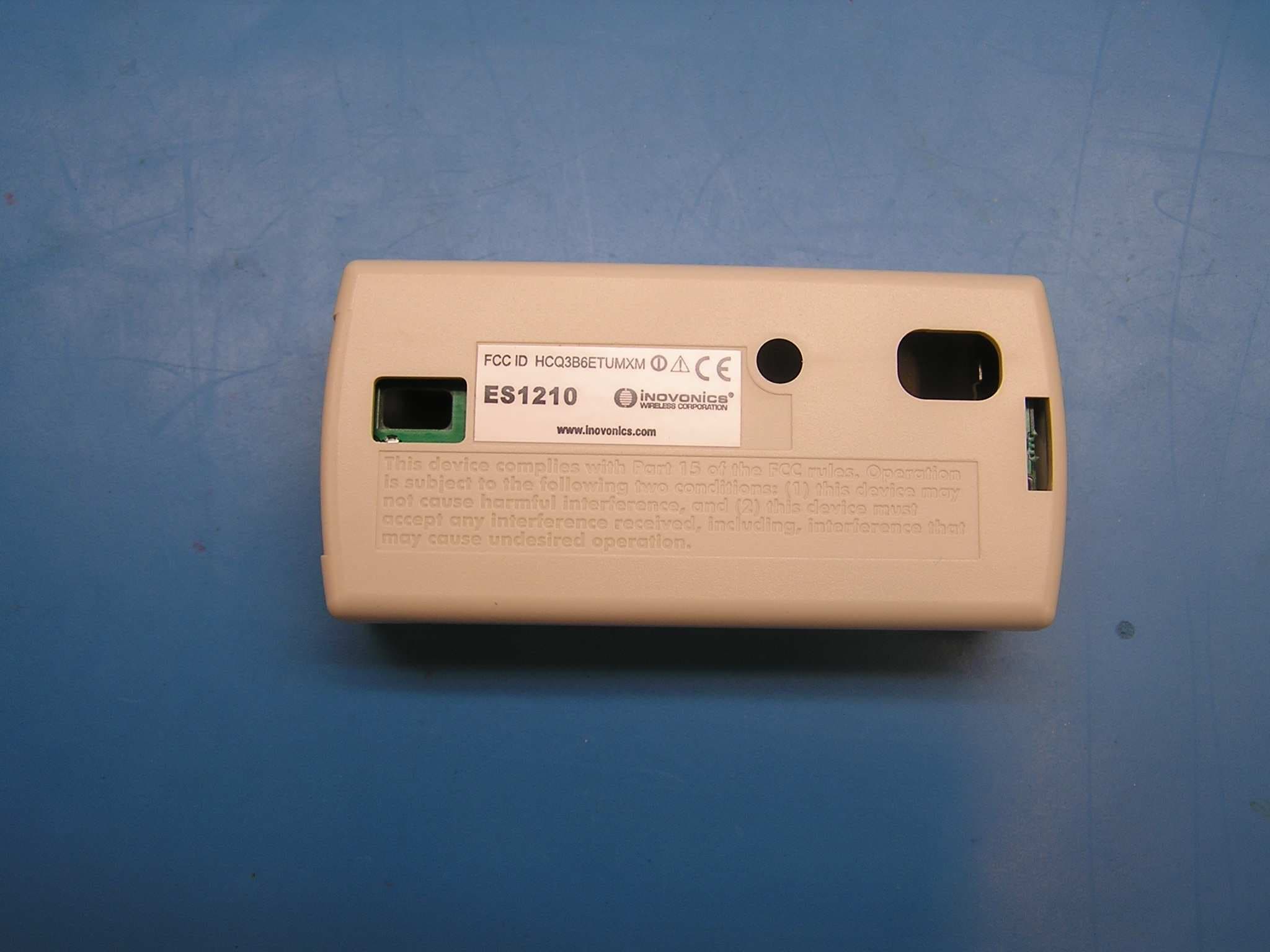
Click to zoom
Application Details
- Equipment Class
- DSS - Part 15 Spread Spectrum Transmitter
- Date of Grant
- May 10, 2004
- Application Purpose
- Original Equipment
- Date of Application
- Dec 07, 2003
- Equipment Note
- Universal Transmitter
- Frequency Range
- 902.40000000 - 927.60000000
- Country
- United States
Documents & Files
Document Text
Text extracted from the exhibit documents filed with the FCC. Open a document above to read the original.
Users Manual
Figure 3 EchoStream™ Select ES1210 Universal Transmitter Installation and Operation Manual - 03902A IMPORTANT NOTE Unless specifically noted, Inovonics Wireless products are intended for indoor use. This transmitter is intended for use with indoor secu- rity systems. Use in outdoor applications may impair performance. MOUNTING(see Figure 1) 1.Mount the bracket on the wall with the screws provided. 2.Clip the transmitter onto the bracket. Hook the bottom catch first, then press the top into place. 3.The housing may be secured with a third mounting screw, located beneath the battery. Accessing this screw on an active transmitter requires opening the housing and removing the battery, causing a tamper condition (if monitored). 4.To dismount the ES1210, pull the transmitter housing carefully out of the mounting bracket from the top. REGISTRATION When prompted by the receiver to "Reset Transmitter", press the Reset button. Each transmitter must be registered in order to be monitored and supervised. After registration, always test the trans- mitter. COMPONENTS(see figure 3) The N/O-N/C JUMPER selects Normally Open or Normally Closed state of the contact circuit, which is wired to the INPUT TERMINAL. The RESET BUTTON re-initialises the transmitter and sends a registration message to the receiver. The FREQUENCY BAND SELECTOR sets trans- mission frequencies per regulatory statutes. CHANGING THE BATTERY 1.Carefully remove old battery. 2.Install new battery. 3.IMPORTANT:Press reset button to re-initialise the transmitter. This product has a battery inside; it should be discarded in accordance to the local laws and practices in the area of use. Inovonics Wireless does not take responsibility for batteries that are not discarded in this manner. A. Optional Mounting HoleE. N/O - N/C Jumper (see step 3)F. Input Terminal B. Mounting HolesG. Reset Button C. External ContactH. Frequency Band Selector D. Tamper Button and Spring SPECIFICATIONS External contacts:N/O or N/C Typical battery life:3-5 years Battery type (BAT604):Panasonic CR123A or equivalent Operating environment:0 to 60°C (32 to 140°F), non- condensing RF frequency range:Selectable: see Figure 3 NOTE: Specifications and data are subject to change without notice. I email: [email protected] iwww.inovonicswireless.com 03902A ©2002 Inovonics Wireless Corporation Figure 1 Figure 2 3 m (10 ft) C EchoStream™ Select ES1210 Emetteur Universel de Taille Réduite Manuel d'installation et d'opération - 03902A NOTE IMPORTANTE À moins qu'indiqué de manière spécifique, les produits Inovonics Wireless sont prévus pour une utilisation interne. Cet emetteur devra être utilisé avec des sys- tèmes de sécurité internes. Son utilisation dans des applications externes risque d’affecter ses performances. MONTAGE(voir figure 1) 1. Montez le support sur le mur à l'aide des vis fournies. Les têtes des vis doivent être affleurantes ou légèrement enfoncées. 2. Attachez l’emetteur sur le support à l'aide d'une pince. Positionner le loquet inférieur d'abord, puis mettez le loquet supérieur en place en appuyant sur lui. 3. Le boîtier pourra être fixé à l'aide d'une troisième vis de montage, placée au- dessous de la pile. L'accès à cette vis sur un emetteur actif requiert l'ouverture du boîtier et le retrait de la pile, ce qui cause une condition de tentative de sabo- tage (si sous contole). 4. Pour démonter le ES1210W, tirez doucement sur le boîtier d’emetteur pour l'ex- traire du support de montage à partir du haut. ENREGISTREMENT Les emetteurs doivent être enregistrés auprès du récepteur système afin de pou- voir être contrôlés et supervisés. Chaque emetteur possède un numéro d'identification unique programmé en usine. Consultez les instructions d'installation du récepteur. Pour enregistrer un emetteur : lorsque le récepteur demande de réinitialiser l’emetteur (" Reset Transmitter "), appuyez sur le bouton Reset. Suivez les instructions afin de tester l’emetteur. COMPOSANTS(voir figure 3) La CONNEXION N/O-N/C sélectionne l'état du circuit de contact - Contact N/O (ouvert au repos) ou N/C (fermer au repos), qui est câblé au terminal d'entrée (INPUT TERMINAL). Le bouton de réinitialisation (RESET BUTTON) réinitialise l’emetteur et envoie un message d'enregistrement au récepteur. CHANGEMENT DE LA PILE 1. Retirez l’ancienne pile avec précaution. 2. Installez la nouvelle pile. 3. IMPORTANT:Appuyez sur le bouton “ reset “ pour réinitialiser l’emetteur. Ce produit contient une pile ; celle-ci devra être détruite conformément aux lois locales et aux pratiques de la région d'utilisation. Inovonics Wireless décline toute responsabilité pour les piles qui n'auront pas été détruites de manière adéquate. A. Trou de montage optionnel (voir étape 3) E. Connexion N/O - N/C B. Trous de montage F. Borne d'entrée C. Contact externe G. Bouton de réinitialisation D. Bouton anti-sabotage et ressort H. Sélecteur de bande de fréquence CARACTÉRISTIQUES Contacts externes :N/O ou N/C Durée de vie de la pile : 3-5 ans Type de pile (BAT604):Panasonic CR123A ou équivalent Temperature de functionnement : 0 à 60°C (32 à 140°F), non-condensé Gamme de fréquences RF :(voir figure 3) N.B. : Les caractéristiques et les données sont susceptibles d'être modifiées sans préavis. I EchoStream™ Select ES1210 Trasmettitore Universale di Piccole Dimensioni, Manuale per il montaggio e il funzionamento - 03902A NOTE IMPORTANTI A meno che non sia specificato diversamente, i prodotti Inovonics Wireless sono solo per uso al chiuso. Il presente trasmettitore è destinato all'uso con sistemi di allarme al chiuso. Utilizzare il prodotto per applicazioni all'aperto significa compro- metterne le prestazioni. MONTAGGIO(vedi fig. 1) 1. Montare la staffa sulla parete avvalendosi delle viti appartenenti alla dotazione. Le teste delle viti devono risultare a raso o leggermente incastrate. 2. Mediante la clip, fissare il trasmettitore alla staffa. Agganciare dapprima l'arresto inferiore, quindi premere la parte superiore, collocando…
Text truncated - open the document above for the full version.
Cover Letter(s)
December 4, 2003 Federal Communications Commission Authorization and Standards Division 7435 Oakland Mills Road Columbia, MD 21046 Subject: Request for Confidentiality for FCC ID# HCQ3B6ETUMXM Gentlemen: The following reports are marked confidential, and should be maintained in the non- public file. This confidentiality is necessary to protect proprietary information contained within these sections of the application for Certification. 1) Operational Description 2) Schematics 3) Block Diagram Thanks for your help. Sincerely, Donald J. Hume President
Cover Letter(s)
April 5, 2004 Applicant: Inovonics Wireless Corp. FCC ID: HCQ3B6ETUMXM Correspondence Reference Number: 26334 731 Confirmation Number: EA718484 Re: Action Items regarding Grant approval 1) Please update the user manual to include installation/RF safety instructions consistent with the 20 cm distance given in the MPE analysis. Rather than change the user manual, the device is shown to meet the requirements of 47CFR2.1093, at maximum duty cycle. The maximum duty cycle of the device is 0.36%, which consists of an alarm message, a restore message, and a supervisory message in a 3-minute window. 33 packets are used to transmit these messages. The time-averaged RF transmit power is then, mW mspacket mspackets mW183.0 1060 min120 min3 33 50 3 = ¥ ¥¥¥ Worst case, if all of the transmitted power were absorbed in a 1-gram sample of tissue, the power density is 0.133 mW/gram and is well below the 1.6 mW/gram limit found in 47CFR2.1093. 2) Please clarify maximum power. The MPE analysis suggests maximum power is 250 mW while Form 731 states 50 mW. Please explain and correct as appropriate. The maximum RF power level of the device is 50 mW. The value of 250 mW was used in the MPE analysis to demonstrate that even at the worst-case power limit allowed by 47CFR15.247, the device is compliant with 47CFR2.1091. 3) Please confirm that the MPE analysis was performed at the maximum duty cycle of the device. Maximum duty cycle will go on the grant. The maximum duty cycle of the device is %36.00036.0 1060 min120 min3 33 3 == ¥ ¥¥ mspacket mspackets
External Photos
FCC ID: HCQ3B6ETUMXM ES1210 4. External Photos: Topside view. Bottom side view
ID Label/Location Info
CONFIDENTIAL DOCUMENT ES1210 Label 03930A CONFIDENTIAL DOCUMENTATION The information contained in this document is confidential to and the sole property of Inovonics Corporation. Receipt of this information requires the existence and full acceptance of the terms and conditions of a Non Disclosure Agreement signed by the Inovonics Corporation and the Recipient. This documentation is not to be reproduced or redistributed except as provided in the Non Disclosure Agreement. MATERIAL:.002" THICK WHITE MYLAR WITH .001" MATTE LAMINATION (FOR PROTECTION FROM INK SMEARING) AND PERMANENT ADHESIVE APPLIED TO THE BACKSIDE ARTWORK:SUPPLIED BY INOVONICS TEXT: BLACK LABEL SIZE: 1.220" X .0.455" (SHOWN TO 3 TIMES SCALE), SHARP CORNERS AND NO BORDER PACKAGING AND LABEL ORIENTATION:LABELS TO BE SUPPLIED ON TOP SIDE OF ROLL STOCK WITH TEXT READABLE AS VIEWED FROM BOTTOM (SHORT) EDGE OF ROLL Rev. Level DescriptionDate AInitial Release6/25/2003 Confidential to InovonicsES121003930A_qxd FCC ID HCQ3B6ETUMXM JJ II ES1210 www.inovonics.com
Internal Photos
FCC ID: HCQ3B6ETUMXM ES1210 6. Internal photos: PCB Topside PCB bottomside
Parts List/Tune Up Info
FCC ID: HCQ3B6ETUMXM ES1210 8. Parts List/Tune Up Info: This exhibit does not apply to this device.
RF Exposure Info
FCC ID: HCQ3B6ETUMXM ES1210 9. RF Exposure Information: Calculation for compliance with MPE requirements (47CFR2.1091) is done using a worst-case transmitter power of 250 mW, assumption of a unity gain antenna, and an exposure limit of 0.6 mW/cm 2 (f/1500 mW/cm 2 at 20 cm per 47CFR1.1310) for general applications. This device is not carried or worn by the end user. It has an extremely low duty cycle and a low rate of transmission that dramatically reduces the average power level that could pose an exposure hazard. The transmitter is typically activated by the opening or closing of a door or window. In addition to these change-of-state transmissions, the transmitter is configured to transmit a supervisory message once every 3 minutes. The averaging interval specified in Table 1(B) of 47CFR1.1310 is 30 minutes. For the purposes of this calculation, it is assumed that ten supervisory and five change-of- state messages will be sent in the 30-minute interval. Each supervisory message consists of 3 redundant packets, and each change of state message contains 21 packets, for a total of 135 packets in the 30-minute interval. A packet is typically 20 ms in length. The worst-case power density at a distance of 20 cm is then, 223 6.74 )20(4 1 1060 min120 min30 135 250 cm nW cmms packet mspackets mW=¥ ¥ ¥¥¥ p This is well below the 0.6 mW/cm 2 limit.
Test Report
FCC ID: HCQ3B6ETUMXM ES1210 11. Test Report The test report containing intentional/unintentional emissions data is attached as “BC300339-1c_ES121x_.pdf”. International Approvals Laboratories generated this report. Additional data demonstrating compliance with 47CFR15.247 follows. For the following plots, the antenna was replaced by a coaxial connection to a an HP8594E spectrum analyzer. Plot 1 is a spectrum plot showing a minimum channel separation of 800 kHz. Compliance with section 15.247(a)(1) is demonstrated by capturing several transmissions over a small portion of the 902-928 MHz ISM band. Plot 1: Demonstration of channel spacing requirement. FCC ID: HCQ3B6ETUMXM ES1210 Plot 2 demonstrates compliance with 15.247(a)(1)(i) — Number of hopping channels. This is a stored display of many sequential transmissions to show the overall band occupied by the transmitter. Plot 2: Demonstration of 25 hopping channels. Plots shows the 20 dB bandwidth of a single channel to demonstrate compliance with 15.247(a)(1)(i). The 20 dB occupied bandwidth is 250 kHz. Plot 3: Demonstration of occupied bandwidth.
Test Report
EMC EMISSIONS - TEST REPORT (In-Part) Test Report No. BC300339-1c Issue Date: Thu 11/Sep/2003 Model / Serial No. ES1247, ES121x, ES1242, ES1262 / SN: 1 Product Type Glass break detector Client Inovonics Wireless Manufacturer Inovonics Wireless License holder Inovonics Wireless 315 CTC Boulevard Address Louisville, CO 80027 Test Criteria Applied FCC Part 15.247 Test Result PASS Test Project Number References BC300339-1c Total Pages Including Appendices: 23 FCC CFR47 Part 15: Radio Frequency Devices Reviewed By : Todd Seeley Approved By : Robert Cresswell INTERNATIONAL APPROVALS LABORATORIES (IAL) reports apply only to the specific samples tested under stated test conditions. It is the manufacturer's responsibility to assure that additional production units of this model are manufactured with identical electrical and mechanical components. IAL have no liability for any deductions, inferences or generalizations drawn by the client or others from IAL issued reports. This report is the confidential property of the client. As a mutual protection to our clients, the public and ourselves, extracts from the test report shall not be reproduced except in full without our written approval of IAL. This report shall not be used by the client to claim product endorsement by NVLAP (No. 200624- 0) or any agency of the US government. International Approval Laboratories and its professional staff hold government and professional organization certifications and are members of IEEE, NVLAP, and VCCI. Project File: BC300339 -1c_ES1247 Page 2 of 23 International Approvals Laboratories, LLC 5541 Central Avenue, Suite 110 Boulder, Colorado 80301 Voice: 303 786 7999 Fax: 303 449 6160 Rev.No 1 D I R E C T O R Y Documentation Page(s) Test report 1 - 23 Directory 2 Test Regulations 3 General Remarks 3 Test-setup Photographs 4 - 7 Appendix A Test Data Sheets and Test Equipment Used 8 - 17 Appendix B Test Plan/Constructional Data Form 18 - 18 Appendix C Measurement Protocol/Test Procedures 19 - 23 STATEMENT OF MEASUREMENT UNCERTAINTY The data and results referenced in this document are true and accurate. The measurement uncertainty for Conducted Emissions in the frequency range of 150kHz – 30MHz is calculated to be ±2.30dB and for Radiated Emissions is calculated to be ±3.60dB in the frequency range of 30MHz – 200MHz and ±3.38dB in the frequency range of 200MHz – 1000MHz. EUT Received Date: 2-Sep-2003 Testing Start Date: 2-Sep-2003 Testing End Date: 11-Sep-2003 Project File: BC300339 -1c_ES1247 Page 3 of 23 International Approvals Laboratories, LLC 5541 Central Avenue, Suite 110 Boulder, Colorado 80301 Voice: 303 786 7999 Fax: 303 449 6160 Rev.No 1 The tests were performed according to following regulations : 1. FCC CFR47 Part 15.209 2. FCC CFR47 Part 15.205 3. FCC CFR47 Part 15.247 (a) & (c) Emission Test Results: Conducted Emissions, Powerline - 15.207 (not applicable) Test Result Minimum limit margin dB at MHz Maximum limit exceeding dB at MHz Remarks: Radiated Emissions (Electric Field) - 15.209 - PASS Test Result Minimum limit margin -16.70 dB at 811.66 MHz Maximum limit exceeding dB at MHz Remarks: Radiated Emissions (Electric Field) - 15.247(a) - PASS Test Result Minimum limit margin -21.88 dB at 914.84 MHz Maximum limit exceeding dB at MHz Remarks: Radiated Emissions (Electric Field) - 15.247(c) - PASS Test Result Minimum limit margin -8.88 dB at 2782.78 MHz Maximum limit exceeding dB at MHz Remarks: General Remarks: This Test Report covers the following transmitters: ES121x (door/windows xmitter), ES1242 (smoke detector), ES1247 (glass break), ES1262 (small PIR) for the fact that the RF circuitry and antenna are identical in compone nts, schematic, and layout. The ES1247 (glass break) transmitter was chosen as the worst case configuration for the fact that it has additional leads attached for the glass break sensor within the unit. Modifications required to pass: Test Specification Deviations: Additions to or Exclusions from Project File: BC300339 -1c_ES1247 Page 4 of 23 International Approvals Laboratories, LLC 5541 Central Avenue, Suite 110 Boulder, Colorado 80301 Voice: 303 786 7999 Fax: 303 449 6160 Rev.No 1 Test-setup photo(s): Unintentional Radiated Emissions Project File: BC300339 -1c_ES1247 Page 5 of 23 International Approvals Laboratories, LLC 5541 Central Avenue, Suite 110 Boulder, Colorado 80301 Voice: 303 786 7999 Fax: 303 449 6160 Rev.No 1 Test-setup photo(s): Unintentional Radiated Emissions Project File: BC300339 -1c_ES1247 Page 6 of 23 International Approvals Laboratories, LLC 5541 Central Avenue, Suite 110 Boulder, Colorado 80301 Voice: 303 786 7999 Fax: 303 449 6160 Rev.No 1 Test-setup photo(s): Intentional Radiated Emissions Project File: BC300339 -1c_ES1247 Page 7 of 23 International Approvals Laboratories, LLC 5541 Central Avenue, Suite 110 Boulder, Colorado 80301 Voice: 303 786 7999 Fax: 303 449 6160 Rev.No 1 Test-setup photo(s): Intentional Radiated Emissions Project File: BC300339 -1c_ES1247 Page 8 of 23 International Approvals Laboratories, LLC 5541 Central Avenue, Suite 110 Boulder, Colorado 80301 Voice: 303 786 7999 Fax: 303 449 6160 Rev.No 1 Appendix A Test Data Sheets and Test Equipment Used Unintentional Radiated Emissions Test Report #: BC300339 Run 10 Test Area: Pinewood Site 1 (3m) Temperature: 21.6 °C Test Method: FCC Part 15.209 Test Date: 11-Sep-2003 Relative Humidity: 54 % EUT Model #: ES1223, ES1233, ES1260, ES1247 EUT Power: 3 VDC Air Pressure: 81 kPa EUT Serial #: 1, 1, 1, 1 Page: 1 of 5 Manufacturer: Inovonics Level Key EUT Description: Security Transmitters Pk – Peak Nb – Narrow Band Notes: All four units are being tested simultaneously Qp – QuasiPeak Bb – Broad Band All tranmitters are hopping, normal operation Av - Average FREQ LEVEL CABLE / ANT / PREAMP FINAL POL / HGT / AZ DELTA1 (dB) DELTA2 (dB) (MHz) (dBuV) (dB) (dB\m) (dB) (dBuV/m) (m) (DEG) FCC B (< 1GHz) FCC B (> 1GHz) Log Antenna, Vertical, 200-1,000 MHz 0 degrees No emissions detected 90 degrees No emissions…
Text truncated - open the document above for the full version.
Test Setup Photos
FCC ID: HCQ3B6ETUMXM ES1210 12. Test Setup Photos The test setup photos are contained within the test report of the previous section.
Contact Information
Applicant
Jess Cobb(Manager of Program Mgmt)
Technical Contact
Inovonics Wireless CorporationSteve Dunbar
[email protected]303-209-7174
315 CTC Blvd. · Louisville, Colorado · United States
Non-Technical Contact
Inovonics Wireless CorporationAmy Arguelles
[email protected]303-209-7167
Test Firm
International Approval Laboratories, LLCTodd Seeley
Technical Specifications
| # | Rule Parts | Frequency Range | Power Output | Emission | Tolerance |
|---|---|---|---|---|---|
| 1 | 15C | 902.4 MHz - 927.6 MHz | 50.00 mW | 250KF1D | 1.0000000000 ppm |
Other Applications from Inovonics Wireless Corporation

HCQ-IDTOUCH1
May 13, 2026Inovonics Wired Touchscreen Keypad
Equipment Class
DTS - Digital Transmission System
HCQBWA02
Aug 28, 2024Flush Mount Locator
Equipment Class
DSS - Part 15 Spread Spectrum Transmitter
HCQTBA
Sep 21, 2022TBA Module
Equipment Class
DSS - Part 15 Spread Spectrum Transmitter
HCQPFA01
Jul 14, 2022Fall Detect Transmitter
Equipment Class
DSS - Part 15 Spread Spectrum Transmitter
HCQ3B6BRGSA
Sep 22, 2020Bluetooth to EchoStream Bridge
Equipment Class
DTS - Digital Transmission System