HCQ3B6ETVCSMContainer Sensor
Inovonics Wireless Corporation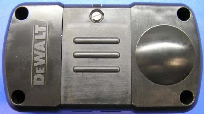
Click to zoom
Application Details
- Equipment Class
- DSS - Part 15 Spread Spectrum Transmitter
- Date of Grant
- Jan 05, 2005
- Application Purpose
- Original Equipment
- Date of Application
- Nov 14, 2004
- Equipment Note
- Container Sensor
- Frequency Range
- 902.40000000 - 927.60000000
- Country
- United States
Documents & Files
Document Text
Text extracted from the exhibit documents filed with the FCC. Open a document above to read the original.
Users Manual
DS350 Container Sensor WARNING: Read and understand all instructions and warnings for this product.In addition, read and follow all instructions and warnings provided with the DS100 JobSite Security Portable Alarm System. CAUTION: DANGER OF EXPLOSION, INJURY, OR FIRE. Carefully follow all instructions and warnings on the battery label and package. • Never use a damaged or worn out battery. • Discharged batteries should be replaced only with type CR-123 3.0 Volt Lithium batteries. • Do not use re-chargeable batteries or attempt to charge batteries. • Carefully remove the old, discharged battery. • Do not attempt to open. • Do not peel the label from the battery. • Never dispose of a battery in a fire. • Dispose of used batteries in accordance with local regulations. • Recycle batteries. • Always insert batteries correctly with regard to polarity (+ and -) marked on the battery and the equipment. • When installing the battery, do not use excessive force. If the bat- tery does not fit, check to make sure that it matches the polarity markings. • Never expose the battery terminals to any other metal object. This can short circuit the battery. • Avoid exposure to temperature extremes. • When not in use, store the battery in a cool, dark, dry place. • Keep batteries out of reach of children. • This product is designed for indoor/outdoor use. FCC REGULATORY STATEMENT(FCC: HCQ3B6ETVCSM) • This device complies with Part 15 of the FCC rules. Operation is subject to the following two conditions: (1) This device may not cause harmful interference, and (2) the device must accept any interference received, including interference that may cause unde- sired operation. INDUSTRY CANADA(IC: 2309A-ETVCSM) •NOTICE:This equipment meets the applicable Industry Canada Terminal Equipment Technical Specifications. This is confirmed by the registration number. The abbreviation, IC, before the reg- istration number signifies that registration was performed based on a Declaration of Conformity indicating that Industry Canada technical specifications were met. It does not imply that Industry Canada approved the equipment. Components (Fig. 1) A. SounderD. Sensitivity Adjustment B. TampersE. Battery C. Reset ButtonF. Captive Screw Product Function The DS350 Container Sensor is used for monitoring remote metal containers by measuring vibration. Once activated, this device will work exclusively with the assigned DS100 JobSite Security Portable Alarm System. 1. The DS350 features 900 MHz spread spectrum communication with the Base Unit allowing for a range of up to 2000' (610 m). 2. The Container Sensor includes user adjustable controls which allow for sensitivity adjustments to avoid false alarms. 3. A 80db sounder is used for testing sensitivity. 4. The durable housing was designed for mounting the DS350 on the outside of containers and tough enough to withstand outdoor conditions. 5. Temporary mounting capabilities with the use of magnets or permanent mounting by mounting with bolts. 6. Captive screw used to keep the front cover closed. 7. The DS350 Container Sensor uses a CR-123 3.0V Lithium battery for long life. 8. The DS350 features an inside tamper that notifies the system when the sensor cover is removed. 9. The DS350 also features an outside tamper that notifies the sys- tem when the sensor has been removed from the container to which it was affixed. 10. The reset button allows the Container Sensor to be registered to any D EWALT JobSite Security system with easy set up. NOTE:Metal objects blocking radio frequency (RF) transmission can affect the range of the sensor. Prevention of False Alarms The majority of alarms that occur are false. These situations happen every day due to user error, incorrect installation or improper mainte- nance of the system. False alarms will limit the responsiveness to the system, and become a general inconvenience. As the number of false alarms increases, authorities have become less apt to respond to alarm systems due to this problem. Many of these situations can be avoided by following some very simple practices. • Ensure all users are properly trained on the operation of the system. • Always turn off the system with the Key Chain Remote Control before entering protected area. • Lock all protected doors, windows or any other asset attached to a sensor. • Check that motion detectors are not obstructed. Do not allow sources of heat or sound in range of the motion or vibration sensors. A B FIG. 1 FIG. 2 SITELOCK LLC, 626 Hanover Pike, Hampstead, MD 21074(AUG04) Form No. XXXXXX-XXDS350 Copyright © 2004 D EWALT CAUTION: POTENTIAL EQUIPMENT MALFUNCTION OR FAILURE. Do not touch the electronic components inside the device, except the reset button and battery. CAUTION: POTENTIAL EQUIPMENT MALFUNCTION OR FAILURE. Metal objects blocking radio frequency (RF) transmission can affect the range of the sensor. Place Container Sensor on the OUTSIDEof a metal container to ensure transmission of RF signal. E C D F B FIG. 3 G G SUGGESTED LOCATIONS • Check that premises are cleared and assets secured before setting the system. • Turn off all noise sources – radios, compressors, generators, heavy equipment, etc. • Know how to cancel an alarm or turn off the system before activating. • If a false alarm is tripped notify customer service immediately. • Test the system on a monthly basis to ensure proper functioning • Check cellular signal, power supply, and that sensors are secured on a daily basis. Recommended Locations • Recommended for use on steel containers, large tool boxes, and tool storage boxes. • Place on the OUTSIDEof a metal container to ensure transmission of RF signal. Installing & Changing Battery The DS350 Container Sensor requires a non-rechargeable CR-123 3.0 Volt Lithium battery. TO INSTALL A BATTERY 1. Using a Phillips screwdriver, loosen the captive screw (F). 2. Flip open the latch. 3. Install the battery using the polarity (+ and -) markings on the battery and equipment. Do not use …
Text truncated - open the document above for the full version.
Cover Letter(s)
November 12, 2004 Federal Communications Commission Authorization and Standards Division 7435 Oakland Mills Road Columbia, MD 21046 Subject: Request for Confidentiality for FCC ID# HCQ3B6ETVCSM Gentlemen: The following reports are marked confidential, and should be maintained in the non- public file. This confidentiality is necessary to protect proprietary information contained within these sections of the application for Certification. 1) Operational Description 2) Schematics 3) Block Diagram Thanks for your help. Sincerely, Donald J. Hume President
External Photos
FCC ID: HCQ3B6ETVCSM DS350 4. External Photos: Topside view. Bottom side view FCC Label
ID Label/Location Info
DOC NO: 626826-PDF1 REV: 0 VERSION: 1 TITLE: LABEL, N/P DS350 EC: EC0223527 PND
Internal Photos
FCC ID: HCQ3B6ETVCSM DS350 6. Internal photos: Cover Removed PCB topside PCB bottom side Integrated Antenna RF Shielding Shown without shield can.
RF Exposure Info
FCC ID: HCQ3B6ETVCSM DS350 9. RF Exposure Information: The device is compliant with both MPE requirements (47CFR2.1091) as well as SAR requirements (47CFR2.1093). Calculation for compliance with MPE requirements (47CFR2.1091) is done using a worst-case transmitter power of 50 mW, assumption of a unity gain antenna, and an exposure limit of 0.6 mW/cm 2 (f/1500 mW/cm 2 at 20 cm per 47CFR1.1310) for general applications. This device is not carried or worn by the user. It has an extremely low duty cycle and a low rate of transmission that dramatically reduces the average power level that could pose an exposure hazard. The Container sensor initiates an alarm transmission upon sensing vibration. The DS350 is configured to transmit a supervisory message once every 3 minutes. The averaging interval specified in Table 1(B) of 47CFR1.1310 is 30 minutes. For the purposes of this calculation, it is assumed that ten supervisory and 20 alarm messages will be sent in the 30-minute interval. Each supervisory message contains 3 packets, and each alarm message contains 21 packets, for a total of 450 packets in the 30-minute interval. A packet is 20 ms in length. The worst-case average power density at a distance of 20 cm is then, 223 7.49 )20(4 1 1060 min120 min30 450 50 cm nW cmms packet mspackets mW=× × ××× π This is well below the 0.6 mW/cm 2 MPE limit. Calculation for compliance with SAR requirements (47CFR2.1093) is done using a worst-case transmitter power of 50 mW time-averaged by the duty cycle of the transmitter, and the assumption that all RF energy could be absorbed in 1 gram of tissue. The peak exposure limit is 1.6 mW/g (equivalent to 1.6 W/kg per 47CFR2.1093) in any 1 gram of tissue for General Population/Uncontrolled applications. In any 3-minute interval, worst-case the device may transmit up to 2 alarm messages and a supervision message for a total of 45 packets. The maximum duty cycle of the device is, %5.0005.0 1060 min120 min3 45 3 == × ×× ms packet mspackets FCC ID: HCQ3B6ETVCSM DS350 The time-averaged RF transmitted power is then, mWW25.0005.005.0=× If all of the transmitted power were absorbed in a 1-gram sample of tissue, the resulting power density is 0.25 mW/gram and is well below the 1.6 mW/gram limit.
Test Report
EMC EMISSIONS - TEST REPORT (In-Part) Test Report No. BC400278b-1 Issue Date: July 1, 2004 Model / Serial No. DS350 / proto #1 Product Type Intentional Transmitter Client Inovonics Wireless Corp. Manufacturer Inovonics Wireless Corp. License holder Inovonics Wireless Corp. 315 CTC Blvd Address Louisville, CO 80027 Test Criteria Applied FCC CFR47 Part 15.247 Test Result PASS Test Project Number References BC400278-1 Total Pages Including Appendices: 34 Title 47 CFR 15: RADIO FREQUENCY DEVICES Reviewed By : Approved By : INTERNATIONAL APPROVALS LABORATORIES (IAL) reports apply only to the specific samples tested under stated test conditions. It is the manufacturer's responsibility to assure that additional production units of this model are manufactured with identical electrical and mechanical components. IAL have no liability for any deductions, inferences or generalizations drawn by the client or others from IAL issued reports. This report is the confidential property of the client. As a mutual protection to our clients, the public and ourselves, extracts from the test report shall not be reproduced except in full without our written approval of IAL. This report shall not be used by the client to claim product endorsement by NVLAP (No. 200624- 0) or any agency of the US government. International Approval Laboratories and its professional staff hold government and professional organization certifications and are members of IEEE, NVLAP, and VCCI. Project File: BC400278 Page 2 of 34 International Approvals Laboratories, LLC 5541 Central Avenue, Suite 110 Boulder, Colorado 80301 Voice: 303 786 7999 Fax: 303 449 6160 Rev.No 1 D I R E C T O R Y Documentation Page(s) Test report 1 - 34 Directory 2 Test Regulations 3 General Remarks 4-5 Test-setup Photographs 6 - 10 Appendix A Test Data Sheets and Test Equipment Used 11 - 26 Appendix B Test Plan/Constructional Data Form 27 - 29 Appendix C Measurement Protocol/Test Procedures 30 - 34 STATEMENT OF MEASUREMENT UNCERTAINTY The data and results referenced in this document are true and accurate. The measurement uncertainty for Conducted Emissions in the frequency range of 150kHz – 30MHz is calculated to be ±2.30dB and for Radiated Emissions is calculated to be ±3.60dB in the frequency range of 30MHz – 200MHz and ±3.38dB in the frequency range of 200MHz – 1000MHz. EUT Received Date: 3-June-2004 Testing Start Date: 3-June-2004 Testing End Date: 6-July-2004 Project File: BC400278 Page 3 of 34 International Approvals Laboratories, LLC 5541 Central Avenue, Suite 110 Boulder, Colorado 80301 Voice: 303 786 7999 Fax: 303 449 6160 Rev.No 1 The tests were performed according to following regulations : 1. FCC CFR47 Part 15.205 2. FCC CFR47 Part 15.207 3. FCC CFR47 Part 15.209 4. FCC CFR47 Part 15.247 5. ICES-003 Emission Test Results: Conducted Emissions, Powerline (15.207) - Not Applicable Test Result Minimum limit margin NA dB at NA MHz Maximum limit exceeding dB at MHz Remarks: Battery operated device. Radiated Emissions (15.209) - PASS Test Result Minimum limit margin -13.5 dB at 204.18 MHz Maximum limit exceeding dB at MHz Remarks: Radiated Emissions (15.205)/(15.247) (c) - PASS Test Result Minimum limit margin -0.18 dB at 5414.11 MHz Maximum limit exceeding dB at MHz Remarks: Peak Output Power (15.247) (b)(1) - PASS Test Result Minimum limit margin -22.48 dB at 914.73 MHz Maximum limit exceeding dB at MHz Remarks: Project File: BC400278 Page 4 of 34 International Approvals Laboratories, LLC 5541 Central Avenue, Suite 110 Boulder, Colorado 80301 Voice: 303 786 7999 Fax: 303 449 6160 Rev.No 1 GENERAL REMARKS: The following remarks are to be considered as “where applicable“ and are taken into account while completing any FCC/IC/ETSI radio tests at International Approvals Laboratories, LLC. Testing was performed in 3 different orthogonal axis to determine the worst case emissions from the device. The worst case emissions measurements are shown in this report. FCC CFR47 Part 15.31: Measurement Standards: In any case where the device is powered off a battery, a fresh battery was used during test. In cases where the device is powered off an AC supply, voltage was varied per Part 15.31 to find worst case emissions. FCC CFR47 Part 15.35: Measurement Detector Functions and Bandwidths: FCC Part 15.35 was utilized when performing the measurements within this report. In any case where the device is powered off a battery, a fresh battery was used during test. In cases where the device is powered off an AC supply, voltage was verified per Part 15.31 to find worst case emissions. The actual test distance for the FCC Part 15.209 testing was conducted at 10m for the fact that the device was being tested to EN55022 Class B from 30 MHz to 1000 MHz (meets/exceeds the FCC Part 15.209 & 109B limits) The data is automatically extrapolated back to the FCC 3m limits and measurements are corrected to better show the compliance to FCC requirements and reduce confusion. A correction factor of 10.54dB is used in cases of 30MHz and up for a difference between 10m and 3m measurement distances. All measurements that are lesser than 30MHz where applicable are accompanied with the fall of measurements and calculations to support the interpolation. Modifications required to pass: Test Specification Deviations: Additions to or Exclusions from This test report is in-part, International Approvals Laboratories, LLC was asked to test only the field strength of the fundamental and harmonics as well as the unintentional radiated and conducted emissions when applicable. Project File: BC400278 Page 5 of 34 International Approvals Laboratories, LLC 5541 Central Avenue, Suite 110 Boulder, Colorado 80301 Voice: 303 786 7999 Fax: 303 449 6160 Rev.No 1 Required Information In Accordance to FCC CFR 47 Part 2.1033: Exhibits Including (where applicable): 1. Users Manual 2. Operation Description 3. Block Diagram 4. Report of Measurement 5. External & Internal Photographs 6. Schematic 7. Parts List 8. Tuning P…
Text truncated - open the document above for the full version.
Test Setup Photos
FCC ID: HCQ3B6ETVCSM DS350 12. Test Setup Photos The test setup photos are contained within the test report of the previous section.
Contact Information
Applicant
Jess Cobb(Manager of Program Mgmt)
Technical Contact
Inovonics Wireless Corp.Hans Balderrama
[email protected]303-209-7202
315 CTC Blvd. · Louisville, Colorado · United States
Non-Technical Contact
Inovonics Wireless Corp.Amy Arguelles
[email protected]303-209-7167
Test Firm
International Approval Laboratories, LLCTodd Seeley
Technical Specifications
| # | Rule Parts | Frequency Range | Power Output |
|---|---|---|---|
| 1 | 15C | 902.4 MHz - 927.6 MHz | 50.00 mW |
Other Applications from Inovonics Wireless Corporation

HCQ-IDTOUCH1
May 13, 2026Inovonics Wired Touchscreen Keypad
Equipment Class
DTS - Digital Transmission System
HCQBWA02
Aug 28, 2024Flush Mount Locator
Equipment Class
DSS - Part 15 Spread Spectrum Transmitter
HCQTBA
Sep 21, 2022TBA Module
Equipment Class
DSS - Part 15 Spread Spectrum Transmitter
HCQPFA01
Jul 14, 2022Fall Detect Transmitter
Equipment Class
DSS - Part 15 Spread Spectrum Transmitter
HCQ3B6BRGSA
Sep 22, 2020Bluetooth to EchoStream Bridge
Equipment Class
DTS - Digital Transmission System