HCQ3B6IX9NCUArea Control Gateway
Inovonics Wireless Corporation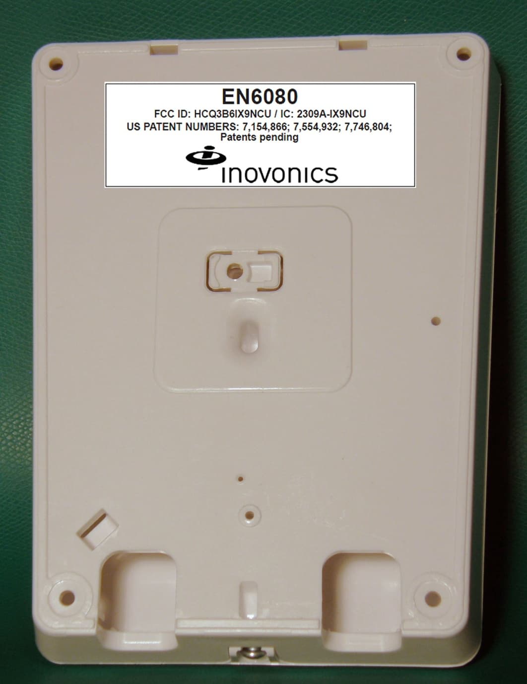
Click to zoom
Application Details
- Equipment Class
- DSS - Part 15 Spread Spectrum Transmitter
- Date of Grant
- Jun 07, 2012
- Application Purpose
- Original Equipment
- Date of Application
- Jun 06, 2012
- Equipment Note
- Area Control Gateway
- Frequency Range
- 902.40000000 - 927.60000000
- Country
- United States
Documents & Files
Document Text
Text extracted from the exhibit documents filed with the FCC. Open a document above to read the original.
Users Manual
5.8.12 06369B © Inovonics, 2012 - www.inovonics.com EN6080 Area Control Gateway Installation Instructions 1 Overview The Inovonics EN6080 area control gateway bridges the proprietary Inovonics commercial mesh network to a standard TCP-IP over Ethernet LAN. Featuring a PSIA-compliant set of RESTful web services, the EN6080 area control gateway is designed to ensure interoperability with other IP- enabled devices across the security industry. 1.1 Installing an Inovonics Security System An EchoStream survey kit should be used to establish an EchoStream system. The EchoStream survey kit measures the signal strength of high- power repeater and sensor messages to help optimize your EchoStream system. Figure 1 Sample EchoStream system The EchoStream survey kit provides you with two signal strength measurements: signal level and signal margin. Signal level The signal level is the measurement of the overall decibel level of the message. Signal margin The signal margin is the measurement of the decibel level of the message, minus the decibel level of any interfering signals. Inovonics equipment should be placed within a facility such that all end-devices produce signal margin readings of at least 4 decibels. Both the signal level and signal margin are measured in decibels. Because signal strength and signal margin are measured on a logarithmic scale, the difference between a decibel level of 3 (Weak) and a decibel level of 4 (Good) is a much larger difference than it would be on a linear scale. Note: For more information about the EchoStream survey kit, see the EN/ EE7016SK EchoStream® Survey Kit Installation and Operation Manual. 1.2 Inovonics Wireless Contact Information If you have any problems with this procedure, contact Inovonics Wireless technical services: • E-mail: [email protected] • Phone: (800) 782-2709; (303) 939-9336 1.3 EN6080 Area Control Gateway Front Panel Figure 2 EN6080 front panel Operation LEDs Power LED: Green indicates the presence of line power or power over Ethernet. Radio LED: Green indicates that the device is decoding messages from the wireless network. LAN LED: Green indicates Ethernet link. 1.4 EN6080 Area Control Gateway Internal Components Figure 3 IBEX internal components APower LEDBRadio LEDCLAN LED AWall mount holesBHousing cover release screw CPower connections DRJ45 Ethernet jackEOperation LEDsFDiagnostic LEDs GFrequency band selection pins HReset buttonICabling port JWall tamper mounting hole KHousing tamper switch LCabling tie loop MBattery holder A B C A A A A B C D G E F H I I J K L M 5.8.12 06369B © Inovonics, 2012 - www.inovonics.com 2 Diagnostic LEDs Static LED: Yellow indicates the EN6080 is using a static IP address; green indicates the EN6080 is using a dynamic IP address obtained from the network; no illumination indicates the EN6080 has been configured to use a dynamic IP address but has not obtained one from the network, or there is no Ethernet connection. Alarm LED: Red indicates an alarm in the wireless network. Fault LED: Yellow indicates a tamper, low battery, or repeater line power loss fault in the wireless network. 1.5 What’s In The Carton • One 14VAC/120AC transformer • One CR1220 backup battery • Five drywall anchors • Five mounting screws • One frequency band selection jumper 2 Installation and Startup 2.1 Installation Notes • These products are designed to be maintained by professional security technicians • Products are tested for indoor use • All products should be manually tested weekly 2.2 Connect Power Cabling And Install Backup Battery Note: The EN6080 area control gateway is Power over Ethernet capable on any network supporting the IEEE 802.3af-2003 PoE or IEEE 802.3at- 2009 PoE+ standard. Power over Ethernet will only function when line power is not present. To use line power, you will need to connect a power source to the EN6080 area control gateway: 1.Use a Phillips screwdriver to loosen the housing cover release screw (Figure 3). 2.Lift the cover off the hinges on the top of the housing. 3.Connect power cabling to the Vs and GND connections (Figure 3). 4.Ensuring the polarity corresponds, connect DC power cabling to the + and - connections; AC power does not require specific polarity and can use either connection (Figure 3). • Use 14-22 gauge wire for all cabling and ensure torque on the screw terminals does not exceed seven inch-pounds. 5.Route the power cabling through the cabling ports on the bottom of the housing (Figure 3). 6.Connect the power cabling to your power source. • The power source must be 12-24 VAC or VDC. The power supply must be unswitched, uninterrupted, and regulated. 7.Insert the backup battery in the battery holder (Figure 3). 2.3 Select the Frequency Band EchoStream products are able to use a range of radio frequencies, and must be configured for your geographic area. This product ships with a default frequency range of 902-928 MHz for use in North America. If you are using the product in North America, skip to 2.4, “Connect Ethernet Cabling”; f you are using the product in Australia or New Zealand, you will need to configure the transmitter. 8.Place a selection jumper on the frequency band selection pins appropriate to your geographic area (Figure 3). • Place the jumper on the top two pins, marked NZ, to set the frequency range to 921-928 MHz for New Zealand • Place the jumper on the bottom two pins, marked AUS, to set the frequency range to 915-928 MHz for Australia. 9.Press the reset button to complete configuration (Figure 3). 2.4 Connect Ethernet Cabling The EN6080 area control gateway connects to network components in a wired local area network (LAN) using the RJ45 Ethernet jack. To connect to a LAN: 10.Connect one end of a RJ45 patch cable to the RJ45 Ethernet jack on the EN6080 area control gateway (Figure 3). 11.Route the Ethernet patch cable through the cabling ports on the bottom of the housing (Figure 3). 12.Connect the other end of the RJ45 patch cable to an RJ45 Ethernet jack connected…
Text truncated - open the document above for the full version.
Block Diagram
IBEX IX9-NCU Rev A Block Diagram RTC RF Frontend RF TX/RX Module Micro Processor MSP430F5418 Clock Antenna Diversity MSP430F5418 oard Header TCXO L/UART 30MHz 16MHz 16MHz Synthesizer Daughterbo Expansion H Micro Processor LEDs 16MHz BSL USB/UART/SPI 50MHz 25MHz et D E Micro Processor MK60DN512ZVMD10 Status 64 Mb SPI Serial Flash 16Mb CMOS SRAM A0-A19/D0-D15 SPI II Etherne POE Controller Ta m p e r Memory Modules Ethernet Phy 10Base-T RMI 50MHz ACIN & Power Regulation Phy Power Distribution m Ethernet sformers Re g ulated Re g ulated From Tran POE Controller pare of rmers g Voltage 5 V LDO g Voltage 3.3 V POE Controller with Adapter Preference From Sp Pairs Transfo r LDO Adapter 12-24 V AC/DC A
Cover Letter(s)
Request for Confidentiality Date: May 25, 2012 Subject: Confidentiality Request for: FCC ID: HCQ3B6IX9NCU; IC ID 2309A-IX9NCU Pursuant to FCC 47 CRF 0.457(d) and 0.459 and IC RSP-100, Section 10, the applicant requests that a part of the subject FCC application be held confidential. Type of Confidentiality Requested Exhibit Short Term Permanent Block Diagrams Short Term External Photos Short Term Permanent* 1 Internal Photos Short Term Permanent Operation Description/Theory of Operation Short Term Permanent Parts List & Placement/BOM Short Term Permanent Tune-Up Procedure Short Term Permanent Schematics Short Term Test Setup Photos Short Term Permanent* User’s Manual *Note: ______(Insert Explanation as Necessary)______ Inovonics Wireless Corporation has spent substantial effort in developing this product and it is one of the first of its kind in industry. Having the subject information easily available to "competition" would negate the advantage they have achieved by developing this product. Not protecting the details of the design will result in financial hardship. Permanent Confidentiality: The applicant requests the exhibits listed above as permanently confidential be permanently withheld from public review due to materials that contain trade secrets and proprietary information not customarily released to the public. Short-Term Confidentiality: The applicant requests the exhibits selected above as short term confidential be withheld from public view for a period of 180 2 days from the date of the Grant of Equipment Authorization and prior to marketing. This is to avoid premature release of sensitive information prior to marketing or release of the product to the public. Applicant is also aware that they are responsible to notify ACB in the event information regarding the product or the product is made available to the public. ACB will then release the documents listed above for public disclosure pursuant to FCC Public Notice DA 04-1705. 1 - The asterisked items (*) require further justification before permanent confidentiality will be allowed. These also currently require review by the FCC under their Permit-But-Ask policy before the grant is issued and can delay completion of an application. Further justification should be added to the note above. One such example for a potted device would be: “The EUT is FULLY potted using a non-removable epoxy based material. Removal of potting material causes irreparable damage to internal circuitry. See photographs exhibits that outline the device before and after potting.” 2 - Please refer to http://acbcert.com/documents/misc-docs/Memo-Short-Term-Vs-Standard-Confidentiality.pdf for complete details. NOTE for Industry Canada Applications: The applicant understands that until such time that IC distinguishes between Short Term and Permanent Confidentiality, either type of marked exhibit above will simply be marked Confidential when submitted to IC. Sincerely, Keal Vigil Production Control Specialist II
External Photos
EXTERNAL PHOTOS FCC ID: HCQ3B6IX9NCU IC ID: 2309A- IX9NCU PRODUCT: EN6080 FRONT FCC ID: HCQ3B6IX9NCU IC ID: 2309A- IX9NCU PRODUCT: EN6080 BACK
ID Label/Location Info
LBL-FCC-EN6080 06368B CONFIDENTIAL DOCUMENTATION The information contained in this document is confidential to and the sole property of Inovonics Corporation. Receipt of this information requires the existence and full acceptance of the terms and conditions of a Non Disclosure Agreement signed by the Inovonics Corporation and the Recipient. This documentation is not to be reproduced or redistributed except as provided in the Non Disclosure Agreement. MATERIAL: 0.002 - 0.004" WHITE POLYESTER, UL PDGQ2 APPROVED, WITH PERMANENT ADHESIVE APPLIED TO BACKSIDE. RoHS COMPLIANT MATERIALS REQUIRED ARTWORK: NONE TEXT: BLACK WITH ARIAL FONT HAVING HIGHLIGHTING, SPACING, AND SIZES APPROXIMATELY AS SHOWN LABEL SIZE: 3”X1.00” (SHOWN 2X SIZE) WITH SHARP CORNERS AND NO BORDER. PACKAGING AND LABEL ORIENTATION: LABELS TO BE SUPPLIED ON TOP SIDE OF ROLL STOCK WITH TEXT READABLE AS VIEWED FROM BOTTOM (SHORT) EDGE OF ROLL QUALITY ACCEPTANCE PLAN (QAP): REFERENCE DOC. QAP-06368 CERTIFICATE OF CONFORMANCE: REQUIRED WITH EACH DELIVERED LOT CERTIFYING CONFORMANCE TO DRAWING AND QAP CONFIDENTIAL DOCUMENT © Inovonics 2012 EN6080 Rev. LevelDescriptionDate AInitial Relase04/05/2012 BAdd FCC Part 15 Statement05/29/2012 FCC ID: HCQ3B6IX9NCU / IC: 2309A-IX9NCU US PATENT NUMBERS: 7,154,866; 7,554,932; 7,746,804; Patents pending This device complies with part 15 of the FCC Rules and Industry Canada license-exempt RSS standard(s). Operation is subject to the following two conditions: (1) this device may not cause interference, and (2) this device must accept any interference, including interference that may cause undesired operation of the device. Le présent appareil est conforme aux CNR d'Industrie Canada applicables aux appareils radio exempts de licence. L'exploitation est autorisée aux deux conditions suivantes : (1) l'appareil ne doit pas produire de brouillage, et (2) l'utilisateur de l'appareil doit accepter tout brouillage radioélectrique subi, même si le brouillage est susceptible d'en compromettre le fonctionnement. FCC ID: HCQ3B6IX9NCU IC ID: 2309A- IX9NCU PRODUCT: EN6080 LABEL ON BACK BACK
Internal Photos
INTERNAL PHOTOS FCC ID: HCQ3B6IX9NCU IC ID: 2309A‐ IX9NCU PRODUCT: EN6080 FRONT OF PCB with Shield FCC ID: HCQ3B6IX9NCU IC ID: 2309A‐ IX9NCU PRODUCT: EN6080 FRONT OF PCB without Shield FCC ID: HCQ3B6IX9NCU IC ID: 2309A‐ IX9NCU PRODUCT: EN6080 BACK OF PCB
RF Exposure Info
FCC ID: HCQ3B6IX9NCU EN6080 IC ID: 2309A-IX9NCU RF Exposure Information: The device is compliant with MPE requirements (47CFR2.1091). Calculation for compliance with MPE requirements (47CFR2.1091) is done using a worst-case transmitter power of 250 mW, assumption of a unity gain antenna, and an exposure limit of 0.6 mW/cm 2 (f/1500 mW/cm 2 at 100 cm per 47CFR1.1310) for general applications. This device is not carried or worn by the user, typically installed in utility cabinet at least 100cm away from nearby persons. It has an extremely low duty cycle and a low rate of transmission that dramatically reduces the average power level that could pose an exposure hazard. The averaging interval specified in Table 1(B) of 47CFR1.1310 is 30 minutes. The first release to security and to senior care customers will only have outbound messages from the EN6080 when initially configuring repeaters and when sending acknowledgements of inbound messages to repeaters. The longest outbound configuration message to a repeater will be 24 bytes + preamble. The EN6080 will transmit two rounds for each message with a period of about 50 milliseconds between rounds. It is likely that 3 unique messages will be transmitted to each repeater and these messages will only be sent once. The acknowledgement messages are 3.8 milliseconds long, including preamble, and hopefully each acknowledgement will only have to be sent once for each message. Each repeater on layer 1 will transmit a directed inbound message maybe every second that will require an acknowledgement from the EN6080. If there are 10 repeaters that have the network coordinator as a neighbor then the total on air time for the EN6080 transmitter will be about 40 milliseconds per second. For the purposes of this calculation, above scenario is assumed such that 10 rounds at 4 msec will be sent in a 1-second period. The worst-case average power density at a distance of 100 cm is then, 250푚푊× 10 푟표푢푛푑푠×60 푚푖푛 × 4 푚푠 푟표푢푛푑푠 × 1 푚푖푛 60×10 3 푚푠 × 1 4휋(100 푐푚) 2 =79.6 푛푊 푐푚 2 This is well below the 0.6 mW/cm 2 MPE limit.
Test Report
This report is for the exclusive use of Intertek's Client and is provided pursuant to the agreement between Intertek and its Client. Intertek's responsibility and liability are limited to the terms and conditions of the agreement. Intertek assumes no liability to any party, other than to the Client in accordance with the agreement, for any loss, expense or damage occasioned by the use of this report. Only the Client is authorized to permit copying or distribution of this report and then only in its entirety. Any use of the Intertek name or one of its marks for the sale or advertisement of the tested material, product or service must first be approved in writing by Intertek. The observations and test results in this report are relevant only to the sample tested. This report by itself does not imply that the material, product, or service is or has ever been under an Intertek certification program. EMC Report for Inovonics on the Model: EN6080 Page 1 of 69 TEST REPORT – EMC Emissions Report Number: 100619930DEN-001 Project Number: G100619930 Report Issue Date: 2/17/2012 Product Designation: EN6080 Standards: FCC title 47 CFR part 15 subpart C RSS-210:2010 Issue 8 AS/NZS 4268:2008 Tested by: Client: Intertek Testing Services NA, Inc. 1795 Dogwood Street, Suite 200 Louisville, CO 80027 Inovonics 315 CTC Blvd. Louisville, CO 80027 Report prepared by Report reviewed by Mike Kanda EMC Team Lead Michael Spataro Engineering Team Leader Intertek Report Number: 100619930DEN-001 Issued: 2/17/2012 EMC Report for Inovonics on the Model: EN6080 Page 2 of 69 TABLE OF CONTENTS Section Page 1 Introduction and Conclusion .............................................................................................................. 3 2 Test Summary ...................................................................................................................................... 3 3 Description of Equipment Under Test................................................................................................ 5 4 System setup including cable interconnection details, support equipment and simplified block diagram ........................................................................................................................................................ 7 5 Radiated Emissions – Output Power of the Fundamental & Harmonics of the Fundamental...... 9 6 Radiated Emissions – Unintentional and Spurious of the Transmitter ........................................ 22 7 Radiated Emissions – Unintentional and Spurious of the Receiver ............................................. 42 8 20dB Bandwidth – Not requested by client ..................................................................................... 56 9 Number of Hopping Channels – Not requested by client............................................................... 56 10 Hopping Channel Carrier Separation – Not requested by client................................................ 56 11 Time of Occupancy (On/Off Time) – Not requested by client..................................................... 56 12 Band Edge Measurements – Not requested by client................................................................. 56 13 Duty Cycle & Duty Cycle Correction Factor – Not requested by client..................................... 56 14 AC Conducted Emissions.............................................................................................................. 57 15 Measurement Uncertainty.............................................................................................................. 68 16 Revision History ............................................................................................................................. 69 Intertek Report Number: 100619930DEN-001 Issued: 2/17/2012 EMC Report for Inovonics on the Model: EN6080 Page 3 of 69 1 Introduction and Conclusion The tests indicated in section 2.0 were performed on the product constructed as described in section 3.0. The remaining test sections are the verbatim text from the actual data sheets used during the investigation. These test sections include the test name, the specified test Method, a list of the actual Test Equipment Used, documentation Photos, Results and raw Data. No additions, deviations, or exclusions have been made from the standard(s) unless specifically noted. Based on the results of our investigation, we have concluded the product tested complies with the requirements of the standard(s) indicated. The results obtained in this test report pertain only to the item(s) tested. 2 Test Summary Section Test full name Test date Result 5 Radiated Emissions – Output power of the Fundamental & Harmonics of the Fundamental - FCC 247(b)(2) (d)/15.205 [Covers RSS-210, A8.4/ A8.5] 01/11/2012 02/09/2012 Pass 6 Radiated Emissions – Unintentional and Spurious of the Transmitter - FCC 15.209/15.247(d)/15.205 (Covers RSS-210 A8.5, & RSS-GEN 7.2.2) 02/07/2012 02/09/2012 Pass 7 Radiated Emissions – Unintentional and Spurious of the Receiver - FCC 5.209/15.247(d)/15.205 (Covers RSS-GEN Section 6) 01/12/2012 Pass 8 20 dB Bandwidth – FCC 15.247 (a)(1)(i) [Covers RSS-210, A8.1(c)] N/A N/A 9 Number of Hopping Channels – FCC 15.247(a)(1)(i) [Covers RSS-210, A8.1(c)] N/A N/A 10 Hopping Channel Carrier Separation – FCC 15.247(a)(1) [Covers RSS-210, A8.1(b)] N/A N/A 11 Channel Time of Occupancy (On/Off Time) – FCC 15.247(a)(1)(i) [Covers RSS-210, A8.1(c)] N/A N/A 12 Band Edge Measurements – FCC 15.247(d) / 15.209 [Covers RSS-210, A8.5] N/A N/A 13 Occupied Bandwidth (OBW) – RSS-GEN, Section 4.6.1 N/A N/A 14 Duty Cycle & Duty Cycle Correction Factor – FCC 15.35 [Covers RSS-GEN, Section 4.5] N/A N/A 15 AC Conducted Emissions – FCC 15.207 (Covers RSS-GEN Section 7.2.4) 01/27/2012 Pass Notes: 1) The product tested has (2) integral antennas – therefore, all measurements are radiated field strength. Both antennas were evaluated. 2) Only the high channel of the transmitter at 927.62 MHz fal…
Text truncated - open the document above for the full version.
Test Report
1 Test Report EN6080 Revision Description Author Issue Date A Initial Release HB 9-April-12 General Remarks: In addition to the intentional and unintentional emissions lab test reports submitted with this application, this test report includes additional test data demonstrating compliance with CFR47, 15.247 and RSS-210, A8.1. For the measurements in this report, the antenna was replaced by a coaxial connection to a MXA signal analyzer, model N9020A. Calculations for Conducted Output Power and Duty Cycle Correction Factor are also included. 2 Report Summary Result Page Section 1 Minimum Channel Separation Pass 3 Section 2 20 dB Occupied BW Pass 4 Section 3 Number of Hopping Channels Pass 7 Section 4 Dwell Time Pass 8 Section 5 Dwell Time within 10 seconds Pass 9 Section 6 Test Instrument Declarations Pass 10 Section 7 Conducted Output Power & Duty Cycle Pass 11 Correction Factor General Declarations Continuous receiver operation N/A Continuous transmitter operation No Band of operation (USA and Canada) 902-928 MHz Band of operation (Australia mode) 915-928 MHz Band of operation (New Zealand mode) 921-928 MHz Lower transmit frequency (Australia) 915.6 MHz Lower transmit frequency (New Zealand) 921.6 MHz Upper transmit frequency (AUS and NZ) 927.6 MHz Minimum Transmit Channel Spacing 400KHz Receiver frequencies Yes Frequency hopping transmitter Yes Integral antenna equipment Yes Normal battery input voltage N/A Input Voltage 12V DC Maximum TX on-time (single message) 22ms 3 Minimum Channel Separation Test Method 15.247 Section 1 UUT Model No. EN6080 Test Date 9-April-12 UUT Serial Number(s) Normal Temp 25.93 C UUT Description Area Control Gateway Normal Humidity 31.63% UUT MFGR: Inovonics Wireless Tested By: HB Test Result Pass Measured Channel Separation in KHz Complies 792 Yes 4 20 dB Occupied Bandwidth Lower Channel Test Method 15.247 Section 2 UUT Model No. EN6080 Test Date 9-April-12 UUT Serial Number(s) Normal Temp 25.93 C UUT Description Area Control Gateway Normal Humidity 31.63% UUT MFGR: Inovonics Wireless Tested By: HB Test Result Pass Plot shows the 20 dB occupied bandwidth of a single channel to demonstrate compliance with 15.247(a)(1)(i) and RSS-210, A8.1(c). Channel Frequency in MHz Measured 20dB Bandwidth (KHz) Maximum Limit (KHz) Complies 902.4 327.2 500 Yes 5 20 dB Occupied Bandwidth Middle Channel Test Method 15.247 Section 2 UUT Model No. EN6080 Test Date 9-April-12 UUT Serial Number(s) Normal Temp 25.93 C UUT Description Area Control Gateway Normal Humidity 31.63% UUT MFGR: Inovonics Wireless Tested By: HB Test Result Pass Plot shows the 20 dB occupied bandwidth of a single channel to demonstrate compliance with 15.247(a)(1)(i) and RSS-210, A8.1(c). Channel Frequency in MHz Measured 20dB Bandwidth (KHz) Maximum Limit (KHz) Complies 914.8 329.5 500 Yes 6 20 dB Occupied Bandwidth Upper Channel Test Method 15.247 Section 2 UUT Model No. EN6080 Test Date 9-April-12 UUT Serial Number(s) Normal Temp 25.93 C UUT Description Area Control Gateway Normal Humidity 31.63% UUT MFGR: Inovonics Wireless Tested By: HB Test Result Pass Plot shows the 20 dB occupied bandwidth of a single channel to demonstrate compliance with 15.247(a)(1)(i) and RSS-210, A8.1(c). Channel Frequency in MHz Measured 20dB Bandwidth (KHz) Maximum Limit (KHz) Complies 927.6 329.3 500 Yes 7 Number of Transmitter Channels Test Method 15.247 Section 3 UUT Model No. EN6080 Test Date 9-April-12 UUT Serial Number(s) Normal Temp 25.93 C UUT Description Area Control Gateway Normal Humidity 31.63% UUT MFGR: Inovonics Wireless Tested By: HB Test Result Pass Plot demonstrates compliance with 15.247(a)(1)(i), and RSS-210, A8.1(c). This is a stored display of many sequential transmissions to show the overall band occupied by the transmitter. # of Tx channels Min required # of channels Complies 25 25 Yes 8 Dwell Time Test Method 15.247 Section 4 UUT Model No. EN6080 Test Date 9-April-12 UUT Serial Number(s) Normal Temp 25.93 C UUT Description Area Control Gateway Normal Humidity 31.63% UUT MFGR: Inovonics Wireless Tested By: HB Test Result Pass Plot demonstrates compliance with 15.247(a)(1)(i), and RSS-210, A8.1(c), which states “the average time of occupancy on any channel shall not be greater than 0.4 seconds within a 10 second period.” Measured Dwell Time In ms Maximum Limit in seconds Complies 20.70 .4 Yes 9 Dwell time within 10 Seconds Test Method 15.247 Section 5 UUT Model No. EN6080 Test Date 9-April-12 UUT Serial Number(s) Normal Temp 25.93 C UUT Description Area Control Gateway Normal Humidity 31.63% UUT MFGR: Inovonics Wireless Tested By: HB Test Result Pass Plot demonstrates compliance with 15.247(a)(1)(i), and RSS-210, A8.1(c), which states “the average time of occupancy on any channel shall not be greater than 0.4 seconds within a 10 second period.” 10 Test Instrument Declarations Test Method 15.247 Section 1 through 5 UUT Model No. EN6080 UUT Serial Number(s) UUT Description Area Control Gateway UUT MFGR: Inovonics Wireless Testing Instrument Description Signal Analyzer Make Agilent Calibration date 27-Sep-10 Model # N9020A Calibration due date 27-Sep-12 Serial # MY46471353 11 Alternative to Conducted Output Power Measurements: Required conducted power output measurements at low, medium, and high channels (per 15.247(b) and (c)) could not be performed directly since the transmit antenna is integrated onto the printed circuit board. However, compliance with these requirements has been achieved by way of performing and passing the radiated tests described in the ALTERNATIVE TEST PROCEDURES in Public Notice DA 00-705, March 30, 2000. Specifically, all radiated emissions shown in the test report are less than 119.2 dBuV/m at 3 meters. This is the field strength limit corresponding to the maximum fundamental power output of 0.25 watts from an isotropic antenna per 15.247 (b) (2) for systems employing between 25 and 49 hopping channels. The calculation as detailed in the above Public Notice is as follows: E = Square…
Text truncated - open the document above for the full version.
Test Setup Photos
Intertek Report Number: 100619930DEN-001 Issued: 2/17/2012 EMC Report for Inovonics on the Model: EN6080 Page 10 of 69 5.4 Setup Photographs Photo: Test setup – Front View (CC1 Louisville) Test setup – Rear View (CC1 Louisville) Intertek Report Number: 100619930DEN-001 Issued: 2/17/2012 EMC Report for Inovonics on the Model: EN6080 Page 11 of 69 Photo: Worst-Case Axis 1 (EUT Flat on Table) Axis 2 (EUT Vertical) Axis 3 (EUT Vertical & Rotated 90 degrees) Intertek Report Number: 100619930DEN-001 Issued: 2/17/2012 EMC Report for Inovonics on the Model: EN6080 Page 12 of 69 Photo: Antenna Setups – CC1 30 – 1000MHz 1 – 10 GHz
Contact Information
Applicant
Jess Cobb(Manager of Program Mgmt)
Technical Contact
Inovonics Wireless CorpDaryl Burkhard
[email protected]303-209-7145
397 South Taylor Avenue · Louisville, Colorado · United States
Test Firm
Intertek Testing Services NA, Inc.Paul Coghill
Technical Specifications
| # | Rule Parts | Frequency Range | Power Output |
|---|---|---|---|
| 1 | 15C | 902.4 MHz - 927.6 MHz | 255.00 mW |
Other Applications from Inovonics Wireless Corporation

HCQ-IDTOUCH1
May 13, 2026Inovonics Wired Touchscreen Keypad
Equipment Class
DTS - Digital Transmission System
HCQBWA02
Aug 28, 2024Flush Mount Locator
Equipment Class
DSS - Part 15 Spread Spectrum Transmitter
HCQTBA
Sep 21, 2022TBA Module
Equipment Class
DSS - Part 15 Spread Spectrum Transmitter
HCQPFA01
Jul 14, 2022Fall Detect Transmitter
Equipment Class
DSS - Part 15 Spread Spectrum Transmitter
HCQ3B6BRGSA
Sep 22, 2020Bluetooth to EchoStream Bridge
Equipment Class
DTS - Digital Transmission System