HCQ3B6OT9ANADual Analog Input - Transmitter
Inovonics Wireless Corporation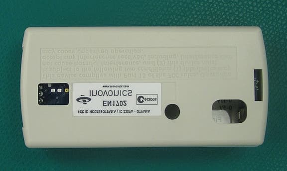
Click to zoom
Application Details
- Equipment Class
- DSS - Part 15 Spread Spectrum Transmitter
- Date of Grant
- Dec 20, 2010
- Application Purpose
- Original Equipment
- Date of Application
- Nov 10, 2010
- Equipment Note
- Dual Analog Input - Transmitter
- Frequency Range
- 902.00000000 - 928.00000000
- Country
- United States
Documents & Files
Document Text
Text extracted from the exhibit documents filed with the FCC. Open a document above to read the original.
Users Manual
© Inovonics, 2009 - www.inovonics.com EN1702 Dual Analog Sensor Transmitter Installation Instructions - 05373B 1 Overview The EN1702 transmits analog data from one or two external sensors. 1.1 Inovonics Wireless Contact Information If you have any problems with this procedure, contact Inovonics Wireless technical services: • E-mail: [email protected] • Phone: (800) 782-2709; (303) 939-9336 1.2 EN1702 Components Figure 1 EN1702 Components 2 Installation and Startup 2.1 Install/Replace the Battery 1.Pry the top lip of the mounting bracket up, and lift the bracket off of the transmitter. 2.Use your thumb to depress the housing release tab; separate the housing. 3.If replacing a battery, use the hole in the back of the housing to push the old battery out of the battery holder. 4.Install the new battery. 5.Press the Reset button to initialize the transmitter. If replacing a battery, the transmitter’s most recent programming will be restored upon initialization. 2.2 Select the Frequency Band EchoStream products are able to use a range of radio frequencies, and must be configured for your geographic area. To configure the transmitter: 1.Place a selection jumper on the appropriate frequency band selection pins. • Place the jumper on the left two pins, marked AU, to set the frequency range to 915-928 MHz for Australia. • Place the jumper on the right two pins, marked NZ, to set the frequency range to 921-928 MHz for New Zealand. • Leave the jumper off the pins to set the frequency range to 902-928 MHz for North America. 2.Press the Reset button to complete configuration. 2.3 Attach the Analog Sensors and Select Output To use the EN1702, you must connect the analog sensor(s) to one or both of the terminal blocks. To connect the analog sensors: The analog sensor cable length must not exceed three feet. 1.Place a selection jumper on the appropriate sensor output selection pins (Fig. 1C). • Place the jumper on the bottom two pins, marked 4-20mA, to select a sensor output of 4-20mA. • Place the jumper on the middle, marked 0-10V, two pins, to select a sensor range of 0-10V. • Place the jumper on the top two pins, marked 0-5V, to select a sensor range of 0-5V. 2.Referring to Figure 2, use a small screwdriver to attach the external sensor(s) wiring leads to the appropriate terminal blocks. 3.If the battery has been installed, press the Reset button to complete the procedure. Figure 2 EN1702 External Sensor Wiring 3 Program the Transmitter EN1702 transmitters are programmed at the factory. It is not usually necessary to reprogram EN1702 series transmitters. If you want to reprogram the transmitter, parameters can be changed using the programming header. 4 Mount the Transmitter 1.Attach the mounting bracket to the wall, using the included hardware. There are two mounting holes for standard installation. An optional third mounting hole is located under the battery. Use the third mounting hole to secure the housing to the bracket. 2.Hook the bottom of the transmitter into the bracket’s bottom catch, and press the transmitter into the bracket so that the bracket’s top lip snaps into place. 5 Warranty/Disclaimer Caution: Changes or modifications to this unit not expressly approved by Inovonics Wireless Corporation may void the installer's authority to operate the equipment as well as the product warranty. Inovonics Wireless Corporation ("Inovonics") warrants its EchoStream products ("Product" or "Products") to conform to its own specifications and to be free of defects in materials and workmanship under normal use for a period of thirty-six (36) months from the date of manufacture. Within the warranty period, Inovonics will repair or replace, at its option, all or any part of the warranted Product. Inovonics will not be responsible for dismantling and/or reinstallation charges. To exercise the warranty, the User ("User", "Installer" or "Consumer") must work directly through their authorized distributor who will be given a Return Material Authorization ("RMA") number by Inovonics. Details of shipment will be arranged directly through the authorized distributor. This warranty is void in cases of improper installation, misuse, failure to follow installation and operating instructions, alteration, accident or tampering, and repair by anyone other than Inovonics. This warranty is exclusive and expressly in lieu of all other warranties, obligations or liabilities, whether written, oral, express, or implied. There is no warranty by Inovonics that Inovonics product will be merchantable or fit for any particular purpose, nor is there any other warranty, expressed or implied, except as such is expressly set forth herein. In no event shall Inovonics be liable for an incidental, consequential, indirect, special, or exemplary damages, including but not limited to loss of profit, revenue, or contract, loss of use, cost of down time, or interruption of business, nor any claim made by distributor's customers or any other person or entity. This warranty will not be modified or extended. Inovonics does not authorize any person to act on its behalf to modify or extend this warranty. This warranty will apply only to Inovonics Products. Inovonics will not be liable for any direct, incidental, or consequential damage or loss whatsoever, caused by the malfunction of Product due to products, accessories, or attachments of other manufacturers, including batteries, used in conjunction with Inovonics Products. AFirst external sensor terminal block BSecond external sensor terminal block CSensor output selection pins DFrequency band selection pins EReset buttonFBattery GProgramming headerHHousing release tab A B E D F C G H 4-20 mA 4-20 mA 0-10V 0-5V 0-10V 0-5V GND GND First SensorSecond Sensor
External Photos
FCC ID: HCQ3B6OT9ANA EN1702 Page 1 External Photos: Back of product showing FCC ID Number. Front of product
ID Label/Location Info
`lkcfabkqf^i=al`rjbkq i_iJ`bJbkNTMO MRPTQ^ `lkcfabkqf^i=al`rjbkq^qflk qÜÉ=áåÑçêã~íáçå=Åçåí~áåÉÇ=áå=íÜáë=ÇçÅìãÉåí=áë=ÅçåÑáÇÉåíá~ä=íç=~åÇ=íÜÉ=ëçäÉ=éêçéÉêíó=çÑ=fåçîçåáÅë=`çêéçê~íáçåK oÉÅÉáéí=çÑ=íÜáë=áåÑçêã~íáçå=êÉèìáêÉë=íÜÉ=ÉñáëíÉåÅÉ=~åÇ=Ñìää=~ÅÅÉéí~åÅÉ=çÑ=íÜÉ=íÉêãë=~åÇ=ÅçåÇáíáçåë=çÑ=~=kçå aáëÅäçëìêÉ=^ÖêÉÉãÉåí=ëáÖåÉÇ=Äó=íÜÉ=fåçîçåáÅë=`çêéçê~íáçå=~åÇ=íÜÉ=oÉÅáéáÉåíK==qÜáë=ÇçÅìãÉåí~íáçå=áë=åçí=íç=ÄÉ êÉéêçÇìÅÉÇ=çê=êÉÇáëíêáÄìíÉÇ=ÉñÅÉéí=~ë=éêçîáÇÉÇ=áå=íÜÉ=kçå=aáëÅäçëìêÉ=^ÖêÉÉãÉåíK j^qbof^iWKMMO?=qef`h=tefqb=jvi^o==tfqe==KMMN?==j^qqb=i^jfk^qflk=Eclo=molqb`qflk=colj=fkh=pjb^ofkdF ^ka=mboj^kbkq=^aebpfsb=^mmifba=ql=qeb=_^`hpfabK=oçep=`ljmif^kq=j^qbof^ip=obnrfobaK ^oqtlohWprmmifba=_v=fklslkf`p qbuqW=_i^`h i^_bi=pfwbW=NKOOM?=u=KMKQRR?=Epeltk=ql=P=qfjbp=p`^ibFI=±pe^om=`lokbop≤=^ka=kl=_loabo m^`h^dfkd=^ka=i^_bi=lofbkq^qflkWi^_bip=ql=_b=prmmifba=lk=qlm=pfab=lc=olii=pql`h=tfqe=qbuq=ob^aJ ^_ib=^p=sfbtba=colj=_lqqlj=EpeloqF=badb=lc=olii= oÉîK=iÉîÉä aÉëÅêáéíáçåa~íÉ ^fåáíá~ä=oÉäÉ~ëÉMVLMOLOMMU `çåÑáÇÉåíá~ä=íç=fåçîçåáÅë ïïïKáåçîçåáÅëKÅçã c``=fa=e`nP_SlqV^k^=L=f`=OPMV^=J=lqV^k^ bkNTMO
Internal Photos
FCC ID: HCQ3B6OT9ANA EN1702 Page 1 Internal Photos: PCB FRONT Trace Antenna FCC ID: HCQ3B6OT9ANA EN1702 Page 2 Internal Photos (cont’d): PCB Back
Test Report
Project File: 3164931 Page 1 of 26 Intertek Testing Services NA, Inc. 5541 Central Avenue, Suite 110 Boulder, Colorado 80301 Voice: 303 786 7999 Fax: 303 449 6160 Rev.No 1 EMC EMISSIONS - TEST REPORT (In Part) Test Report No. 3164931DEN-004F-CSA Issue Date: Thursday 18/Dec/2008 Model / Serial No. MN: EN1702 /SN: 3711619 Product Type Wireless Temperature Sensor Client Inovonics Wireless Corporation Manufacturer Inovonics Wireless Corporation License holder Inovonics Wireless Corporation 315 - CTC Boulevard Address Louisville, CO 80027 Test Criteria Applied FCC 47 CFR Part 15.247 IC RSS-210 Issue 7 Test Result PASS Test Project Number References 3164931 Total Pages Including Appendices: 26 Title 47 CFR 15: RADIO FREQUENCY DEVICES Subpart C – Intentional Radiators Low-power License-exempt Radio Communication Devices (All Frequency Bands): Category 1 Equipment Tested By : Randy Thompson Reviewed By: Michael Spataro REVISION SUMMARY - The following changes have been made to this Report: Rev. Revision Statement Author Revision Date Reviewer Initial Release of Document See above See above A Update report to include RSS-210 Notes| per Quote 500177658 9-29-09 Michael Spataro This report is for the exclusive use of Intertek's Client and is provided pursuant to the agreement between Intertek and its Client. Intertek's responsibility and liability are limited to the terms and conditions of the agreement. Intertek assumes no liability to any party, other than to the Client in accordance with the agreement, for any loss, expense or damage occasioned by the use of this report. Only the Client is authorized to copy or distribute this report and then only in its entirety. Any use of the Intertek name or one of its marks for the sale or advertisement of the tested material, product or service must first be approved in writing by Intertek. The observations and test results in this report are relevant only to the sample tested. This report by itself does not imply that the material, product, or service is or has ever been under an Intertek certification program. This report must not be used to claim product endorsement by NVLAP, NIST nor any other agency of the U.S. Government. Measurement uncertainty is not incorporated in to the PASS/FAIL results as stated above. A statement of uncertainty is made on page 2 and is for informational purposes. Project File: 3164931 Page 2 of 26 Intertek Testing Services NA, Inc. 5541 Central Avenue, Suite 110 Boulder, Colorado 80301 Voice: 303 786 7999 Fax: 303 449 6160 Rev.No 1 D I R E C T O R Y Documentation Page(s) Test report 1 - 26 Directory 2 Test Regulations 3 General Remarks 4 Test-setup Photographs 5 - 6 Appendix A Test Data Sheets and Test Equipment Used 7 - 13 Appendix B Test Plan/Constructional Data Form 14 - 21 Appendix C Measurement Protocol/Test Procedures 22 - 26 STATEMENT OF MEASUREMENT UNCERTAINTY The data and results referenced in this document are true and accurate. The measurement uncertainty for Conducted Emissions in the frequency range of 150kHz – 30MHz is calculated to be 3.14dB and for Radiated Emissions is calculated to be 4.4dB in the frequency range of 10kHz – 1000MHz at 3m and 4.9dB in the frequency range of 1 – 18GHz at 3m. For testing at 10m 4.8dB in the frequency range of 30 – 1000MHz. For Disturbance Power, 3.3dB in the frequency range of 30 – 1000MHz. For Flicker and Harmonics testing the equipment used is calibrated by the manufacture and is with in the tolerances specified in 61000-3-2/3. These uncertainties have been calculated using CISPR 16-4-2:2003 and represent a 95% confidence level (k=2). EUT Received Date: 5-November-2008 Testing Start Date: 5-November-2008 Testing End Date: 5-November-2008 Project File: 3164931 Page 3 of 26 Intertek Testing Services NA, Inc. 5541 Central Avenue, Suite 110 Boulder, Colorado 80301 Voice: 303 786 7999 Fax: 303 449 6160 Rev.No 1 The tests were performed according to following regulations: 1. FCC CFR47 Part 15 subpart C 2. IC RSS-210e Issue 7 2007 3. IC RSS-GEN Issue 2 2007 Emission Test Results: Conducted Emissions 15.207 - NA Test Result Minimum limit margin 0.0 dB at 0.0 MHz Remarks: EUT is powered via battery. Radiated Unintentional and Spurious Emissions 15.247(D) /15.205/209 - NA Test Result Minimum limit margin 0.0 dB at 0.0 MHz Remarks: Covers RSS-210 section 2.7 Tables 1 and 2. Radiated Unintentional and Spurious Emissions for this product were tested and covered in a separate report. Refer to Report 3164931DEN-004B for details. Peak Output Power – Fundamental: 15.247 (b)(2) - PASS Test Result Minimum limit margin - 1.1 dB at 902.41 MHz Remarks: Covers RSS-210 Annex 8. Low Channel Radiated Emissions – Harmonics of the Fundamental: 15.205/15.247(d) - PASS Test Result Minimum limit margin - 0.5 dB at 7420.93 MHz Remarks: Covers RSS-210 Section 2.7 Tables 1 and 2 High Channel Project File: 3164931 Page 4 of 26 Intertek Testing Services NA, Inc. 5541 Central Avenue, Suite 110 Boulder, Colorado 80301 Voice: 303 786 7999 Fax: 303 449 6160 Rev.No 1 GENERAL REMARKS: The following remarks are to be considered as “where applicable“ and are taken into account while completing any FCC/IC/ETSI radio tests at Intertek. Testing was performed in 3 different orthogonal axis to determine the worst case emissions from the device. The worst case emissions measurements are shown in this report. FCC CFR47 Part 15.31: Measurement Standards: In any case where the device is powered off a battery, a fresh battery was used during test. In cases where the device is powered off an AC supply, voltage was varied per Part 15.31 to find worst case emissions. FCC CFR47 Part 15.35: Measurement Detector Functions and Bandwidths: FCC Part 15.35 was utilized when performing the measurements within this report. Whenever possible the approved test procedures specified in FCC DA 00-705 for FHSS devices was used for testing. Limit Calculation: At the time of testing, Intertek was unable to obtain the gain of the antenna for the…
Text truncated - open the document above for the full version.
Test Report
Project File: 3164931 Page 1 of 22 Intertek 5541 Central Avenue, Suite 110 Boulder, Colorado 80301 Voice: 303 786 7999 Fax: 303 449 6160 EMC EMISSIONS - TEST REPORT (Full) Test Report No. 3164931DEN-004B Issue Date: Wednesday 26/Nov/2008 Model / Serial No. Model: EE/EN Series [Details on Page 3] Product Type Wireless Temperature Sensors Client Inovonics Wireless Corporation Manufacturer Inovonics Wireless Corporation License holder Inovonics Wireless Corporation 315 CTC Boulevard Address Louisville, CO 80027 Test Criteria Applied CISPR 22: 2005 Class B Test Result PASS Test Project Number References 3164931 Total Pages Including Appendices: 22 INFORMATION TECHNOLOGY EQUIPMENT - RADIO DISTURBANCE CHARACTERISTICS - LIMITS AND METHODS AND MEASUREMENTS Report Includes: IEC/EN 61000-3-2 and IEC/EN 61000-3-3 Where applicable Tested By : Randy Thompson Reviewed By : Michael Spataro REVISION SUMMARY - The following changes have been made to this Report: Rev. Revision Statement Author Revision Date Reviewer Initial Release of Document See above See above This report is for the exclusive use of Intertek's Client and is provided pursuant to the agreement between Intertek and its Client. Intertek's responsibility and liability are limited to the terms and conditions of the agreement. Intertek assumes no liability to any party, other than to the Client in accordance with the agreement, for any loss, expense or damage occasioned by the use of this report. Only the Client is authorized to copy or distribute this report and then only in its entirety. Any use of the Intertek name or one of its marks for the sale or advertisement of the tested material, product or service must first be approved in writing by Intertek. The observations and test results in this report are relevant only to the sample tested. This report by itself does not imply that the material, product, or service is or has ever been under an Intertek certification program. This report must not be used to claim product endorsement by NVLAP, NIST nor any other agency of the U.S. Government. Measurement uncertainty is not incorporated in to the PASS/FAIL results as stated above. A statement of uncertainty is made on page 2 and is for informational purposes. Project File: 3164931 Page 2 of 22 Intertek 5541 Central Avenue, Suite 110 Boulder, Colorado 80301 Voice: 303 786 7999 Fax: 303 449 6160 Rev.No 1 D I R E C T O R Y Documentation Page(s) Test report 1 - 22 Directory 2 Test Regulations 3 General Remarks 3 Test-setup Photographs 4 - 7 Appendix A Test Data Sheets and Test Equipment Used 8 - 15 Appendix B Test Plan/Constructional Data Form 16 - 17 Appendix C Measurement Protocol/Test Procedures 18 - 22 STATEMENT OF MEASUREMENT UNCERTAINTY The data and results referenced in this document are true and accurate. The measurement uncertainty for Conducted Emissions in the frequency range of 150kHz – 30MHz is calculated to be ±3.14dB and for Radiated Emissions is calculated to be ±4.4dB in the frequency range of 10kHz – 1000MHz at 3m and ±4.9dB in the frequency range of 1 – 18GHz at 3m. For testing at 10m ±4.8dB in the frequency range of 30 – 1000MHz. For Disturbance Power, ±3.3dB in the frequency range of 30 – 1000MHz. For Flicker and Harmonics testing the equipment used is calibrated by the manufacture and is with in the tolerances specified in 61000-3-2/3. These uncertainties have been calculated using CISPR 16-4-2:2003 and represent a 95% confidence level (k=2). EUT Received Date: 28-Oct-2008 Testing Start Date: 28-Oct-2008 Testing End Date: 28-Oct-2008 Project File: 3164931 Page 3 of 22 Intertek 5541 Central Avenue, Suite 110 Boulder, Colorado 80301 Voice: 303 786 7999 Fax: 303 449 6160 Rev.No 1 The tests were performed according to following regulations: 1. EMC Directive 2004/108/EC 2. IEC/CISPR 22: 1997, +A1: 2000, +A2: 2002 3. EN 55022: 1998, +A1: 2000, +A2: 2003 4. FCC CFR47 Part 15 5. AS/NZS CISPR22: 2004/ VCCI-03: 2004 6. ICES-003, Issue-4 Emission Test Results: Conducted Emissions, Powerline - N/A Test Result Minimum limit margin 00.00 dB at 0000.00 MHz Remarks: Product is 3.3 VDC battery-powered Radiated Emissions (Electric Field) - PASS Test Result Minimum limit margin - 5.8 dB at 145.23 MHz Remarks: Quasi-peak Measurement - Vertical GENERAL REMARKS: Product is 3.3 VDC battery-powered; therefore, no AC port testing required. All Products are wireless temperature sensors Products tested in a “bundle” per client request: Model: EE1723 S/N: 3921349 EU Model Model: EN1723 S/N: 3791981 NA Model Model: EE1702 S/N: 3949739 EU Model Model: EN1702 S/N: 3972129 NA Model The following models are included per Declaration of Similarity [DoS]. Refer to Appendix B Model: EE1722 & Model: EN 1722 Sample: Production Prototype See Appendix B Modifications required to pass: None Test Specification Deviations: Additions to or Exclusions from: None Project File: 3164931 Page 4 of 22 Intertek 5541 Central Avenue, Suite 110 Boulder, Colorado 80301 Voice: 303 786 7999 Fax: 303 449 6160 Rev.No 1 Test-setup photo(s): Radiated Emissions Project File: 3164931 Page 5 of 22 Intertek 5541 Central Avenue, Suite 110 Boulder, Colorado 80301 Voice: 303 786 7999 Fax: 303 449 6160 Rev.No 1 Test-setup photo(s): Radiated Emissions Project File: 3164931 Page 6 of 22 Intertek 5541 Central Avenue, Suite 110 Boulder, Colorado 80301 Voice: 303 786 7999 Fax: 303 449 6160 Rev.No 1 Test-setup photo(s): Radiated Emissions – Product ID Project File: 3164931 Page 7 of 22 Intertek 5541 Central Avenue, Suite 110 Boulder, Colorado 80301 Voice: 303 786 7999 Fax: 303 449 6160 Rev.No 1 Test-setup photo(s): Radiated Emissions – Product ID Project File: 3164931 Page 8 of 22 Intertek 5541 Central Avenue, Suite 110 Boulder, Colorado 80301 Voice: 303 786 7999 Fax: 303 449 6160 Rev.No 1 Appendix A Test Data Sheets and Test Equipment Used Project File: 3164931 Page 9 of 22 Intertek 5541 Central Avenue, Suite 110 Boulder, Colorado 80301 Voice: 303 786 7999 Fax: 303 449 6160 Rev.No 1 Radiat…
Text truncated - open the document above for the full version.
Test Report
FCC ID: HCQ3B6OT9ANA EN1702 Page 1 Test Report Additional Information: In addition to the intentional and unintentional emissions lab test reports submitted with this application, additional test data demonstrating compliance with CFR47, 15.247 follows. For the following measurements, the antenna was replaced by a coaxial connection to a MXA N9020A spectrum analyzer. Minimum Channel Separation: Plot 1 is a spectrum plot showing a minimum channel separation of 800 kHz. Compliance with section 15.247(a)(1) is demonstrated by capturing several transmissions over a small portion of the 902-928 MHz ISM band. Plot 1: Demonstration of channel spacing requirement. FCC ID: HCQ3B6OT9ANA EN1702 Page 2 Number of hopping Channels: Plot 2 demonstrates compliance with 15.247(a)(1)(i) — Number of hopping channels. This is a stored display of many sequential transmissions to show the overall band occupied by the transmitter. The marker at 903.63 MHz represents the maximum conducted transmitter power across the band. Plot 2: Demonstration of 25 hopping channels. FCC ID: HCQ3B6OT9ANA EN1702 Page 3 20 dB bandwidth of a single channel: Plot 3 shows the 20 dB bandwidth of a single channel to demonstrate compliance with 15.247(a)(1)(i). The 20 dB occupied bandwidth is 289.54 kHz. Plot 3: Demonstration of occupied bandwidth.
Test Report
FCC ID: HCQ3B6OT9ANA EN1702 Test Report Additional Information_2: Alternative to Conducted Output Power Measurements: Required conducted power output measurements at low, medium, and high channels (per 15.247(b) and (c)) could not be performed directly since the transmit antenna is integrated onto the printed circuit board. However, compliance with these requirements has been achieved by way of performing and passing the radiated tests described in the ALTERNATIVE TEST PROCEDURES in Public Notice DA 00-705, March 30, 2000. Specifically, all radiated emissions shown in the test report are less than 119.2 dBuV/m at 3 meters. This is the field strength limit corresponding to the maximum fundamental power output of 0.25 watts from an isotropic antenna per 15.247 (b) (2) for systems employing between 25 and 49 hopping channels. The calculation as detailed in the above Public Notice is as follows: E = Square Root of (30PG) all divided by d E = 912,871 uV/m = 119.21 dB uV/m where E is the maximum allowable fundamental field strength in uV/m P is the maximum allowable fundamental radiated power = 0.25 watts G is the antenna gain = 1 (Assume 1 for the worst case (lowest allowable) final field strength.) d is the measured distance = 3 meters
Test Report
Project File: 3164931 Page 1 of 26 Intertek Testing Services NA, Inc. 5541 Central Avenue, Suite 110 Boulder, Colorado 80301 Voice: 303 786 7999 Fax: 303 449 6160 Rev.No 1 EMC EMISSIONS - TEST REPORT (In Part) Test Report No. 3164931DEN-004F-CSA Issue Date: Thursday 18/Dec/2008 Model / Serial No. MN: EN1702 /SN: 3711619 Product Type Wireless Temperature Sensor Client Inovonics Wireless Corporation Manufacturer Inovonics Wireless Corporation License holder Inovonics Wireless Corporation 315 - CTC Boulevard Address Louisville, CO 80027 Test Criteria Applied FCC 47 CFR Part 15.247 IC RSS-210 Issue 7 Test Result PASS Test Project Number References 3164931 Total Pages Including Appendices: 26 Title 47 CFR 15: RADIO FREQUENCY DEVICES Subpart C – Intentional Radiators Low-power License-exempt Radio Communication Devices (All Frequency Bands): Category 1 Equipment Tested By : Randy Thompson Reviewed By: Michael Spataro REVISION SUMMARY - The following changes have been made to this Report: Rev. Revision Statement Author Revision Date Reviewer Initial Release of Document See above See above A Update report to include RSS-210 Notes| per Quote 500177658 9-29-09 Michael Spataro This report is for the exclusive use of Intertek's Client and is provided pursuant to the agreement between Intertek and its Client. Intertek's responsibility and liability are limited to the terms and conditions of the agreement. Intertek assumes no liability to any party, other than to the Client in accordance with the agreement, for any loss, expense or damage occasioned by the use of this report. Only the Client is authorized to copy or distribute this report and then only in its entirety. Any use of the Intertek name or one of its marks for the sale or advertisement of the tested material, product or service must first be approved in writing by Intertek. The observations and test results in this report are relevant only to the sample tested. This report by itself does not imply that the material, product, or service is or has ever been under an Intertek certification program. This report must not be used to claim product endorsement by NVLAP, NIST nor any other agency of the U.S. Government. Measurement uncertainty is not incorporated in to the PASS/FAIL results as stated above. A statement of uncertainty is made on page 2 and is for informational purposes. Project File: 3164931 Page 2 of 26 Intertek Testing Services NA, Inc. 5541 Central Avenue, Suite 110 Boulder, Colorado 80301 Voice: 303 786 7999 Fax: 303 449 6160 Rev.No 1 D I R E C T O R Y Documentation Page(s) Test report 1 - 26 Directory 2 Test Regulations 3 General Remarks 4 Test-setup Photographs 5 - 6 Appendix A Test Data Sheets and Test Equipment Used 7 - 13 Appendix B Test Plan/Constructional Data Form 14 - 21 Appendix C Measurement Protocol/Test Procedures 22 - 26 STATEMENT OF MEASUREMENT UNCERTAINTY The data and results referenced in this document are true and accurate. The measurement uncertainty for Conducted Emissions in the frequency range of 150kHz – 30MHz is calculated to be 3.14dB and for Radiated Emissions is calculated to be 4.4dB in the frequency range of 10kHz – 1000MHz at 3m and 4.9dB in the frequency range of 1 – 18GHz at 3m. For testing at 10m 4.8dB in the frequency range of 30 – 1000MHz. For Disturbance Power, 3.3dB in the frequency range of 30 – 1000MHz. For Flicker and Harmonics testing the equipment used is calibrated by the manufacture and is with in the tolerances specified in 61000-3-2/3. These uncertainties have been calculated using CISPR 16-4-2:2003 and represent a 95% confidence level (k=2). EUT Received Date: 5-November-2008 Testing Start Date: 5-November-2008 Testing End Date: 5-November-2008 Project File: 3164931 Page 3 of 26 Intertek Testing Services NA, Inc. 5541 Central Avenue, Suite 110 Boulder, Colorado 80301 Voice: 303 786 7999 Fax: 303 449 6160 Rev.No 1 The tests were performed according to following regulations: 1. FCC CFR47 Part 15 subpart C 2. IC RSS-210e Issue 7 2007 3. IC RSS-GEN Issue 2 2007 Emission Test Results: Conducted Emissions 15.207 - NA Test Result Minimum limit margin 0.0 dB at 0.0 MHz Remarks: EUT is powered via battery. Radiated Unintentional and Spurious Emissions 15.247(D) /15.205/209 - NA Test Result Minimum limit margin 0.0 dB at 0.0 MHz Remarks: Covers RSS-210 section 2.7 Tables 1 and 2. Radiated Unintentional and Spurious Emissions for this product were tested and covered in a separate report. Refer to Report 3164931DEN-004B for details. Peak Output Power – Fundamental: 15.247 (b)(2) - PASS Test Result Minimum limit margin - 1.1 dB at 902.41 MHz Remarks: Covers RSS-210 Annex 8. Low Channel Radiated Emissions – Harmonics of the Fundamental: 15.205/15.247(d) - PASS Test Result Minimum limit margin - 0.5 dB at 7420.93 MHz Remarks: Covers RSS-210 Section 2.7 Tables 1 and 2 High Channel Project File: 3164931 Page 4 of 26 Intertek Testing Services NA, Inc. 5541 Central Avenue, Suite 110 Boulder, Colorado 80301 Voice: 303 786 7999 Fax: 303 449 6160 Rev.No 1 GENERAL REMARKS: The following remarks are to be considered as “where applicable“ and are taken into account while completing any FCC/IC/ETSI radio tests at Intertek. Testing was performed in 3 different orthogonal axis to determine the worst case emissions from the device. The worst case emissions measurements are shown in this report. FCC CFR47 Part 15.31: Measurement Standards: In any case where the device is powered off a battery, a fresh battery was used during test. In cases where the device is powered off an AC supply, voltage was varied per Part 15.31 to find worst case emissions. FCC CFR47 Part 15.35: Measurement Detector Functions and Bandwidths: FCC Part 15.35 was utilized when performing the measurements within this report. Whenever possible the approved test procedures specified in FCC DA 00-705 for FHSS devices was used for testing. Limit Calculation: At the time of testing, Intertek was unable to obtain the gain of the antenna for the…
Text truncated - open the document above for the full version.
Test Setup Photos
© Inovonics, 2009 - www.inovonics.com EN1702 Dual Analog Sensor Transmitter Installation Instructions - 05373B 1 Overview The EN1702 transmits analog data from one or two external sensors. 1.1 Inovonics Wireless Contact Information If you have any problems with this procedure, contact Inovonics Wireless technical services: • E-mail: [email protected] • Phone: (800) 782-2709; (303) 939-9336 1.2 EN1702 Components Figure 1 EN1702 Components 2 Installation and Startup 2.1 Install/Replace the Battery 1.Pry the top lip of the mounting bracket up, and lift the bracket off of the transmitter. 2.Use your thumb to depress the housing release tab; separate the housing. 3.If replacing a battery, use the hole in the back of the housing to push the old battery out of the battery holder. 4.Install the new battery. 5.Press the Reset button to initialize the transmitter. If replacing a battery, the transmitter’s most recent programming will be restored upon initialization. 2.2 Select the Frequency Band EchoStream products are able to use a range of radio frequencies, and must be configured for your geographic area. To configure the transmitter: 1.Place a selection jumper on the appropriate frequency band selection pins. • Place the jumper on the left two pins, marked AU, to set the frequency range to 915-928 MHz for Australia. • Place the jumper on the right two pins, marked NZ, to set the frequency range to 921-928 MHz for New Zealand. • Leave the jumper off the pins to set the frequency range to 902-928 MHz for North America. 2.Press the Reset button to complete configuration. 2.3 Attach the Analog Sensors and Select Output To use the EN1702, you must connect the analog sensor(s) to one or both of the terminal blocks. To connect the analog sensors: The analog sensor cable length must not exceed three feet. 1.Place a selection jumper on the appropriate sensor output selection pins (Fig. 1C). • Place the jumper on the bottom two pins, marked 4-20mA, to select a sensor output of 4-20mA. • Place the jumper on the middle, marked 0-10V, two pins, to select a sensor range of 0-10V. • Place the jumper on the top two pins, marked 0-5V, to select a sensor range of 0-5V. 2.Referring to Figure 2, use a small screwdriver to attach the external sensor(s) wiring leads to the appropriate terminal blocks. 3.If the battery has been…
Text truncated - open the document above for the full version.
Contact Information
Applicant
Jess Cobb(Manager of Program Mgmt)
Technical Contact
Inovonics Wireless CorpDaryl Burkhard
[email protected]303-209-7145
Louisville, Colorado · United States
Non-Technical Contact
Inovonics Wireless CorpKeal Vigil
[email protected]303-209-7113
Test Firm
Intertek Testing Services NA, Inc.Jay Kogoma
Technical Specifications
| # | Rule Parts | Frequency Range | Power Output | Emission | Tolerance |
|---|---|---|---|---|---|
| 1 | 15C | 902 MHz - 928 MHz | 50.00 mW | 250KFID | 30.0000000000 ppm |
Other Applications from Inovonics Wireless Corporation

HCQ-IDTOUCH1
May 13, 2026Inovonics Wired Touchscreen Keypad
Equipment Class
DTS - Digital Transmission System
HCQBWA02
Aug 28, 2024Flush Mount Locator
Equipment Class
DSS - Part 15 Spread Spectrum Transmitter
HCQTBA
Sep 21, 2022TBA Module
Equipment Class
DSS - Part 15 Spread Spectrum Transmitter
HCQPFA01
Jul 14, 2022Fall Detect Transmitter
Equipment Class
DSS - Part 15 Spread Spectrum Transmitter
HCQ3B6BRGSA
Sep 22, 2020Bluetooth to EchoStream Bridge
Equipment Class
DTS - Digital Transmission System