HCQ3B6OT9ESLSmoke Detector - Transmitter
Inovonics Wireless Corporation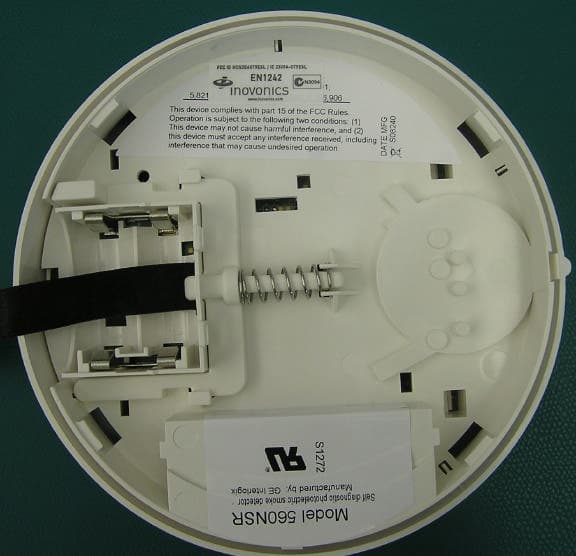
Click to zoom
Application Details
- Equipment Class
- DSS - Part 15 Spread Spectrum Transmitter
- Date of Grant
- Dec 09, 2010
- Application Purpose
- Original Equipment
- Date of Application
- Nov 10, 2010
- Equipment Note
- Smoke Detector - Transmitter
- Frequency Range
- 902.00000000 - 928.00000000
- Country
- United States
Documents & Files
Document Text
Text extracted from the exhibit documents filed with the FCC. Open a document above to read the original.
Users Manual
© Inovonics, 2009 - www.inovonics.com EN1242 EchoStream ® Smoke Detector Transmitter Installation Instructions - 05362F 1 Overview The EN1242 smoke detector is a wireless, battery powered photoelectric smoke sensor. The sensor includes a built-in sounder for alarm alerts, a visual status LED, and an Inovonics Wireless EchoStream transmitter. The sensor works as part of a security/fire alarm system and communicates with the system control panel. Under normal (non-alarm) conditions, the LED flashes once every eight seconds while the sensor monitors the surrounding conditions. When the sensor detects smoke, the LED lights, the built-in sounder beeps loudly, and an alarm signal is transmitted. The smoke sensor is powered by the two included three-volt lithium batteries. When the EN1242 detects an inactive smoke sensor a tamper message will be transmitted. Note: For UL installations, refer to the EN4216R Installation and Operation Manual or the EN7285 Installation Instructions. 1.1 Inovonics Wireless Contact Information If you have any problems with this procedure, contact Inovonics Wireless technical services: • E-mail: [email protected] • Phone: (800) 782-2709; (303) 939-9336 1.2 EN1242 Components Figure 1 EN1242 Components 1.3 EN1242 Features Figure 2 EN1242 Features 2 Installation and Startup 2.1 Install Batteries 1.Turn the sensor housing counterclockwise 15 degrees and detach it from the mounting base. 2.Remove the battery compartment cover. Figure 3 EN1242 Battery Compartment Cover 3.Install/replace the two three-volt batteries. Note: A tamper message will transmit for approximately ten seconds while the unit powers up after the installation of both batteries. If only one battery is installed, the tamper message will transmit continuously. 2.2 Open the Housing 1.Using a small screwdriver to press the sensor cap release tab, apply downward pressure and turn the cap about one inch counter-clockwise to remove the cap.. Figure 4 Remove the Sensor Cap 2.Place both thumbs on either side of the optical chamber and push down to detach the sensor housing. Figure 5 Push Down on the Optical Chamber 2.3 Select the Frequency Band EchoStream products are able to use a range of radio frequencies, and must be configured for your geographic area. To configure the transmitter: 1.Place a selection jumper on the appropriate frequency band selection pins. • Place the jumper on the left two pins, marked AU, to set the frequency range to 915-928 MHz for Australia. • Place the jumper on the right two pins, marked NZ, to set the frequency range to 921-928 MHz for New Zealand. • Leave the jumper off the pins to set the frequency range to 902-928 MHz for North America. 2.Press the Reset button to complete configuration. Caution: When pressing the Reset button, make sure you don’t also touch the frequency band selection pins. Touching the frequency band selection pins while pressing the Reset button can inadvertently set the device to the wrong frequency band. ALow Battery/Clean Me Selection Pins B Frequency Band Selection Pins CReset Button ASounder VentBLEDCTest/Silence Button A B C A C B Battery Compartment © Inovonics, 2009 - www.inovonics.com 2 2.4 Set CleanMe ® /Low Battery Reporting Set as the factory default, the EN1242 combines the low battery signal with a signal indicating the detector needs cleaning. If multiple-condition indication is not desired, wireless reporting of the CleanMe status can be disabled by moving the jumper on the low battery/CleanMe selection pins to Low Bat. When this is done, only a low battery signal will be sent from the detector. Note: Low battery/CleanMe messages are suppressed when an alarm is being transmitted. Note: Even if CleanMe notification is disabled, the sensitivity test will still indicate sensor condition. 2.5 Register the EN1242 The EN1242 must be registered to function in your EchoStream system. Refer to your receiver, network coordinator or control panel manual for registration instructions. Inovonics Wireless recommends all EchoStream transmitters be supervised. When prompted, you will press the EN1242 Reset button to complete registration. 2.6 Mount the EN1242 1.Use the provided anchors and screws to mount the EN1242, paying careful consideration to the following best practices: Caution: Regulations pertaining to smoke sensor installations vary. For more information, contact your local fire department or local authority having jurisdiction. • Install a minimum of two smoke sensors in any household. • Put a smoke sensor in the hallway outside of every bedroom area. • Put a smoke sensor on every level of a multi-level residence. • In rooms with sloped ceilings, install smoke sensors 0.9m (3 feet) measured down from the highest point of the ceiling. • Install basement sensors on the ceiling as close to the center of the room as possible. If this is not practical, install on the ceiling no closer than 10cm (4 inches) from any wall or corner. • If ceiling mounting is not practical, install on an inside wall between 10 an 15cm (4 and 6 inches) from the ceiling. • Put smoke sensors at both ends of a bedroom hallway if the hallway is more than 9m (30 feet) long. Large rooms over 84 square meters (900 square feet) require more than a single sensor. • Areas with rough ceilings or short, transom-type walls coming down from the ceiling require additional smoke sensors. • Install second-floor smoke sensors on the ceiling at the top of the first- to-second floor stairwell. Be sure that no door or other obstruction blocks the path of smoke to the sensor. Do not locate sensors: • To a drop ceiling tile; mount it to a metal runner. • In or near areas such as kitchens or garages, where smoke or vehicle exhausts normally occur (protect these areas with heat-detection devices, not with smoke sensors); near furnaces, hot water heaters, or gas space heaters. • In damp or very humid areas, or next to bathrooms with showers. Install sensors at least 1.5m (5 feet) away from bathro…
Text truncated - open the document above for the full version.
Cover Letter(s)
November 10, 2010 Federal Communications Commission Authorization and Standards Division 7435 Oakland Mills Road Columbia, MD 21046 Subject: Request for Confidentiality for FCC ID# HCQ3B6OT9ESL Gentlemen: The following documents being submitted with the Application for Equipment Authorization for FCC ID# HCQ3B6OT9ESL are marked “Confidential”. We request that you maintain these documents in the non-public file and withhold them from public inspection, pursuant to Sections 0.457(d) and 0.459 of the Commission’s Rules, and Section 552(b)(4) of the Freedom of Information Act. This confidentiality is necessary to protect proprietary information, and falls under the category of “Trade Secrets”. 1) Operational Description 2) Schematics 3) Block Diagram Thanks for your help. Sincerely, Keal Vigil Production Control Specialist II Inovonics Wireless Corp. 303-209-7113 [email protected]
External Photos
FCC ID: HCQ3B6OT9ESL EN1242 Page 1 External Photos: Front of product FCC ID: HCQ3B6OT9ESL EN1242 Page 2 External Photos (cont’d): Back of product showing FCC ID Number.
ID Label/Location Info
`lkcfabkqf^i=al`rjbkq i_iJc``JbkNOQO MRPSP^ `lkcfabkqf^i=al`rjbkq^qflk qÜÉ=áåÑçêã~íáçå=Åçåí~áåÉÇ=áå=íÜáë=ÇçÅìãÉåí=áë=ÅçåÑáÇÉåíá~ä=íç=~åÇ=íÜÉ=ëçäÉ=éêçéÉêíó=çÑ=fåçîçåáÅë=`çêéçê~íáçåK oÉÅÉáéí=çÑ=íÜáë=áåÑçêã~íáçå=êÉèìáêÉë=íÜÉ=ÉñáëíÉåÅÉ=~åÇ=Ñìää=~ÅÅÉéí~åÅÉ=çÑ=íÜÉ=íÉêãë=~åÇ=ÅçåÇáíáçåë=çÑ=~=kçå aáëÅäçëìêÉ=^ÖêÉÉãÉåí=ëáÖåÉÇ=Äó=íÜÉ=fåçîçåáÅë=`çêéçê~íáçå=~åÇ=íÜÉ=oÉÅáéáÉåíK==qÜáë=ÇçÅìãÉåí~íáçå=áë=åçí=íç=ÄÉ êÉéêçÇìÅÉÇ=çê=êÉÇáëíêáÄìíÉÇ=ÉñÅÉéí=~ë=éêçîáÇÉÇ=áå=íÜÉ=kçå=aáëÅäçëìêÉ=^ÖêÉÉãÉåíK oÉîK=iÉîÉä aÉëÅêáéíáçåa~íÉ ^fåáíá~ä=oÉäÉ~ëÉMULNQLOMMU «=fåçîçåáÅë=táêÉäÉëë=`çêéçê~íáçå=OMMU j^qbof^iWKMMO?=qef`h=tefqb=jvi^o==tfqe==KMMN?==j^qqb=i^jfk^qflk=Eclo=molqb`qflk=colj=fkh=pjb^ofkdF ^ka=mboj^kbkq=^aebpfsb=^mmifba=ql=qeb=_^`hpfabK=oçep=`ljmif^kq=j^qbof^ip=obnrfobaK ^oqtlohWprmmifba=_v=fklslkf`p qbuqW=_i^`h i^_bi=pfwbW=NKOOM?=u=KMKQRR?=Epeltk=ql=P=qfjbp=p`^ibFI=±pe^om=`lokbop≤=^ka=kl=_loabo m^`h^dfkd=^ka=i^_bi=lofbkq^qflkWi^_bip=ql=_b=prmmifba=lk=qlm=pfab=lc=olii=pql`h=tfqe=qbuq=ob^aJ ^_ib=^p=sfbtba=colj=_lqqlj=EpeloqF=badb=lc=olii= ïïïKáåçîçåáÅëKÅçã c``=fa=e`nP_SlqVbpi=L=f`=OPMV^JlqVbpi bkNOQO
Internal Photos
FCC ID: HCQ3B6OT9ESL EN1242 Page 1 Internal Photos: Inovonics board inside of unit FCC ID: HCQ3B6OT9ESL EN1242 Page 2 Internal Photos (cont’d): PCB CLOSEUP Trace Antenna FCC ID: HCQ3B6OT9ESL EN1242 Page 3 Internal Photos (cont’d): Back of PCB
Test Report
Project File: 3162583 Page 1 of 26 Intertek Testing Services NA, Inc. 5541 Central Avenue, Suite 110 Boulder, Colorado 80301 Voice: 303 786 7999 Fax: 303 449 6160 Rev.No 1 EMC EMISSIONS - TEST REPORT (In Part) Test Report No. 3162583DEN-004D Issue Date: Thursday 18/Dec/2008 Model / Serial No. MN: EN1242 /SN: 3803179 Product Type Wireless Smoke Sensor Client Inovonics Wireless Corporation Manufacturer Inovonics Wireless Corporation License holder Inovonics Wireless Corporation 315 - CTC Boulevard Address Louisville, CO 80027 Test Criteria Applied FCC 47 CFR Part 15.247 Test Result PASS Test Project Number References 3162583 Total Pages Including Appendices: 26 Title 47 CFR 15: RADIO FREQUENCY DEVICES Subpart C – Intentional Radiators Tested By : Randy Thompson Reviewed By: Michael Spataro REVISION SUMMARY - The following changes have been made to this Report: Rev. Revision Statement Author Revision Date Reviewer Initial Release of Document See above See above This report is for the exclusive use of Intertek's Client and is provided pursuant to the agreement between Intertek and its Client. Intertek's responsibility and liability are limited to the terms and conditions of the agreement. Intertek assumes no liability to any party, other than to the Client in accordance with the agreement, for any loss, expense or damage occasioned by the use of this report. Only the Client is authorized to copy or distribute this report and then only in its entirety. Any use of the Intertek name or one of its marks for the sale or advertisement of the tested material, product or service must first be approved in writing by Intertek. The observations and test results in this report are relevant only to the sample tested. This report by itself does not imply that the material, product, or service is or has ever been under an Intertek certification program. This report must not be used to claim product endorsement by NVLAP, NIST nor any other agency of the U.S. Government. Measurement uncertainty is not incorporated in to the PASS/FAIL results as stated above. A statement of uncertainty is made on page 2 and is for informational purposes. Project File: 3162583 Page 2 of 26 Intertek Testing Services NA, Inc. 5541 Central Avenue, Suite 110 Boulder, Colorado 80301 Voice: 303 786 7999 Fax: 303 449 6160 Rev.No 1 D I R E C T O R Y Documentation Page(s) Test report 1 - 26 Directory 2 Test Regulations 3 General Remarks 4 Test-setup Photographs 5 - 6 Appendix A Test Data Sheets and Test Equipment Used 7 - 13 Appendix B Test Plan/Constructional Data Form 14 - 21 Appendix C Measurement Protocol/Test Procedures 22 - 26 STATEMENT OF MEASUREMENT UNCERTAINTY The data and results referenced in this document are true and accurate. The measurement uncertainty for Conducted Emissions in the frequency range of 150kHz – 30MHz is calculated to be ±3.14dB and for Radiated Emissions is calculated to be ±4.4dB in the frequency range of 10kHz – 1000MHz at 3m and ±4.9dB in the frequency range of 1 – 18GHz at 3m. For testing at 10m ±4.8dB in the frequency range of 30 – 1000MHz. For Disturbance Power, ±3.3dB in the frequency range of 30 – 1000MHz. For Flicker and Harmonics testing the equipment used is calibrated by the manufacture and is with in the tolerances specified in 61000-3-2/3. These uncertainties have been calculated using CISPR 16-4-2:2003 and represent a 95% confidence level (k=2). EUT Received Date: 22-August-2008 Testing Start Date: 22-August-2008 Testing End Date: 22-August-2008 Project File: 3162583 Page 3 of 26 Intertek Testing Services NA, Inc. 5541 Central Avenue, Suite 110 Boulder, Colorado 80301 Voice: 303 786 7999 Fax: 303 449 6160 Rev.No 1 The tests were performed according to following regulations: 1. FCC CFR47 Part 15 subpart C Emission Test Results: Conducted Emissions 15.207 - NA Test Result Minimum limit margin 0.0 dB at 0.0 MHz Remarks: EUT is powered via battery. Radiated Unintentional and Spurious Emissions 15.247(D) /15.205/209 - NA Test Result Minimum limit margin 0.0 dB at 0.0 MHz Remarks: Refer to Report: 3162583DEN-004B Peak Output Power 15.247 (b)(2) - PASS Test Result Minimum limit margin - 6.5 dB at 927.6 MHz Remarks: High Channel Radiated Emissions 15.205/15.247(d) - PASS Test Result Minimum limit margin - 9.4 dB at 2707.21 MHz Remarks: Low Channel Project File: 3162583 Page 4 of 26 Intertek Testing Services NA, Inc. 5541 Central Avenue, Suite 110 Boulder, Colorado 80301 Voice: 303 786 7999 Fax: 303 449 6160 Rev.No 1 GENERAL REMARKS: The following remarks are to be considered as “where applicable“ and are taken into account while completing any FCC/IC/ETSI radio tests at Intertek. Testing was performed in 3 different orthogonal axis to determine the worst case emissions from the device. The worst case emissions measurements are shown in this report. FCC CFR47 Part 15.31: Measurement Standards: In any case where the device is powered off a battery, a fresh battery was used during test. In cases where the device is powered off an AC supply, voltage was varied per Part 15.31 to find worst case emissions. FCC CFR47 Part 15.35: Measurement Detector Functions and Bandwidths: FCC Part 15.35 was utilized when performing the measurements within this report. Whenever possible the approved test procedures specified in FCC DA 00-705 for FHSS devices was used for testing. Limit Calculation: At the time of testing, Intertek was unable to obtain the gain of the antenna for the EUT from the manufacture of the EUT or from the manufacture of the antenna. Therefore, the following calculation was used to determine the field strength limit for a test distance of 3m. This calculation assumes ideal isotropic radiation from the source. P = 20*log(E)-95.2289 P is power in dBm E is uV/m EUT is battery powered. Only the fundamental and harmonics of the fundamental are covered in this report, as requested by the customer. Sample: Production Prototype See Annex B Modifications required to pass : None Test Specification Deviatio…
Text truncated - open the document above for the full version.
Test Report
EMC EMISSIONS - TEST REPORT (Full) Test Report No. 3162583DEN-004B Issue Date: Thursday 2/Oct/2008 Model / Serial No. Model: EN Series [See Page 3] Product Type EN Series Sensors, Transmitters & Receivers Client Inovonics Wireless Corporation Manufacturer Inovonics Wireless Corporation License holder Inovonics Wireless Corporation 315 - CTC Boulevard Address Louisville, CO 80027 Test Criteria Applied CISPR 22: 2005 Class B Test Result PASS Test Project Number References 3162583 Total Pages Including Appendices: 19 INFORMATION TECHNOLOGY EQUIPMENT - RADIO DISTRUBANCE CHARACTERISTICS - LIMITS AND METHODS AND MEASUREMENTS Tested By : Randy Thompson Reviewed By : Michael Spataro REVISION SUMMARY - The following changes have been made to this Report: Rev. Revision Statement Author Revision Date Initial Release of Document See above See above This report is for the exclusive use of Intertek's Client and is provided pursuant to the agreement between Intertek and its Client. Intertek's responsibility and liability are limited to the terms and conditions of the agreement. Intertek assumes no liability to any party, other than to the Client in accordance with the agreement, for any loss, expense or damage occasioned by the use of this report. Only the Client is authorized to copy or distribute this report and then only in its entirety. Any use of the Intertek name or one of its marks for the sale or advertisement of the tested material, product or service must first be approved in writing by Intertek. The observations and test results in this report are relevant only to the sample tested. This report by itself does not imply that the material, product, or service is or has ever been under an Intertek certification program. Lab Number: SL2-IN-E-029R Lab Code:200264-0 The entity logos above are for reference only and may not apply to this test report. Project File: 3162583 Page 2 of 19 Intertek 5541 Central Avenue, Suite 110 Boulder, Colorado 80301 Voice: 303 786 7999 Fax: 303 449 6160 Rev.No 1 D I R E C T O R Y Documentation Page(s) Test report 1 - 19 Directory 2 Test Regulations 3 General Remarks 3 Test-setup Photographs 4 - 5 Appendix A Test Data Sheets and Test Equipment Used 6 - 13 Appendix B Test Plan/ Constructional Data Form 14 Appendix C Measurement Protocol/Test Procedures 15 - 19 STATEMENT OF MEASUREMENT UNCERTAINTY The data and results referenced in this document are true and accurate. The measurement uncertainty for Conducted Emissions in the frequency range of 150kHz – 30MHz is calculated to be ±2.30dB and for Radiated Emissions is calculated to be ±3.60dB in the frequency range of 30MHz – 200MHz and ±3.38dB in the frequency range of 200MHz – 1000MHz. EUT Received Date: 28-Aug-2008 Testing Start Date: 28-Aug-2008 Testing End Date: 28-Aug-2008 Project File: 3162583 Page 3 of 19 Intertek 5541 Central Avenue, Suite 110 Boulder, Colorado 80301 Voice: 303 786 7999 Fax: 303 449 6160 Rev.No 1 The tests were performed according to following regulations: 1. EMC Directive 2004/108/EC 2. IEC/CISPR 22: 1997, +A1: 2000, +A2: 2002 3. EN 55022: 1998, +A1: 2000, +A2: 2003 4. FCC CFR47 Part 15 5. AS/NZS CISPR22: 2004/ VCCI-03: 2004 6. ICES-003, Issue-4 Emission Test Results: Radiated Emissions (Electric Field) - Unintentional - PASS Test Result Minimum limit margin - 5.10 dB at 150.00 MHz Remarks: Quasi-Peak Measurement - Vertical GENERAL REMARKS: Products tested in a multi-product “bundle” per client. Conducted Emissions is not required as the product is not packaged/shipped with an AC adapter included. The following products were tested: Model: EN1242 S/N: 3803181 Smoke Detector Model: EN1261HT S/N: 3812502 Motion Sensor Model: EN7280 S/N: 3178518/ 3708448 [Kitted Product] Translator Receiver Kit Sample: Production Prototype See Appendix B Modifications required to pass: None Test Specification Deviations: Additions to or Exclusions from: None Project File: 3162583 Page 4 of 19 Intertek 5541 Central Avenue, Suite 110 Boulder, Colorado 80301 Voice: 303 786 7999 Fax: 303 449 6160 Rev.No 1 Test-setup photo(s): Radiated Emissions Project File: 3162583 Page 5 of 19 Intertek 5541 Central Avenue, Suite 110 Boulder, Colorado 80301 Voice: 303 786 7999 Fax: 303 449 6160 Rev.No 1 Test-setup photo(s): Radiated Emissions Project File: 3162583 Page 6 of 19 Intertek 5541 Central Avenue, Suite 110 Boulder, Colorado 80301 Voice: 303 786 7999 Fax: 303 449 6160 Rev.No 1 Appendix A Test Data Sheets and Test Equipment Used Project File: 3162583 Page 7 of 19 Intertek 5541 Central Avenue, Suite 110 Boulder, Colorado 80301 Voice: 303 786 7999 Fax: 303 449 6160 Rev.No 1 Radiated Emissions Data Where Applicable the Data Flows as Follows: 30-1000 MHz at 100VAC/50Hz, 110VAC/60Hz, 220VAC/60Hz, 230VAC/50Hz >1000MHz at 110VAC/60Hz Project File: 3162583 Page 8 of 19 Intertek 5541 Central Avenue, Suite 110 Boulder, Colorado 80301 Voice: 303 786 7999 Fax: 303 449 6160 Rev.No 1 Radiated Electromagnetic Emissions Test Report #: 8-28-08 Run 01 Test Area: Pinewood Site 1 (10m) Temperature: 23.7 °C Test Method: EN55022 Test Date: 28-Aug-2008 Relative Humidity: 36.9 % EUT Model #: EN7280, EN1261HT, EN1242 EUT Power: 3 VDC Battery & 12VDC [AC Adapter] Air Pressure: 99.7 kPa EUT Serial #: 3178518/3708448, 3812502, 3803181 Manufacturer: Inovonics Level Key EUT Description: EN Series Sensors, Transmitters & Receivers Pk – Peak Nb – Narrow Band Notes: Qp – QuasiPeak Bb – Broad Band Tested in multi-product bundle per client Av - Average Board Clocks: 16MHz, 4MHz, 32.768kHz, 10kHz, 12.8MHz FREQ LEVEL CABLE / ANT / PREAMP FINAL POL / HGT / AZ DELTA1 (dB) DELTA2 (dB) (MHz) (dBuV) (dB) (dB\m) (dB) (dBuV/m) (m) (DEG) EN55022 B EN55022 A 30-1000MHz Vertical 0 degrees 32.00 27.4 Qp 1.6 / 19.5 / 28.2 20.3 V / 1.0 / 0.0 -9.7 -19.7 48.00 40.0 Qp 1.8 / 9.3 / 28.2 23.0 V / 1.0 / 0.0 -7.0 -17.0 72.00 41.0 Qp 2.3 / 8.0 / 28.1 23.1 V / 1.0 / 0.0 -6.9 -16.9 204.00 31.1 Qp 3.9 / 11.4 / 27.4 19.1 V / 1.0 / 0.0 -10.9 -20.9 228.00 26.3 Qp 4.1 / 11.0 / 27.2 14.2 V /…
Text truncated - open the document above for the full version.
Test Report
FCC ID: HCQ3B6OT9ESL EN1242 Page 1 Test Report Additional Information: In addition to the intentional and unintentional emissions lab test reports submitted with this application, additional test data demonstrating compliance with CFR47, 15.247 follows. For the following measurements, the antenna was replaced by a coaxial connection to a MXA N9020A spectrum analyzer. Minimum Channel Separation: Plot 1 is a spectrum plot showing a minimum channel separation of 800 kHz. Compliance with section 15.247(a)(1) is demonstrated by capturing several transmissions over a small portion of the 902-928 MHz ISM band. Plot 1: Demonstration of channel spacing requirement. FCC ID: HCQ3B6OT9ESL EN1242 Page 2 Number of hopping Channels: Plot 2 demonstrates compliance with 15.247(a)(1)(i) — Number of hopping channels. This is a stored display of many sequential transmissions to show the overall band occupied by the transmitter. The marker at 908.82 MHz represents the maximum conducted transmitter power across the band. Plot 2: Demonstration of 25 hopping channels. FCC ID: HCQ3B6OT9ESL EN1242 Page 3 20 dB bandwidth of a single channel: Plot 3 shows the 20 dB bandwidth of a single channel to demonstrate compliance with 15.247(a)(1)(i). The 20 dB occupied bandwidth is 272.74 kHz. Plot 3: Demonstration of occupied bandwidth.
Test Report
FCC ID: HCQ3B6OT9ESL EN1242 Test Report Additional Information_2: Alternative to Conducted Output Power Measurements: Required conducted power output measurements at low, medium, and high channels (per 15.247(b) and (c)) could not be performed directly since the transmit antenna is integrated onto the printed circuit board. However, compliance with these requirements has been achieved by way of performing and passing the radiated tests described in the ALTERNATIVE TEST PROCEDURES in Public Notice DA 00-705, March 30, 2000. Specifically, all radiated emissions shown in the test report are less than 119.2 dBuV/m at 3 meters. This is the field strength limit corresponding to the maximum fundamental power output of 0.25 watts from an isotropic antenna per 15.247 (b) (2) for systems employing between 25 and 49 hopping channels. The calculation as detailed in the above Public Notice is as follows: E = Square Root of (30PG) all divided by d E = 912,871 uV/m = 119.21 dB uV/m where E is the maximum allowable fundamental field strength in uV/m P is the maximum allowable fundamental radiated power = 0.25 watts G is the antenna gain = 1 (Assume 1 for the worst case (lowest allowable) final field strength.) d is the measured distance = 3 meters
Test Setup Photos
Project File: 3162583 Page 5 of 26 Intertek Testing Services NA, Inc. 5541 Central Avenue, Suite 110 Boulder, Colorado 80301 Voice: 303 786 7999Fax: 303 449 6160 Rev.No 1 Test-setup photo(s): Radiated Intentional Emissions: Worst-Case Axis 3 Project File: 3162583 Page 6 of 26 Intertek Testing Services NA, Inc. 5541 Central Avenue, Suite 110 Boulder, Colorado 80301 Voice: 303 786 7999Fax: 303 449 6160 Rev.No 1 Test-setup photo(s): Radiated Intentional Emissions: Worst-Case Axis 3
Contact Information
Applicant
Jess Cobb(Manager of Program Mgmt)
Technical Contact
Inovonics Wireless CorpDaryl Burkhard
[email protected]303-209-7145
315 CTC Blvd · Louisville, Colorado · United States
Non-Technical Contact
Inovonics Wireless CorpKeal Vigil
[email protected]303-209-7113
Test Firm
Intertek Testing Services NA, Inc.Jay Kogoma
Technical Specifications
| # | Rule Parts | Frequency Range | Power Output |
|---|---|---|---|
| 1 | 15C | 902 MHz - 928 MHz | 250.00 mW |
Other Applications from Inovonics Wireless Corporation

HCQ-IDTOUCH1
May 13, 2026Inovonics Wired Touchscreen Keypad
Equipment Class
DTS - Digital Transmission System
HCQBWA02
Aug 28, 2024Flush Mount Locator
Equipment Class
DSS - Part 15 Spread Spectrum Transmitter
HCQTBA
Sep 21, 2022TBA Module
Equipment Class
DSS - Part 15 Spread Spectrum Transmitter
HCQPFA01
Jul 14, 2022Fall Detect Transmitter
Equipment Class
DSS - Part 15 Spread Spectrum Transmitter
HCQ3B6BRGSA
Sep 22, 2020Bluetooth to EchoStream Bridge
Equipment Class
DTS - Digital Transmission System