HCQ3B6OT9OEMEchoStream (ES) System
Inovonics Wireless Corporation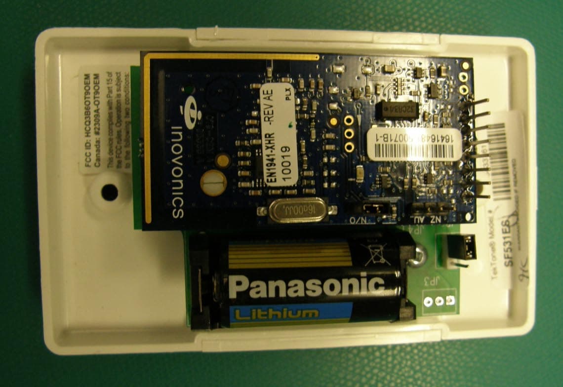
Click to zoom
Application Details
- Equipment Class
- DSS - Part 15 Spread Spectrum Transmitter
- Date of Grant
- Mar 14, 2011
- Application Purpose
- Original Equipment
- Date of Application
- Mar 14, 2011
- Equipment Note
- EchoStream (ES) System
- Frequency Range
- 902.40000000 - 927.60000000
- Country
- United States
Documents & Files
Document Text
Text extracted from the exhibit documents filed with the FCC. Open a document above to read the original.
Users Manual
© Inovonics, 2011 - www.inovonics.com One-Way Binary RF Module Installation and Operation Manual - 06287A 1 Overview EchoStream RF modules are designed to be easily interfaced with your electronic remote application controller (RAC). RF modules allow the assimilation of any user- specific application into an EchoStream system. Once integrated with existing products, RF modules provide you with complete EchoStream functionality. E*1941 one-way binary RF modules are end-devices that use a logic-level connection to interface with your RAC. E*1941 one-way binary RF modules can be used in either one-way or two-way EchoStream systems. Figure 1 One-Way System Components 2 One-Way Binary RF Module Components The E*1941 is a universal one-way binary RF module with two alarm input pins, allowing the use of dual inputs. Input one is the primary alarm, bit 0; input two is the secondary alarm, bit 1. There are two models in the E*1941 product family. • The EN1941, for 900 MHz applications in North America, New Zealand, and Australia, • The EE1941, for 868 MHz applications in Europe Figure 2 EN1941 One-Way Binary RF Module Components Figure 3 EE1941 One-Way Binary RF Module Components Frequency band selection pins (EN1941 only) Place a jumper to select the frequency band for your geographic area. • Place the jumper on the left two pins to select 915-928 MHz for Australia. • Place the jumper on the right two pins to select 921-928 MHz for New Zealand. • Leave the jumper off the pins to select 902-928 MHz for North America. ES selection pins (EE1941 only) To enable compatibility with ES products, place a selection jumper on the ES selection pins; if no ES products are used in your system, remove the selection jumper. N/O selection pins Place a jumper to select normally open inputs; remove the jumper to select normally closed. Note: The E*1941 is shipped with the jumper unattached. With the jumper unattached, the E*1941 defaults to normally closed. Secondary alarm Connects a secondary end-device to provide RF alarm data for any user-specific application. Primary alarm Connects a primary end-device to provide RF alarm data for any user- specific application. Tamper input Connects a tamper input to send a message when user-specific end- device is tampered with. Reset input Connects a reset input to reset the one-way binary RF module after a frequency band selection change or N/O - N/C selection change, and to initiate an RF transmission. Power Connect power cabling to an external power supply of 2.4 to 5.5 volts. Ground Connects to ground. Mounting hole Used to mount the one-way binary RF module to the user-specific product. The mounting hole should only be used with a nylon standoff, never metal. LED contacts Use to control an LED switch. Not designed to drive LED power. See “LED Requirements” on page 12 for information on using LED contacts. Board stabilization holes Used to mount and stabilize the board. The board stabilization holes should only be used with non-metal standoffs. 3 One-Way Binary RF Module Dimensions Figure 4 E*1941 One-Way Binary RF Module Dimensions A Board stabilization hole.BReservedCReserved DSecondary alarmEPowerFGround GPrimary alarmHLED contactsITamper input JReset inputKFrequency band selection pins LN/O selection pins MMounting holeNOn-board antennaOBoard stabilization hole ABoard stabilization hole. B ReservedCReserved DSecondary alarmEPowerFGround GPrimary alarmHLED contactsITamper input B C G D I J E F K L M N H A O B C G D I J E F K L M N H A O JReset inputKES selection pinsLN/O selection pins MMounting holeNOn-board antennaOBoard stabilization hole 1.3” Pitch: 2.54mm. .385” to Center of First Pin .090” to Center of First Pin .335” to Center of Hole .515” to Center of Hole .156” Radius .5” 2.525” © Inovonics, 2011 - www.inovonics.com 2 4 One-Way Binary RF Module Connections and Output Jumpers 5 Installation AConnecting the One-Way Binary RF Module BOne-way binary RF modules are designed to be easily interfaced with your electronic remote application controller, however integration must conform to the following: CThe RF module must only be connected at the eight pin header or eight pin plated thru-holes. DAll cables and wires must be routed away from the component side of the RF module. EThe integrated antenna must not be tampered with; no connection to an alternate antenna is provided. FThe application module must not include an integrated secondary colocated radio module. GThe one-way binary RF module antenna should be placed so that it is facing away, or otherwise isolated from, your device’s ground plane. HComponents that are sensitive to RF transmission, such as high gain circuits, should be isolated from the antenna to prevent interference. IOne-way binary RF modules should not be mounted on metal surfaces or inside metal enclosures. They should also not be mounted where sheet metal ductwork, wire mesh screens, etc. might block transmissions. JThe RF module should be integrated so the antenna is unobstructed by the end user’s PCB, batteries, or any other conductive material. Figure 5 The RF module should be integrated so the antenna is unobstructed 6 One-Way Binary RF Module Requirements 6.1 Power Requirements The E*1941 has an on-board voltage regulator. Connect power cabling to an external power supply (Vcc) of 2.4 to 5.5 volts. Voltage must be sustained at 2.4 volts or above and supply 100 milliamps during the transmit cycle. 6.2 EN1941 Assuming check-in messages every 3 minutes and infrequent alarm messages (one per day, on average), the average current draw is 32 uA. Peak current draw while transmitting is less than 100 mA. One alarm/restore cycle per hour results in about 5.3 uA increase in average current. 6.3 EE1941 Assuming check-in messages every 12 minutes and infrequent alarm messages (one per day, on average), the average current draw is 15 uA. Peak current draw while transmitting is less than 50 mA. One alarm/restore cycle per hour results in about 5.3 uA…
Text truncated - open the document above for the full version.
Attestation Statements
- ~9 -Inovonlcs February 28, 2011 Declaration of Similarity This is to certify that Inovonics products EN1941, EN1941-3600, EN1941-XHR and EN1941XS are all built on the same PC board and operate with the same core firmware. The only differences lie in binary data versus serial data, check in times and headers. The EN1941s are one-way binary data RF modules. The EN1941XS is a one-way serial data RF module. Floyd Nishi Director of Manufacturing Engineering
Cover Letter(s)
Authority to Act as Agent Date: March 7, 2011 American Certification Body, Inc. 6731 Whittier Avenue Suite C110 McLean, VA 22101 To Whom It May Concern: ______Keal Vigil ______ is authorized to act on our behalf, until otherwise notified, for applications to American Certification Body, Inc. (ACB). We certify that we are not subject to denial of federal benefits, that includes FCC benefits, pursuant to Section 5301 of the Anti-Drug Abuse Act of 1988, 21 U.S.C. 862. Further, no party, as defined in 47 CFR 1.2002 (b), to the application is subject to denial of federal benefits, that includes FCC benefits. Thank you, Agency Agreement Expiration Date: December 31, 2011 Keal Vigil Production Control Specialist II
Cover Letter(s)
Request for Confidentiality Date: March 9, 2011 Subject: Confidentiality Request for: FCC ID: HCQ3B6OT9OEM; IC ID 2309A-OTOEMM Pursuant to FCC 47 CRF 0.457(d) and 0.459 and IC RSP-100, Section 10, the applicant requests that a part of the subject FCC application be held confidential. Type of Confidentiality Requested Exhibit Short Term Permanent Block Diagrams Short Term External Photos Short Term Permanent* 1 Internal Photos Short Term Permanent Operation Description/Theory of Operation Short Term Permanent Parts List & Placement/BOM Short Term Permanent Tune-Up Procedure Short Term Permanent Schematics Short Term Test Setup Photos Short Term Permanent* User’s Manual *Note: ______(Insert Explanation as Necessary) ______ Inovonics Wireless Corporation has spent substantial effort in developing this product and it is one of the first of its kind in industry. Having the subject information easily available to "competition" would negate the advantage they have achieved by developing this product. Not protecting the details of the design will result in financial hardship. Permanent Confidentiality: The applicant requests the exhibits listed above as permanently confidential be permanently withheld from public review due to materials that contain trade secrets and proprietary information not customarily released to the public. Short-Term Confidentiality: The applicant requests the exhibits selected above as short term confidential be withheld from public view for a period of 180 2 days from the date of the Grant of Equipment Authorization and prior to marketing. This is to avoid premature release of sensitive information prior to marketing or release of the product to the public. Applicant is also aware that they are responsible to notify ACB in the event information regarding the product or the product is made available to the public. ACB will then release the documents listed above for public disclosure pursuant to FCC Public Notice DA 04-1705. 1 - The asterisked items (*) require further justification before permanent confidentiality will be allowed. These also currently require review by the FCC under their Permit-But-Ask policy before the grant is issued and can delay completion of an application. Further justification should be added to the note above. One such example for a potted device would be: “The EUT is FULLY potted using a non-removable epoxy based material. Removal of potting material causes irreparable damage to internal circuitry. See photographs exhibits that outline the device before and after potting.” 2 - Please refer to http://acbcert.com/documents/misc-docs/Memo-Short-Term-Vs-Standard-Confidentiality.pdf for complete details. NOTE for Industry Canada Applications: The applicant understands that until such time that IC distinguishes between Short Term and Permanent Confidentiality, either type of marked exhibit above will simply be marked Confidential when submitted to IC. Sincerely, Keal Vigil Production Control Specialist II
Cover Letter(s)
FCC Limited Modular Application Request FCC ID: HCQ3B6OT9OEM February 25, 2011 In compliance with FCC Public Notice DA 00-1407, this document is submitted to request a limited modular approval and address the eight requirements identified in the Public Notice: 1.) The RF portion of the circuit has limited shielding from the integrated ground plane in the device’s printed circuit board, and the requirement for shielding is not fully compliant for a full modular grant. Control of the final installation will be performed progressively through instructions documented in the installation manual, review of the host installation by Inovonics, and if necessary, testing the host installation to verify compliance. Additional information is submitted in Appendix A to demonstrate compliance when similar RF circuits are enclosed in a plastic case, which is typical of host installation enclosures. This is illustrated by photographs showing RF circuits that are identical in basic design with products that have already received grants and were tested while enclosed in plastic cases. 2.) This transmitter only accepts a switch closure for data input. The rate at which the input switches affect modulation is controlled by a micro-controller; excessive data rates are not possible. 3.) The modular transmitter has its own voltage regulator, VR1 on the schematic. 4.) The antenna on the modular transmitter is a printed trace on the PCB; it is permanently attached. 5.) The module was tested in a stand-alone configuration. Power was supplied by a 3.2 volt battery. 6.) The modular transmitter will be labeled with its own FCC ID number (see submitted picture), and the modular transmitters will include the following instructions for exterior label requirements: “FCC Label Requirements for EN1941 Inovonics Wireless has received Federal Communications Commission (FCC) approval to market RF modules. The host integrator is responsible for properly labeling the product containing the RF module. Labels must be placed on the outside of the product, and must include a statement indicating that product contains the module, along with the FCC number. Example 1 “Contains RF Module FCC ID: HCQ3B6OT9OEM” Example 2 “Contains FCC ID: HCQ3B6OT9OEM” RF Module FCC Registration Number EN1941 • FCC: HCQ3B6OT9OEM” 7.) The modular transmitter was tested and conforms with Section15.247. 8.) RF Exposure Information: The device is compliant with MPE requirements (47CFR2.1091) and SAR requirements (47CFR2.1093). Calculation for compliance with MPE requirements (47CFR2.1091) is done using a worst-case transmitter power of 50 mW, assuming a unity gain antenna, and an exposure limit of 0.6 mW/cm 2 (f/1500 mW/cm 2 at 20 cm per 47CFR1.1310) for general applications. This device is not carried or worn by the user. It has an extremely low duty cycle and a low rate of transmission that dramatically reduces the average power level that could pose an exposure hazard. The transmitter initiates a transmission upon sensing a change of state. In addition to these change-of-state transmissions, the transmitter is configured to transmit a supervisory message once every 3 minutes. The maximum message length may occur when the transmitter transmits a serial message consisting of a 12 ms preamble followed by 32 ms of synchronization, identification, payload, and CRC data. The averaging interval specified in Table 1(B) of 47CFR1.1310 is 30 minutes. For the purposes of this calculation, it is assumed that ten supervisory and five change-of-state messages will be sent in the 30-minute interval. Each supervisory message consists of 3 redundant packets, and each change of state message contains 21 packets, for a total of 135 packets in the 30-minute interval. A packet is typically 22.4 ms in length. For this calculation, a maximum packet length of 44 ms will be used. The worst-case average power density at a distance of 20 cm is then, 223 8.32 )20(4 1 1060 min144 min30 135 50 cm nW cmms packet mspackets mW=× × ××× π This is well below the 0.6 mW/cm 2 MPE limit. Calculation for compliance with SAR requirements (47CFR2.1093) is done using a worst-case transmitter power of 50 mW time-averaged by the duty cycle of the transmitter, and the assumption that all RF energy could be absorbed in 1 gram of tissue. The peak exposure limit is 1.6 mW/g (equivalent to 1.6 W/kg per 47CFR2.1093) in any 1 gram of tissue for General Population/Uncontrolled applications. In any 3-minute interval, worst-case the device may transmit up to 2 alarm messages and a supervisory message for a total of 45 packets. The maximum duty cycle of the device is, %1.1011.0 1060 min144 min3 45 3 == × ×× ms packet ms packets The time-averaged RF transmitted power is then, mWW55.0011.005.0=× If all of the transmitted power were absorbed in a 1-gram sample of tissue, the resulting power density is 0.55 mW/gram and is well below the 1.6 mW/gram limit. Sincerely, Floyd Nishi Manufacturing Engineering Manager APPENDIX A The following information is provided to demonstrate compliance when the transmitter is enclosed in a plastic case. The following is an example of a typical host installation. The radio module is shown attached on top of the host pc board. Emissions testing was performed on the radio module without being enclosed in a plastic case. The following photographs are submitted to demonstrate that the module’s radio circuits are identical in basic design with products that have already received grants and were tested while enclosed in plastic cases. EN1941 Module – HCQ3B6OT9OEM EN1249 BillTrap Alarm –HCQ3B6OT9BTX (date of grant: 12/23/08) EN1721 Temperature Sensor – HCQ3B6OT9THM (date of grant: 12/16/10) EN1242 Smoke Detector – HCQ3B6OT9ESL (date of grant: 12/10/10) Similarity of the Module’s Radio Circuit with Existing Grants using Plastic Enclosures
External Photos
FCC ID: HCQ3B6OT9EOM EN1941 Industry Canada ID: 2309A-OT9OEM External photos: External Front Back
ID Label/Location Info
CONFIDENTIAL DOCUMENT LBL-FCC-EN1941 05403C CONFIDENTIAL DOCUMENTATION The information contained in this document is confidential to and the sole property of Inovonics Corporation. Receipt of this information requires the existence and full acceptance of the terms and conditions of a Non Disclosure Agreement signed by the Inovonics Corporation and the Recipient. This documentation is not to be reproduced or redistributed except as provided in the Non Disclosure Agreement. MATERIAL:.002" THICK WHITE MYLAR WITH .001" MATTE LAMINATION (FOR PROTECTION FROM INK SMEARING) AND PERMANENT ADHESIVE APPLIED TO THE BACKSIDE. RoHS COM- PLIANT MATERIALS REQUIRED. ARTWORK:SUPPLIED BY INOVONICS TEXT: BLACK LABEL SIZE: 1.220" X .0.455" (SHOWN TO 3 TIMES SCALE), “SHARP CORNERS” AND NO BOR- DER PACKAGING AND LABEL ORIENTATION:LABELS TO BE SUPPLIED ON TOP SIDE OF ROLL STOCK WITH TEXT READABLE AS VIEWED FROM BOTTOM (SHORT) EDGE OF ROLL Rev. Level DescriptionDate AInitial Release10/17/2008 BEdited IC number07/07/2010 CAdded colon to FCC number03/09/2011 Confidential to Inovonics www.inovonics.com FCC ID: HCQ3B6OT9OEM / IC: 2309A-ETOEMM EN1941
Internal Photos
FCC ID: HCQ3B6OT9OEM EN1941, EN1941XS IC ID: 2309A-ETOEMM Page 1 Internal Photos: PCB Front Internal Photos (cont’d): PCB Back
RF Exposure Info
FCC ID: HCQ3B6OT9OEMEN1941 IC ID: 2309A-ETOEMM 9. RF Exposure Information: Calculation for compliance with MPE requirements (47CFR2.1091) is done using a worst-case transmitter power of 250 mW, assumption of a unity gain antenna, and an exposure limit of 0.6 mW/cm 2 (f/1500 mW/cm 2 at 20 cm per 47CFR1.1310 ) for general applications. This device is not carried or worn by the end user. It has an extremely low duty cycle and a low rate of transmission that dramatically reduces the average power level that could pose an exposure hazard. The transmitter is typically activated by the opening or closing of a door or window. In addition to these change-of-state transmissions, the transmitter is configured to transmit a supervisory message once every 3 minutes. The averaging interval specified in Table 1(B) of 47CFR1.1310 is 30 minutes. For the purposes of this calculation, it is assumed that ten supervisory and five change-of- state messages will be sent in the 30-minute interval. Each supervisory message consists of 3 redundant packets, and each change of state message contains 21 packets, for a total of 135 packets in the 30-minute interval. A packet is typically 20 ms in length. The worst-case power density at a distance of 20 cm is then, 223 6.74 )20(4 1 1060 min 120 min30 135 250 cm nW cmms packet mspackets mW=¥ ¥ ¥¥¥ p This is well below the 0.6 mW/cm 2 limit.
Test Report
This report is for the exclusive use of Intertek's Client and is provided pursuant to the agreement between Intertek and its Client. Intertek's responsibility and liability are limited to the terms and conditions of the agreement. Intertek assumes no liability to any party, other than to the Client in accordance with the agreement, for any loss, expense or damage occasioned by the use of this report. Only the Client is authorized to permit copying or distribution of this report and then only in its entirety. Any use of the Intertek name or one of its marks for the sale or advertisement of the tested material, product or service must first be approved in writing by Intertek. The observations and test results in this report are relevant only to the sample tested. This report by itself does not imply that the material, product, or service is or has ever been under an Intertek certification program. EMC Report for Inovonics on the EN1941 Page 1 of 24 TEST REPORT Report Number: 100356542DEN-001A Project Number: G100356542 Report Issue Date: 03/14/2011 Product Designation: EN1941 Standards: FCC title 47 CFR part 15 subpart C RSS-210:2010 Issue 8 AS/NZS 4268:2008 Tested by: Client: Intertek Testing Services NA, Inc. 1795 Dogwood St. Suite 200 Louisville, CO 80027 Inovonics Wireless Corp. 315 CTC Blvd. Louisville, CO 80027 Report prepared by Report reviewed by Randall Thompson Senior EMC Project Engineer Michael Spataro Engineering Team Leader Intertek Report Number: 100356542DEN-001A Issued: 03/14/2011 EMC Report for Inovonics on the EN1941 Page 2 of 24 TABLE OF CONTENTS 1 Introduction and Conclusion .............................................................................................................. 3 2 Test Summary ...................................................................................................................................... 3 3 Description of Equipment Under Test................................................................................................ 4 4 System setup including cable interconnection details, support equipment and simplified block diagram ........................................................................................................................................................ 5 5 Radiated Emissions – Intentional Radiators: Output Power - Fundamental & Harmonics of the Fundamental ................................................................................................................................................ 7 6 Radiated Emissions Unintentional & Spurious............................................................................... 13 7 Measurement Uncertainty ................................................................................................................. 23 8 Revision History................................................................................................................................. 24 Intertek Report Number: 100356542DEN-001A Issued: 03/14/2011 EMC Report for Inovonics on the EN1941 Page 3 of 24 1 Introduction and Conclusion The tests indicated in section 2.0 were performed on the product constructed as described in section 3.0. The remaining test sections are the verbatim text from the actual data sheets used during the investigation. These test sections include the test name, the specified test Method, a list of the actual Test Equipment Used, documentation Photos, Results and raw Data. No additions, deviations, or exclusions have been made from the standard(s) unless specifically noted. Based on the results of our investigation, we have concluded the product tested Passed with the requirements of the standard(s) indicated. The results obtained in this test report pertain only to the item(s) tested. 2 Test Summary Section Test full name Test date Result 5 Radiated Emissions – Output power of the Fundamental & Harmonics of the Fundamental - FCC 247(b)(2) (d)/15.205 Covers RSS-210 A8.4(1) 9/10/2008 Pass 6 Radiated Emissions – Unintentional & Spurious - FCC 15.247(d) / FCC 15.209/109 Covers RSS-210 A8.5 9/10/2008 Pass Bandwidth – FCC 15.247 (a)(2) ----- N/A Power Spectral Density (PSD) – FCC 15.247(e) ----- N/A Band Edge Measurements – FCC 15.247(d) / 15.209 ----- N/A Duty Cycle & Duty Cycle Correction Factor ----- N/A AC Conducted Emissions – FCC 15.207 – Not Applicable ----- N/A Notes: 1) Only the fundamental, harmonics of the fundamental and Spurious emissions are covered in this test report as requested by the customer. 2) Only the high channel of the transmitter at 927.58 MHz falls within the frequency band specified in AS/NZS 4268:2008 3) FCC CFR47 Part 15.31: Measurement Standards: In any case where the device is powered off a battery, a fresh battery was used during test. In cases where the device is powered off an AC supply, voltage was varied per Part 15.31 to find worst case emissions. Intertek Report Number: 100356542DEN-001A Issued: 03/14/2011 EMC Report for Inovonics on the EN1941 Page 4 of 24 3 Description of Equipment Under Test Equipment Under Test Description Manufacturer Model Number Serial Number 902-928MHz wireless transmitter. Inovonics EN1941 3879319 Receive Date: 09/10/2008 Received Condition: Good Type: Production Description of Equipment Under Test (provided by client) The Inovonics dual input one way RF module provides reliable low-cost, low-power wireless communications for integrators. Makes virtually any binary switch device wireless by integrating with the RF module. The dual input one way RF module is powered by the input device. The dual input one way RF module is available in two configurations. Use part number EE1941 for 868- 870 Mhz Europe; use part number EN1941 for 902-928 Mhz North America, 915-928 Mhz Australia, and 922-928 Mhz New Zealand. Equipment Under Test Power Configuration Rated Voltage Rated Current Rated Frequency Number of Phases 3.3 VDC - Battery ----------- ------------- ------------- Operating modes of the EUT: No. Descr…
Text truncated - open the document above for the full version.
Test Report
Rev. LevelDate A 25-Feb-11 IC ID: 2309A-ETOEMM Test report EN1941 CONFIDENTIAL DOCUMENTATION The information contained in this document is confidential to and the sole property of Inovonics Wireless Corporation. Receipt of this information requires the existence and full acceptance of the terms and conditions of a Non-Disclosure Agreement signed by Inovonics Wireless Corporation and the Recipient. This documentation is not to be reproduced or redistributed, except as provided in the Non-Disclosure Agreement. DescriptionAuthor Initial Release HB FCC ID: HCQ3B6ETOEMM Pass/FailPage N/A 1 Pass 2 Pass 3 Pass 4 Pass 5 Pass 6 Continuous receiver operationN/A Min Channel Seperation Continuous transmitter operation 20 dB Occupied BW Dwell Time # of hopping Channels Instrument declarations No Section 1 Section 2 Section 3 Section 4 Section 5 General Test Report Band of operation (USA)902-928 MHz Additional Information Declarations Table of contents 921.6 MHz Yes 22msMaximum TX on-time (single message) 915-928 MHz 400KHz Yes Normal battery input voltage N/A 3V DC Band of operation (Australia mode) Band of operation (New Zealand mode)921-928 MHz Frequency hopping transmitter Lower transmit frequency (New Zealand) Integral antenna equipment 927.6 MHz Receiver frequencies Upper transmit frequency (AUS and NZ) Minimum Transmit Channel Spacing Lower transmit frequency (Australia)915.6 MHz Band of operation (USA)902 928 MHz Section 25-Feb-11 25.93 C 31.63% N/A Test Report Additional Information Test Method 15.247 UUT Model No.EN1941Test Date UUT Serial Number(s)Normal Temp UUT DescriptionSecurity transmitterNormal Humidity UUT MFGR:Inovonics Wireless TEST NOTES Tested By:HBTest Result Test Report Additional Information In addition to the intentional and unintentional emissions lab test reports submitted with this application, additional test data demonstrating compliance with CFR47, 15.247 and RSS-210, A8.1 follows. For the following measurements, the antenna was replaced by a coaxial connection to a MXA N9020A spectrum analyzer. Section 25-Feb-11 25.93 C 31.63% Pass Minimum Channnel Seperation Test Method 15.247 UUT Model No.EN1941Test Date UUT Serial Number(s)Normal Temp UUT DescriptionSecurity transmitterNormal Humidity UUT MFGR:Inovonics Wireless TEST NOTES Tested By:HBTest Result Minimum Channel Separation: Plot 1 is a spectrum plot showing a minimum channel separation of 800 kHz. Compliance with CFR47, 15.247(a)(1), and RSS-210, A8.1(b) is demonstrated by capturing several transmissions over a small portion of the 902-928 MHz ISM band. Measured Ch seperation in KHzComplies 800Yes Plot 1: Demonstration of channel spacing requirement. Section 25-Feb-11 25.93 C 31.63% Pass 20 dB occupied Bandwidth Test Method 15.247 UUT Model No.EN1941Test Date UUT Serial Number(s)Normal Temp UUT DescriptionSecurity transmitterNormal Humidity UUT MFGR:Inovonics Wireless TEST NOTES Tested By:HBTest Result 20 dB occupied bandwidth: Plot 2 shows the 20 dB occupied bandwidth of a single channel to demonstrate compliance with 15.247(a)(1)(i) and RSS-210, A8.1(c). The 20 dB occupied bandwidth is 268.5 kHz. ChannelMeasuredMaximum Frequency 20dB bandwidthlimit in MHzin KHzin KHzComplies 927.6283.82500Yes Plot 2: Occupied Bandwidth at lower frequency Section 25-Feb-11 25.93 C 31.63% PassTested By:HBTest Result Number of hopping Channels: Plot 3 demonstrates compliance with 15.247(a)(1)(i), and RSS-210, A8.1(c). This is a stored display of many sequential transmissions to show the overall band occupied by the transmitter. UUT MFGR:Inovonics Wireless TEST NOTES UUT Serial Number(s)Normal Temp UUT DescriptionSecurity transmitterNormal Humidity # of transmitter channels Test Method 15.247 UUT Model No.EN1941Test Date # of TXmin required channels# of channelsComplies 2520Yes Plot 3: Demonstration of 25 hopping channels. Section 25-Feb-11 25.93 C 31.63% Pass Dwell Time Test Method 15.247 UUT Model No.EN1941Test Date UUT Serial Number(s)Normal Temp UUT DescriptionSecurity transmitterNormal Humidity UUT MFGR:Inovonics Wireless TEST NOTES Tested By:HBTest Result Dwell Time: Plot 4 demonstrates compliance with 15.247(a)(1)(i), and RSS-210, A8.1(c), which states “the average time of occupancy on any channel shall not be greater than 0.4 seconds within a 10 second period.” Measuresd Maximum Dwell Timelimit in msin secondsCompliesComplies 21.430.4YesYes Plot 4: Demonstration of Frequency Dwell Time. Sections Description Make27-Sep-10 Model #27-Sep-11 Serial # TEST INSTRUMENTS Testing InstrumentSpectrum Analyzer/RF Power meter Signal Analyzer AgilentCalibration date N9020ACalibration due date MY46471353 Tested By:HB UUT MFGR:Inovonics Wireless TEST NOTES UUT Serial Number(s) UUT DescriptionSecurity transmitter Test Instrument Declarations Test Method 15.247 UUT Model No.EN1941 2, 3, 4 and 5 Alternative to Conducted Output Power Measurements: Required conducted power output measurements at low, medium, and high channels (per 15.247(b) and (c)) could not be performed directly since the transmit antenna is integrated onto the printed circuit board. However, compliance with these requirements has been achieved by way of performing and passing the radiated tests described in the ALTERNATIVE TEST PRO…
Text truncated - open the document above for the full version.
Contact Information
Applicant
Jess Cobb(Manager of Program Mgmt)
Technical Contact
Inovonics Wireless Corp.Daryl Burkhard
[email protected]303 209 7145
315 CTC Blvd. · Louisville · United States
Test Firm
Intertek Testing Services NA, Inc.Paul Coghill
Technical Specifications
| # | Rule Parts | Frequency Range | Power Output |
|---|---|---|---|
| 1 | 15C | 902.4 MHz - 927.6 MHz | 135.00 mW |
Other Applications from Inovonics Wireless Corporation

HCQ-IDTOUCH1
May 13, 2026Inovonics Wired Touchscreen Keypad
Equipment Class
DTS - Digital Transmission System
HCQBWA02
Aug 28, 2024Flush Mount Locator
Equipment Class
DSS - Part 15 Spread Spectrum Transmitter
HCQTBA
Sep 21, 2022TBA Module
Equipment Class
DSS - Part 15 Spread Spectrum Transmitter
HCQPFA01
Jul 14, 2022Fall Detect Transmitter
Equipment Class
DSS - Part 15 Spread Spectrum Transmitter
HCQ3B6BRGSA
Sep 22, 2020Bluetooth to EchoStream Bridge
Equipment Class
DTS - Digital Transmission System