HCQ3B6OT9UMXSingle Input Universal Transmitter
Inovonics Wireless Corporation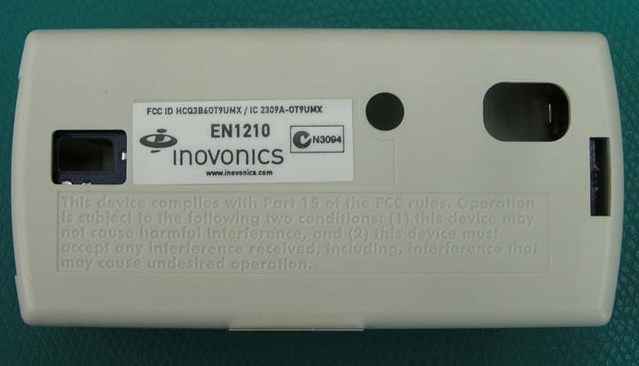
Click to zoom
Application Details
- Equipment Class
- DSS - Part 15 Spread Spectrum Transmitter
- Date of Grant
- Apr 05, 2011
- Application Purpose
- Original Equipment
- Date of Application
- Apr 05, 2011
- Equipment Note
- Single Input Universal Transmitter
- Frequency Range
- 902.38000000 - 927.59000000
- Country
- United States
Documents & Files
Document Text
Text extracted from the exhibit documents filed with the FCC. Open a document above to read the original.
Users Manual
© Inovonics, 2011 - www.inovonics.com EN1210 EchoStream® Single Input Universal TransmitterInstallation Instructions - 05177D1 OverviewThe EN1210 is a universal security transmitter.1.1 Inovonics Wireless Contact InformationIf you have any problems with this procedure, contact Inovonics Wireless technical services: • E-mail: [email protected]• Phone: (800) 782-2709 1.2 EN1210 Components Figure 1 EN1210 components 2 Installation and Startup2.1 Install/Replace the Battery 1. Pry the top lip of the mounting bracket up, and lift the bracket off of the transmitter. 2. Use your thumb to depress the housing release tab on the bottom of the transmitter; separate the housing. 3. If replacing a battery, use the hole in the back of the housing to push the old battery out of the battery holder. 4. Install the new battery. 5. Press the Reset button to initialize the transmitter. 2.2 Select the Frequency BandEchoStream products are able to use a range of radio frequencies, and must be configured for your geographic area. To configure the transmitter: 1. Place a selection jumper on the appropriate frequency band selection pins. • Place the jumper on the right two pins, marked NZ, to set the frequency range to 921-928 MHz for New Zealand. • Place the jumper on the left two pins, marked AU, to set the frequency range to 915-928 MHz for Australia. • Leave the jumper off the pins to set the frequency range to 902-928 MHz for North America. 2. Press the Reset button to complete configuration. Caution: When pressing the Reset button, make sure you don’t also touch the frequency band selection pins. Touching the frequency band selection pi ns while pressing the Reset button can inadvertently set the EN1210 to the wrong frequency band.3 Select Input TypeThe N/O-N/C selection pins allow the choice of a normally open or normally closed state for the c ontact circuit wired to the input terminal.The transmitter is shipped set for normally closed, with no selection jumper on the N/O selections pins. 1. Place a selection jumper on the selection pins to select normally open; remove the selection jumper from the selection pins to select normally closed. 2. Press the Reset button to complete configuration. 4 Register the EN1210Transmitters must be registered with the system in order to be monitored and supervised. Tr ansmitters send a check-in message every three minutes. Each transmitter has a unique factory-programmed identification number.Refer to the receiver installa tion instructions for details on registering a transmitter. 1. When prompted by the receiver to reset transmitter, press the Reset button. 2. Replace the cover. 3. Test the EN1210 by activating each of the conditions and ensuring an appropriate response. 4.1 Mount the EN1210 1. Mount the bracket on the wall with the screws provided. 2. Clip the transmitter onto the bracket. Hook the bottom catch first, then press the top into place. 3. The housing may be secured with a third mounting screw, located beneath the battery. Note: Accessing this screw on an active transmitter requires opening the housing and removing the battery, causing a tamper condition.4. To dismount the EN1210, pull the transmitter housing carefully out of the mounting bracket from the top. 5 SpecificationsExternal contacts: NO or NC Distance, external contact to EN1210: 3 meters (10 feet) maximumTypical battery life: 3-5 years Battery type (BAT604): Panasonic CR123A or equivalent Operating environment: -20° to 60°C (-4° to 140°F), noncondensingNote: Specifications and data are subject to change without notice. 6 Television and Radio InterferenceThis equipment has been tested and found to comply with the limits for a Class B digital device, pursuant to Part 15 of the FCC Rules. These limits are designed to provide reasonable protection against harmful interference in a residential installation. This equipment generates, uses and can radiate radio frequency energy and, if not installed and used in accordance with the instructions, may cause harmful interference to radio communications. However, there is no guarantee that interference will not occur in a particular installation. If this equipment does cause harmful interference to radio or television reception, which can be determined by turning the equipment off and on, the user is encouraged to try to correct the interference by one or more of the following measures: • Reorient or relocate the receiving antenna.• Increase the separation between the equipment and receiver. • Connect the equipment into an outlet on a circuit different from that to which the receiver is connected. • Consult the dealer or an experienced radio/TV technician for help. 7 FCC Part 15 ComplianceThis device complies with part 15 of the FCC Rules. Operation is subject to the following two conditions: 1. This device may not cause harmful interference, and 2. this device must accept any in terference received, including interference that may cause undesired operation. 8 Warranty and DisclaimerNote: Changes or modifications not expressly approved by the party responsible for compliance c ould void the user's authority to operate the equipment.Inovonics Wireless Corporati on ("Inovonics") warrants its products ("Product" or "Products") to conform to its own specifications and to be free of defects in materials and workmanship under normal use for a period of twenty-four (24) months from the date of manufacture. Within the warranty period, Inovonics will repair or r eplace, at its option, all or any part of the warranted Product. Inovonics will not be responsible for dismantling and/or reinstallation charges. To exercise the warranty, the User ("User", "Installer" or "Consumer") must work directly through their authorized distributor who will be given a Return Material Authorization ("RMA") number by Inovonics. Details of shipment will be arranged directly through the authorized distributor.This warranty is void in cases of improper installation, misuse, failure t…
Text truncated - open the document above for the full version.
Cover Letter(s)
Request for Confidentiality Date: March 24, 2011 Subject: Confidentiality Request for: FCC ID: HCQ3B6OT9UMX; IC ID 2309A-OT9UMX Pursuant to FCC 47 CRF 0.457(d) and 0.459 and IC RSP-100, Section 10, the applicant requests that a part of the subject FCC application be held confidential. Type of Confidentiality Requested Exhibit Short Term Permanent Block Diagrams Short Term External Photos Short Term Permanent* 1 Internal Photos Short Term Permanent Operation Description/Theory of Operation Short Term Permanent Parts List & Placement/BOM Short Term Permanent Tune-Up Procedure Short Term Permanent Schematics Short Term Test Setup Photos Short Term Permanent* User’s Manual *Note: ______(Insert Explanation as Necessary) ______ Inovonics Wireless Corporation has spent substantial effort in developing this product and it is one of the first of its kind in industry. Having the subject information easily available to "competition" would negate the advantage they have achieved by developing this product. Not protecting the details of the design will result in financial hardship. Permanent Confidentiality: The applicant requests the exhibits listed above as permanently confidential be permanently withheld from public review due to materials that contain trade secrets and proprietary information not customarily released to the public. Short-Term Confidentiality: The applicant requests the exhibits selected above as short term confidential be withheld from public view for a period of 180 2 days from the date of the Grant of Equipment Authorization and prior to marketing. This is to avoid premature release of sensitive information prior to marketing or release of the product to the public. Applicant is also aware that they are responsible to notify ACB in the event information regarding the product or the product is made available to the public. ACB will then release the documents listed above for public disclosure pursuant to FCC Public Notice DA 04-1705. 1 - The asterisked items (*) require further justification before permanent confidentiality will be allowed. These also currently require review by the FCC under their Permit-But-Ask policy before the grant is issued and can delay completion of an application. Further justification should be added to the note above. One such example for a potted device would be: “The EUT is FULLY potted using a non-removable epoxy based material. Removal of potting material causes irreparable damage to internal circuitry. See photographs exhibits that outline the device before and after potting.” 2 - Please refer to http://acbcert.com/documents/misc-docs/Memo-Short-Term-Vs-Standard-Confidentiality.pdf for complete details. NOTE for Industry Canada Applications: The applicant understands that until such time that IC distinguishes between Short Term and Permanent Confidentiality, either type of marked exhibit above will simply be marked Confidential when submitted to IC. Sincerely, Keal Vigil Production Control Specialist II
Cover Letter(s)
Authority to Act as Agent Date: March 8, 2011 American Certification Body, Inc. 6731 Whittier Avenue Suite C110 McLean, VA 22101 To Whom It May Concern: ______Keal Vigil______ is authorized to act on our behalf, until otherwise notified, for applications to American Certification Body, Inc. (ACB). We certify that we are not subject to denial of federal benefits, that includes FCC benefits, pursuant to Section 5301 of the Anti-Drug Abuse Act of 1988, 21 U.S.C. 862. Further, no party, as defined in 47 CFR 1.2002 (b), to the application is subject to denial of federal benefits, that includes FCC benefits. Thank you, Agency Agreement Expiration Date: December 31, 2011 Keal Vigil Production Control Specialist II
External Photos
FCC ID: HCQ3B6OT9UMX EN1210 IC ID: 2309A-OT9UMX External Photos: Front of product Back of product showing FCC & IC ID Number . Page 1
ID Label/Location Info
LBL-FCC-EN1210 05197C MATERIAL:.002" THICK WHITE MYLAR WITH .001" MATTE LAMINATION (FOR PROTECTION FROM INK SMEARING) AND PERMANENT ADHESIVE APPLIED TO THE BACKSIDE. RoHS COM- PLIANT MATERIALS REQUIRED. ARTWORK:SUPPLIED BY INOVONICS TEXT: BLACK LABEL SIZE: 1.220" X .0.455" (SHOWN TO 3 TIMES SCALE), “SHARP CORNERS” AND NO BOR- DER PACKAGING AND LABEL ORIENTATION:LABELS TO BE SUPPLIED ON TOP SIDE OF ROLL STOCK WITH TEXT READABLE AS VIEWED FROM BOTTOM (SHORT) EDGE OF ROLL Rev. Level DescriptionDate AInitial Release01/18/2008 BUpdated for EchoStream Optimization05/29/2008 CAdd colon per FCC03/17/2011 w w w.inovonics.com FCC ID: HCQ3B6OT9UMX / IC: 2309A-OT9UMX EN1210
Internal Photos
FCC ID: HCQ3B6OT9UMX EN1210 IC ID: 2309A-OT9UMX Internal Photos: Trace Antenna PCB FRONT PCB BACK Page 1
RF Exposure Info
FCC ID: HCQ3B6OT9UMX EN1210 IC ID: 2309A-OT9UMX RF Exposure Information: Calculation for compliance with MPE requirements (47CFR2.1091) is done using a worst-case transmitter power of 250 mW, assumption of a unity gain antenna, and an exposure limit of 0.6 mW/cm 2 (f/1500 mW/cm 2 at 20 cm per 4 7CFR1.1310) for general applications. This device is not carried or worn by the end user. It has an extremely low duty cycle and a low rate of transmission that dramatically reduces the average power level that could pose an exposure hazard. The transmitter is typically activated by the opening or closing of a door or window. In addition to these change-of-state transmissions, the transmitter is configured to transmit a supervisory message once every 3 minutes. The averaging interval specified in Table 1(B) of 47CFR1.1310 is 30 minutes. For the purposes of this calculation, it is assumed that ten supervisory and five change-of- state messages will be sent in the 30-minute interval. Each supervisory message consists of 3 redundant packets, and each change of state message contains 21 packets, for a total of 135 packets in the 30-minute interval. A packet is typically 20 ms in length. The worst-case power density at a distance of 20 cm is then, 223 6.74 ) 20(4 1 1060 min120 min30 135 250 cm nW cmms packet mspackets mW=¥ ¥ ¥¥¥ p This is well below the 0.6 mW/cm 2 limit.
Test Report
This report is for the exclusive use of Intertek's Client and is provided pursuant to the agreement between Intertek and its Client. Intertek's responsibility and liability are limited to the terms and conditions of the agreement. Intertek assumes no liability to any party, other than to the Client in accordance with the agreement, for any loss, expense or damage occasioned by the use of this report. Only the Client is authorized to permit copying or distribution of this report and then only in its entirety. Any use of the Intertek name or one of its marks for the sale or advertisement of the tested material, product or service must first be approved in writing by Intertek. The observations and test results in this report are relevant only to the sample tested. This report by itself does not imply that the material, product, or service is or has ever been under an Intertek certification program. EMC Report for Inovonics on the EN1210 Page 1 of 21 TEST REPORT Report Number: 100356542DEN-002A Project Number: G100356542 Report Issue Date: 03/23/2011 Product Designation: EN1210 Standards: FCC title 47 CFR part 15 subpart C RSS-210:2010 Issue 8 AS/NZS 4268:2008 Tested by: Client: Intertek Testing Services NA, Inc. 1795 Dogwood St. Suite 200 Louisville, CO 80027 Inovonics Wireless Corp. 315 CTC Blvd. Louisville, CO 80027 Report prepared by Report reviewed by Randall Thompson Senior EMC Project Engineer Michael Spataro Engineering Team Leader Intertek Report Number: 100356542DEN-002A Issued: 03/23/2011 EMC Report for Inovonics on the EN1210 Page 2 of 21 TABLE OF CONTENTS 1 Introduction and Conclusion .............................................................................................................. 3 2 Test Summary ...................................................................................................................................... 3 3 Description of Equipment Under Test................................................................................................ 4 4 System setup including cable interconnection details, support equipment and simplified block diagram ........................................................................................................................................................ 5 5 Radiated Emissions – Intentional Radiators: Output Power - Fundamental & Harmonics of the Fundamental for 15.247 .............................................................................................................................. 7 6 Radiated Emissions Unintentional & Spurious............................................................................... 12 7 Measurement Uncertainty ................................................................................................................. 20 8 Revision History................................................................................................................................. 21 Intertek Report Number: 100356542DEN-002A Issued: 03/23/2011 EMC Report for Inovonics on the EN1210 Page 3 of 21 1 Introduction and Conclusion The tests indicated in section 2.0 were performed on the product constructed as described in section 3.0. The remaining test sections are the verbatim text from the actual data sheets used during the investigation. These test sections include the test name, the specified test Method, a list of the actual Test Equipment Used, documentation Photos, Results and raw Data. No additions, deviations, or exclusions have been made from the standard(s) unless specifically noted. Based on the results of our investigation, we have concluded the product tested Passed with the requirements of the standard(s) indicated. The results obtained in this test report pertain only to the item(s) tested. 2 Test Summary Section Test full name Test date Result 5 Radiated Emissions – Output power of the Fundamental & Harmonics of the Fundamental - FCC 247(b)(2) (d)/15.205 Covers RSS-210 A8.4(1) 5/1/2008 Pass 6 Radiated Emissions – Unintentional & Spurious - FCC 15.247(d) / FCC 15.209/109 Covers RSS-210 A8.5 3/14/2011 Pass 20dB Bandwidth – FCC 15.247 (a)(1)(i) [Covers RSS-210, A8.1(c)] ----- N/A Number of Hopping Channels – FCC 15.247(a)(1)(i) [Covers RSS-210, A8.1(c)] ----- N/A Hopping Channel Carrier Separation – FCC 15.247(a)(1) [Covers RSS-210, A8.1(b)] ----- N/A Band Edge Measurements – FCC 15.247(d) / 15.209 [Covers RSS-210, A8.5] ----- N/A Duty Cycle & Duty Cycle Correction Factor ----- N/A AC Conducted Emissions – FCC 15.207 (not applicable – product battery-powered) ----- N/A Notes: 1) Only the fundamental, harmonics of the fundamental and Spurious emissions are covered in this test report as requested by the customer. 2) Only the high channel of the transmitter at 927.59 MHz falls within the frequency band specified in AS/NZS 4268:2008 3) FCC CFR47 Part 15.31: Measurement Standards: In any case where the device is powered off a battery, a fresh battery was used during test. In cases where the device is powered off an AC supply, voltage was varied per Part 15.31 to find worst case emissions. Intertek Report Number: 100356542DEN-002A Issued: 03/23/2011 EMC Report for Inovonics on the EN1210 Page 4 of 21 3 Description of Equipment Under Test Equipment Under Test Description Manufacturer Model Number Serial Number 902-928 MHz wireless transmitter. Inovonics EN1210 03609694/90155045 Receive Date: 5/1/2008 Received Condition: Good Type: Production Description of Equipment Under Test (provided by client) The Inovonics universal transmitter is designed for use with almost any standard contact or sensor. The transmitter is fully supervised and includes a case and/or wall tamper that notifies systems when the transmitter is removed from its mounted surface or the case is opened. Models with a magnetic switch are typically used in security applications to detect the opening of doors and windows. The universal transmitter is available in several configurations that include single or dual …
Text truncated - open the document above for the full version.
Test Report
1 Test Report: Additional Information Model EN1210 Revision Description Author Issue Date A Initial Release HB 30-Mar-11 General Remarks: In addition to the intentional and unintentional emissions lab test reports submitted with this application, this test report includes additional test data demonstrating compliance with CFR47, 15.247 and RSS-210, A8.1. For the measurements in this report, the antenna was replaced by a coaxial connection to a MXA signal analyzer, model N9020A. Calculations for Conducted Output Power and Duty Cycle Correction Factor are also included. 2 Report Summary Result Page Section 1 Minimum Channel Separation Pass 3 Section 2 20 dB Occupied BW Pass 4 Section 3 Number of Hopping Channels Pass 5 Section 4 Dwell Time Pass 6 Section 5 Test Instrument Declarations Pass 7 Section 6 Conducted Output Power & Duty Cycle N/A 8 Correction Factor General Declarations Continuous receiver operation N/A Continuous transmitter operation No Band of operation (USA and Canada) 902-928 MHz Band of operation (Australia mode) 915-928 MHz Band of operation (New Zealand mode) 921-928 MHz Lower transmit frequency (Australia) 915.6 MHz Lower transmit frequency (New Zealand) 921.6 MHz Upper transmit frequency (AUS and NZ) 927.6 MHz Minimum Transmit Channel Spacing 400KHz Receiver frequencies N/A Frequency hopping transmitter Yes Integral antenna equipment Yes Normal battery input voltage 3V DC Maximum TX on-time (single message) 22ms 3 Minimum Channel Separation Test Method 15.247 Section 1 UUT Model No. EN1210 Test Date 30-Mar-11 UUT Serial Number(s) Normal Temp 25.93 C UUT Description Security transmitter Normal Humidity 31.63% UUT MFGR: Inovonics Wireless Tested By: HB Test Result Pass 4 20 dB Occupied Bandwidth Test Method 15.247 Section 2 UUT Model No. EN1210 Test Date 30-Mar-11 UUT Serial Number(s) Normal Temp 25.93 C UUT Description Security transmitter Normal Humidity 31.63% UUT MFGR: Inovonics Wireless Tested By: HB Test Result Pass Plot shows the 20 dB occupied bandwidth of a single channel to demonstrate compliance with 15.247(a)(1)(i) and RSS-210, A8.1(c). 5 Number of Transmitter Channels Test Method 15.247 Section 3 UUT Model No. EN1210 Test Date 30-Mar-11 UUT Serial Number(s) Normal Temp 25.93 C UUT Description Security transmitter Normal Humidity 31.63% UUT MFGR: Inovonics Wireless Tested By: HB Test Result Pass Plot demonstrates compliance with 15.247(a)(1)(i), and RSS-210, A8.1(c). This is a stored display of many sequential transmissions to show the overall band occupied by the transmitter. 6 Dwell Time Test Method 15.247 Section 4 UUT Model No. EN1210 Test Date 30-Mar-11 UUT Serial Number(s) Normal Temp 25.93 C UUT Description Security transmitter Normal Humidity 31.63% UUT MFGR: Inovonics Wireless Tested By: HB Test Result Pass Plot demonstrates compliance with 15.247(a)(1)(i), and RSS-210, A8.1(c), which states “the average time of occupancy on any channel shall not be greater than 0.4 seconds within a 10 second period.” Measured Dwell Time in ms Maximum limit in seconds Complies 21.44 0.4 Yes 7 Test Instrument Declarations Test Method 15.247 Section 1 through 4 UUT Model No. EN1210 UUT Serial Number(s) UUT Description Security transmitter UUT MFGR: Inovonics Wireless Testing Instrument Description Signal Analyzer Make Agilent Calibration date 27-Sep-10 Model # N9020A Calibration due date 27-Sep-11 Serial # MY46471353 8 Alternative to Conducted Output Power Measurements: Required conducted power output measurements at low, medium, and high channels (per 15.247(b) and (c)) could not be performed directly since the transmit antenna is integrated onto the printed circuit board. However, compliance with these requirements has been achieved by way of performing and passing the radiated tests described in the ALTERNATIVE TEST PROCEDURES in Public Notice DA 00-705, March 30, 2000. Specifically, all radiated emissions shown in the test report are less than 119.2 dBuV/m at 3 meters. This is the field strength limit corresponding to the maximum fundamental power output of 0.25 watts from an isotropic antenna per 15.247 (b) (2) for systems employing between 25 and 49 hopping channels. The calculation as detailed in the above Public Notice is as follows: E = Square Root of (30PG) all divided by d E = 912,871 uV/m = 119.21 dB uV/m where E is the maximum allowable fundamental field strength in uV/m P is the maximum allowable fundamental radiated power = 0.25 watts G is the antenna gain = 1 (Assume 1 for the worst case (lowest allowable) final field strength.) d is the measured distance = 3 meters Duty Cycle Correction Factor (DCCF) DCCF formula obtained from Public Notice DA 00-705 dBDCCF ms ms DCCF ms timeDwell DCCF 6.13 100 8.20 log20 100 log20
Test Setup Photos
Project File: 3153191 Page 5 of 19 Intertek ETL Semko 5541 Central Avenue, Suite 110 Boulder, Colorado 80301 Voice: 303 786 7999Fax: 303 449 6160 Rev.No 1 Test-setup photo(s): Intentional Radiated Emissions: Project File: 3153191 Page 6 of 19 Intertek ETL Semko 5541 Central Avenue, Suite 110 Boulder, Colorado 80301 Voice: 303 786 7999Fax: 303 449 6160 Rev.No 1 Test-setup photo(s): Intentional Radiated Emissions:
Contact Information
Applicant
Jess Cobb(Manager of Program Mgmt)
Test Firm
Intertek Testing Services NA, Inc.Paul Coghill
Technical Specifications
| # | Rule Parts | Frequency Range | Power Output |
|---|---|---|---|
| 1 | 15C | 902.38 MHz - 927.59 MHz | 43.00 mW |
Other Applications from Inovonics Wireless Corporation

HCQ-IDTOUCH1
May 13, 2026Inovonics Wired Touchscreen Keypad
Equipment Class
DTS - Digital Transmission System
HCQBWA02
Aug 28, 2024Flush Mount Locator
Equipment Class
DSS - Part 15 Spread Spectrum Transmitter
HCQTBA
Sep 21, 2022TBA Module
Equipment Class
DSS - Part 15 Spread Spectrum Transmitter
HCQPFA01
Jul 14, 2022Fall Detect Transmitter
Equipment Class
DSS - Part 15 Spread Spectrum Transmitter
HCQ3B6BRGSA
Sep 22, 2020Bluetooth to EchoStream Bridge
Equipment Class
DTS - Digital Transmission System