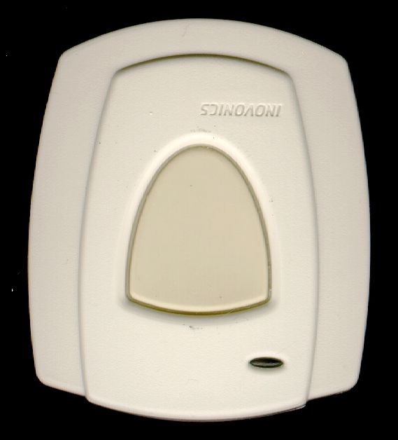
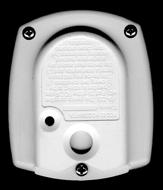
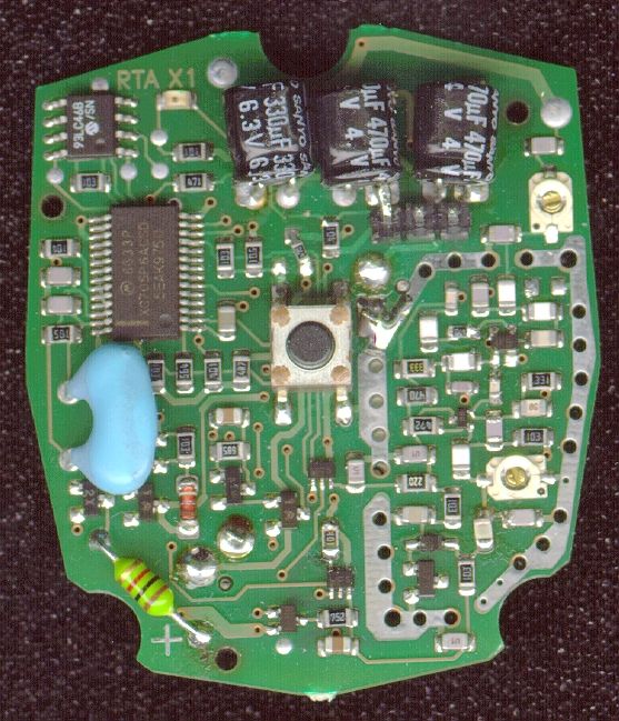
HCQ3B6RTARemote Pendant Transmitter
Inovonics Wireless Corporation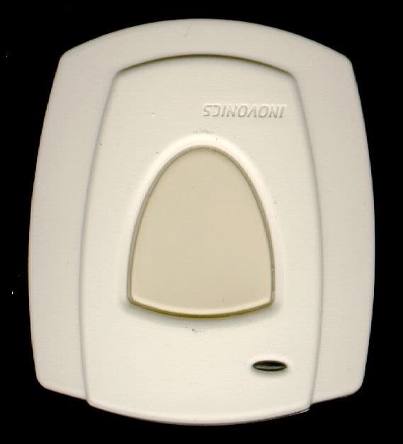
Click to zoom
Application Details
- Equipment Class
- DSS - Part 15 Spread Spectrum Transmitter
- Date of Grant
- Mar 07, 2000
- Application Purpose
- Original Equipment
- Date of Application
- Sep 29, 1999
- Equipment Note
- Remote Pendant Transmitter
- Frequency Range
- 906.00000000 - 920.00000000
- Country
- United States
Documents & Files
Document Text
Text extracted from the exhibit documents filed with the FCC. Open a document above to read the original.
Users Manual
© 1999 Inovonics [email protected]: 800.782.2709 www.inovonics.comf223_v1.fm rev 1.00 8/20/99 Intended use: The FA223S portable transmitter utilizes Inovon- ics 900MHz Frequency Agile ® technology. The transmitter, intended to be installed and serviced by licensed security profes- sionals, transmits messages to an Inovonics receiver. The FA223S has a water-resistant housing suitable for use in showers and bathtubs. It is not, however, designed for prolonged submersion, or for subermersion deeper than one foot. •To activate the FA223S, press and hold the Transmit Button for at least 1 second. (Actual minimum activation interval is .700 second.) •Alarm signals are transmitted multiple times, and are indicated by the blinking transmit LED. •Holding the button results in continuous transmission. •When the button is released, the FA223S will complete its alarm trans- mission, then will send an alarm restoral signal. Dimensions:2.22" x 1.925" x0.725" Weight:1.4 oz. External contacts:N/O Typical battery life:1 to 2 years Battery (BAT609):3.0V lithium Sanyo CR2450 —or— Renata CR2450N (The battery is always supervised.) 1. Open the transmitter housing by removing three phillips-head screws. 2. When prompted by the programming device to plug in the transmitter, connect the programming cable to the 3-pin programming header. 3. Press the internal reset button. 4. Disconnect the programming cable. 5. Re-assemble and thoroughly test the transmitter. NOTE: FA223S transmitters retain programming data in non-volatile mem- ory. They do not require reprogramming after loss of power. Install new bat- tery and press either the internal or the external reset button to re-initialize the transmitter and restore programming. IMPORTANT: The FA223S should always be programmed for supervision. II Inovonics recommends that pendants always be supervised. Pendants should also be tested at least once per week. Suggested check-in interval: 5 minutes External contacts:N/O II For information on supervision programming options, request TechNotes TN1025 and TN1032. The FA223S can be carried in 3 convienient ways: • Around the neck as a pendant (standard). • On a belt with the beltclip attachment (standard). • On the arm with optional wristband accessory (ACC634W). II Caution: Neck Cord Safety WARNING: The neck cord provided with the FA223S is designed for user safety. Substitution of stronger cords or chains may result in injury to the wearer. External Transmit LED Transmit Button Reset Button FA223S Single-button Pendant transmitter Operation Specifications Changing the battery: 1)Remove 3 screws from the back of the housing. 2)Make sure that the battery is inserted with the positive (+) ter- minal facing the indicated side of the holder. 3)After replacing the battery, press the internal reset button to reset the transmitter to its most recent programming. 4)Replace back cover and care- fully re-tighten screws evenly for tight seal 5) Thoroughly test the unit before returning to service. Internal Reset Button 3-pin programming header Battery Positive Indicator Changing the batteryProgramming Factory Default / Recommended Programming Belt Clip Neck cord Clip Wrist Band (optional) (ACC623W) Recommended method of attaching the neck cord to the FA223S Wearing the FA223S: Neck cord, Belt Clip or Wrist Band FA223S Installation Instructions Warranty & Disclaimer Inovonics Corporation ("Inovonics") warrants its products ("Product" or "Products") to conform to its own specifications and to be free of defects in materials and workmanship under normal use for a period of twenty-four (24) months from the date of manufacture. Within the warranty period Inovon- ics Corporation will repair or replace, at its option, all or any part of the warrantied product. Inovonics will not be responsible for dismantling and/or reinstallation charges. To exercise the warranty, the User ("User", "Installer" or "Consumer") must be given a Return Material Authorization ("RMA") Number by Inovonics. Details of shipment will be arranged at that time. This warranty does not apply in cases of improper installation, misuse, failure to follow installation and operating instructions, alteration, abuse, accident or tampering, and repair by anyone other than Inovonics. This warranty is exclusive and expressly in lieu of all other warranties, obligations or liabilities, whether written, oral, express, or implied, including any warranty of merchantability or fitness for a particular purpose. Inovonics will not be liable to anyone for any consequential or incidental damages for breach of this warranty or any other warranties. This warranty will not be modified, varied or extended. Inovonics does not authorize any person to act on its behalf to modify, vary or extend this warranty. This warranty will apply to Inovonics Products only. All other products, accessories or attachments used in conjunction with Inovonics equipment, including batteries, will be covered solely by their own warranty, if any. Inovonics will not be liable for any direct, incidental or consequential damage or loss whatsoever, caused by the malfunction of Product due to products, accessories, or attachments of other manufacturers, including batteries, used in conjunction with Inovonics Products. This warranty does not warrant the replacement of batteries that are used to power Inovonics Prod- ucts. The User recognizes that a properly installed and maintained security system may only reduce the risk of events such as burglary, robbery, personal injury and fire. It does not insure or guarantee that there will be no death, personal damage and/or damage to property as a result.Inovonics does not claim that the Product may not be compromised and/or circumvented, or that the Product will prevent any death, personal and/or bodily injury and/or damage to property resulting from burglary, robbery, fire or otherwise, or that the Product will in all cases provide adequate warn- ing or protection. Ino…
Text truncated - open the document above for the full version.
Block Diagram
BLOCK DIAGRAM ADDENDUM: FIGURE A Page 1 BLOCK DIAGRAM Page 2 BLOCK DIAGRAM Page 3 BLOCK DIAGRAM Page 4
Cover Letter(s)
August 24, 1999 Federal Communications Commission Authorization and Standards Division 7435 Oakland Mills Road Columbia, MD 21046 RE: FCC ID# HCQ3B6RTA Gentlemen: We are submitting our RTA Transmitter for certification. This unit has been tested and complies with FCC Part 15 electromagnetic emission requirements for Unintentional Radiators. If there are any questions regarding this application, please call Inovonics at 303-939-9336. Additionally, $1075.00 will be paid by credit card to cover fees for this application and for Confidential handling of selected portions of the application as required. Thank you for your assistance. Sincerely, Donald J. Hume President DJH/mlb
Cover Letter(s)
August 24, 1999 Mr. Greg Czumak FCC Laboratories Authorization and Standards Division 7435 Oakland Mills Road Columbia, MD 21046 Subject:Request for confidentiality, RTA Transmitter FCC ID: HCQ3B6RTA Dear Mr. Czumak: In the attached files, certain documents, including a test report, contain pages marked CONFIDENTIAL. Please maintain these in the non-public file. Pages marked as CONFIDENTIAL include the “Detailed Technical Description” section and the “Schematic” diagram. This Confidentiality is necessary to protect proprietary information contained within these sections of the application for Certification. Thank you for your help. Sincerely, Donald J. Hume President DJH/mlb
Cover Letter(s)
Inovonics Corporation 2100 Central Ave., Boulder, CO 80301 Customer Service800-782-2709 Main Number303-939-9336 Fax Number303-939-8977 Email: adrenick @ inovonics.com FAX TRANSMISSION This fax consists of __3__ pages (including this cover page). _______________________________________________________________________________ TO:Errol Chang FCC Equipment Authorization Branch E-Mail:[email protected] FROM:Don Hume DATE:March 8, 2000 RE: FCC ID: HCQ3B6RTA Correspondence Reference Number: 11387 Subject: Response to Information Request 1. The Block diagram is for the FA-223 transmitter is attached and marked as “Addendum Figure A”. 2-A. Compliance with section 15.203 is assured through the use of a printed antenna. There is no provision for an external antenna. 2-B. Compliance with section 15.247(a)(1) is demonstrated with a second test sample configured with firmware to accomplish pseudorandom hopping on all channels. The original measurement was meant to show the occupied bandwidth of a single packet. In normal operation (standard firmware) the 25 channels are spread over the occupied band. The test firmware performs hopping only on three frequencies near the low end, middle, and high end of the occupied band to allow for the continuous operation needed to perform the peak search in the radiated test. “Addendum Figure B” shows packets on two channels. 2-C. Compliance with section 15.247 (a)(1)(i) is shown in “Addendum Figure C”. The standard message consists of a single packet, 26.6 mSec in duration, and is sent on one frequency. Each packet transmitted advances the pseudorandom sequence to assure all channels are utilized, on average, equally. The plot marked shows the band occupied by the transmitter over repeated transmissions. A special set-up was used to allow for continuously repeated packets on all of the channels in the sequence. 2-D. The power output of the test sample was measured on the bench by removing a component to disable the internal antenna. The output of the transmitter was +7 dBm (5mW) measured into 50 ohms. 3. The hopping sequence is shown as “Addendum Figure D”.
Test Report
TEST REPORT October 4, 1999 1:18 pmINO 9907 1502 Page 1 of 42 CONFIDENTIAL AND PROPRIETARY QUALIFICATION TEST REPORT EMISSIONS -FCC Part 15 Test Report Number:INO 9907 1502Date of Issue: 29 July 1999 Model No:FA223Date of Test Article Receipt: 21 July 1999 Type of product: Part 15 Intentional Radiator Manufacturer:Inovonics Corporation Address:2100 Central Avenue Boulder, CO 80301 Test Results:[X] Complies[ ] Does Not Comply ________R. Barry Wallen______________Lab Director (NVLAP Signatory) _________Michael Mussler_____________Compliance Engineer Accredited by NIST NVLAP for FCC Part 15 Accredited Since 1993 TEST REPORT October 4, 1999 1:18 pmINO 9907 1502 Page 2 of 42 CONFIDENTIAL AND PROPRIETARY Disclaimers: This report is the confidential property of the client. For the protection of our clients and ourselves, extracts from this test report cannot be produced without prior written approval from Criterion Technology. Reproduc- tion of the complete report can be performed at the client’s discretion. The client is aware that Criterion Technology has performed testing in accordance with the applicable stan- dard(s). Test data is accurate within ANSI uncertainty parameters for Emissions testing, unless a specific level of accuracy has been defined in writing prior to testing, by Criterion Technology and the client. Criterion Technology reports apply only to the specific Equipment Under Test (EUT) sample(s) tested under the test conditions described in this report. If the manufacturer intends to use this report as a document demon- strating compliance of this model, additional models of this product must have electrical and mechanical char- acteristics identical to the device tested for this report. Criterion Technology shall have no liability for any deductions, inferences, or generalizations drawn by the client or others from Criterion Technology issued reports. Total liability is limited to the amount invoiced for the testing of this EUT and the contents of this report are not warranted. Compliance with the appropriate governmental standards is the responsibility of the manufacturer. Any questions regarding this report should be directed to: Laboratory Director Criterion Technology P.O. Box 387 1350 County Road 16 Rollinsville, Colorado 80474 Phone: 1-303-682-6600 Fax:1-303-682-6672 email: [email protected] NVLAP Notes: The NVLAP Logo on the front cover of this report applies only to the 47 CFR part 15 and CISPR 22:1993 data contained herein. This report contains data which are not covered by the NVLAP accreditation. This report must not be used by the client to claim product endorsement by NVLAP or any agency of the U.S. Government. Criterion Technology has been accredited by the following groups: NVLAP, VCCI, BCIQ and NMi (EU Com- petent Body Accreditation) All Criterion Technology instrumentation and accessories used to test products for compliance to the indicated standards are calibrated regularly in accordance with ISO 9001, ISO Guide 25, ANSI/NCSL Z540-I-1994 and are traceable to national standards. TEST REPORT October 4, 1999 1:18 pmINO 9907 1502 Page 3 of 42 CONFIDENTIAL AND PROPRIETARY Table of Contents Section 1Executive Summary . . . . . . . . . . . . . . . . . . . . . . . . . . . . . . 5 Section 2Emissions Test Standards . . . . . . . . . . . . . . . . . . . . . . . . . . 7 Part 2.1FCC Part 15 Subpart B –Radiated Emissions. . . . . . . . . . . . . . . . . . . . . . . . . . . . . . . . . . . . . . . . . . 8 Part 2.2FCC Part 15 Subpart C –Intentional Radiated Fields. . . . . . . . . . . . . . . . . . . . . . . . . . . . . . . . . . . . 9 Section 3Test Setup Photographs. . . . . . . . . . . . . . . . . . . . . . . . . . . 11 Part 3.1Radiated Emissions Orientation 1 Setup - Front View. . . . . . . . . . . . . . . . . . . . . . . . . . . . . . . . . . 12 Part 3.2Radiated Emissions Orientation 2 Setup - Front View. . . . . . . . . . . . . . . . . . . . . . . . . . . . . . . . . . 13 Part 3.3Radiated Emissions Orientation 3 Setup - Front View. . . . . . . . . . . . . . . . . . . . . . . . . . . . . . . . . . 14 Part 3.4Radiated Emissions Setup, 1 to 10 GHz - Rear View . . . . . . . . . . . . . . . . . . . . . . . . . . . . . . . . . . 15 Part 3.5Radiated Emissions Setup, 30 to 1000 MHz - Rear View . . . . . . . . . . . . . . . . . . . . . . . . . . . . . . . 16 Part 3.6Radiated Emissions Prescan Setup, 1.5 to 30 MHz - Rear View. . . . . . . . . . . . . . . . . . . . . . . . . . 17 Part 3.7FA223 Top View . . . . . . . . . . . . . . . . . . . . . . . . . . . . . . . . . . . . . . . . . . . . . . . . . . . . . . . . . . . . . . 18 Part 3.8FA223, Bottom View . . . . . . . . . . . . . . . . . . . . . . . . . . . . . . . . . . . . . . . . . . . . . . . . . . . . . . . . . . . 19 Part 3.9FA223, Inside Bottom View. . . . . . . . . . . . . . . . . . . . . . . . . . . . . . . . . . . . . . . . . . . . . . . . . . . . . . 20 Part 3.10FA223, Inside Top View . . . . . . . . . . . . . . . . . . . . . . . . . . . . . . . . . . . . . . . . . . . . . . . . . . . . . . . . 21 Part 3.11FA223, PWB Component Side. . . . . . . . . . . . . . . . . . . . . . . . . . . . . . . . . . . . . . . . . . . . . . . . . . . . 22 Part 3.12FA223, PWB Foil Side and Battery Compartment . . . . . . . . . . . . . . . . . . . . . . . . . . . . . . . . . . . . 23 Section 4Original Test Data / Plots . . . . . . . . . . . . . . . . . . . . . . . . . 25 Part 4.1Radiated Emissions Data, 30 MHz to 1000 MHz. . . . . . . . . . . . . . . . . . . . . . . . . . . . . . . . . . . . . . 26 Part 4.2Radiated Emissions Data, 1 GHz to 10 GHz . . . . . . . . . . . . . . . . . . . . . . . . . . . . . . . . . . . . . . . . . 28 Part 4.3Radiated Emissions, Intentional Radiator Data . . . . . . . . . . . . . . . . . . . . . . . . . . . . . . . . . . . . . . . 31 Part 4.4Radiated Emissions Plot, 30 MHz to 1000 MHz . . . . . . . . . . . . . . . . . . . . . . . . . . . . . . . . . . . . . . 32 Part 4.5Radiated Emissions Pres…
Text truncated - open the document above for the full version.
Test Report
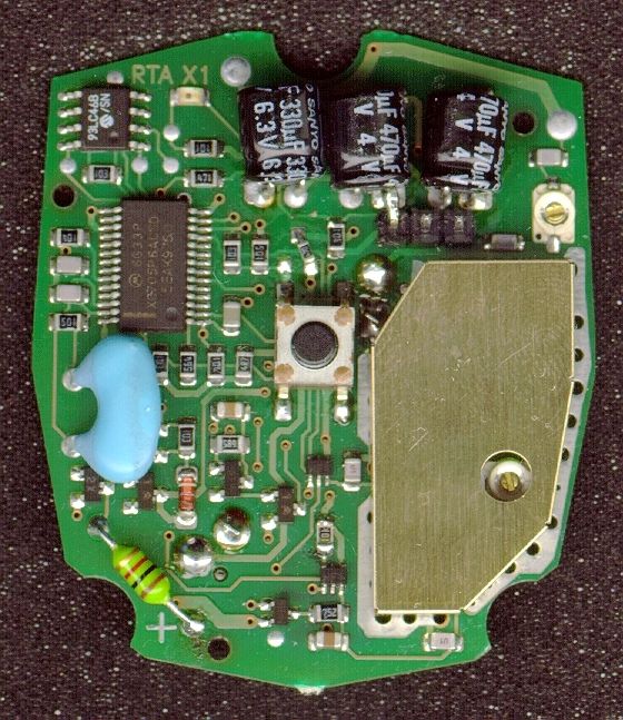
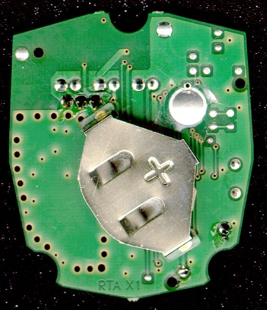
TEST REPORT October 4, 1999 1:18 pmINO 9907 1502 Page 21 of 42 CONFIDENTIAL AND PROPRIETARY Part 3.10 FA223, Inside Top View TEST REPORT October 4, 1999 1:18 pmINO 9907 1502 Page 22 of 42 CONFIDENTIAL AND PROPRIETARY Part 3.11 FA223, PWB Component Side TEST REPORT October 4, 1999 1:18 pmINO 9907 1502 Page 23 of 42 CONFIDENTIAL AND PROPRIETARY Part 3.12 FA223, PWB Foil Side and Battery Compartment TEST REPORT Page 24 of 42INO 9907 1502October 4, 1999 1:18 pm CONFIDENTIAL AND PROPRIETARY TEST REPORT October 4, 1999 1:18 pmINO 9907 1502 Page 25 of 42 CONFIDENTIAL AND PROPRIETARY Section 4Original Test Data / Plots Radiated Emissions TEST REPORT Page 26 of 42INO 9907 1502October 4, 1999 1:18 pm CONFIDENTIAL AND PROPRIETARY Part 4.1 Radiated Emissions Data, 30 MHz to 1000 MHz Criterion TechnologyWed Jul 21 18:40:05 1999 EUT: Model: FA223, Serial: #1 Manufacturer: Inovonics, inc. Tester: MEMSpecial ID: INO Q940 9907_1502 EUT Level: Pre-production EUT Information: Battery Powered EUT on Tabletop Test information: Three freq hop sequence (lo mid high), 10m, battery powered, FCC 15.247 Table 1: Scan List, sorted by margin to limit FCC-A, -30.0dB filter Freq, MHz ValueStsFCC-ATTHghtAzComment 919.033285.19m38.75280194Vfo high 911.322880.58m34.149164Vfo mid 906.356079.41m32.972172Vfo low 901.950039.13m-7.31267220Vband edge measurement 928.050028.16m-18.28263105Vband edge measurement Table 2: Scan List for FCC-A, sorted by Frequency, -30.0dB filter Freq, MHz ValueStsFCC-ATTHghtAzComment 901.950039.13m-7.31267220Vband edge measurement 906.356079.41m32.972172Vfo low 911.322880.58m34.149164Vfo mid 919.033285.19m38.75280194Vfo high 928.050028.16m-18.28263105Vband edge measurement Notes: The third column below contains alpha characters which pertain to the type of measurements made. The following are the definitions for those characters: q = Quasi Peak, m = Maxi- mized (cable, rotation and antenna height), s = scanned but no data taken, and a = average. For the first character in column four, a ‘-’ indicates that value is below the limit while an ‘*’ indicates that value is above the limit If the list is sorted using “I-sort”, then quasi-peak and average levels are weighted higher than peak levels and are moved to the front of the scan list. The following keys help to better understand the data: TT: Turntable position in degrees Hght: Height of antenna in centimeters Az: Azimuth, V = Vertical, H= Horizontal TEST REPORT October 4, 1999 1:18 pmINO 9907 1502 Page 27 of 42 CONFIDENTIAL AND PROPRIETARY Table 3: Complete Scan List Sorted by Frequency Freq, MHzI-valFinalStsTTHghtAzTimeComment 901.950032.8239.13m267220VWed Jul 21 18:01:44 1999band edge measurement 906.356073.0179.41m2172VWed Jul 21 18:10:26 1999fo low 911.322874.0580.58m9164VWed Jul 21 18:28:13 1999fo mid 919.033278.4085.19m280194VWed Jul 21 18:31:24 1999fo high 928.050020.9828.16m263105VWed Jul 21 18:33:41 1999band edge measurement TEST REPORT Page 28 of 42INO 9907 1502October 4, 1999 1:18 pm CONFIDENTIAL AND PROPRIETARY Part 4.2 Radiated Emissions Data, 1 GHz to 10 GHz level 1.5 compatible file Model: FA223, Serial: #1 Inovonics, inc. MEM INO Q940 Pre-production Battery Powered EUT on Tabletop, Orientation 1 Three freq hop sequence (lo mid high), 3m, battery powered, FCC 15.247 FrequencyIVal (pk)FVal (pk)Fval (avg)TurntableMast HtPolarizationComments (MHz)(dBuV/m)(dBuV/m)(dBuV/m)(deg)(m) 1812.7155.9051.9531.95631.01H2 x f o low 1822.6557.9554.0634.06621.03H2 x f o mid 1838.0760.4056.5936.59731.00H2 x f o high 2719.0732.0031.6111.61 3 x f o lownoise flr 2733.9836.4035.9415.94 3 x f o midnoise flr 2757.1134.8034.2614.26 3 x f o highnoise flr 3625.4231.5032.8312.83 4 x f o lownoise flr 3645.3033.4534.8714.87 4 x f o midnoise flr 3676.1436.5037.9017.901401.00V4 x f o high 4531.7852.9556.0536.052251.08V5 x f o low 4556.6352.5055.7635.762241.39V5 x f o mid 4595.1852.7556.4536.452211.07V5 x f o high 5438.1332.0539.3419.342191.01V6 x f o low 5467.9530.4537.9317.932211.00V6 x f o mid 5514.2130.5538.2118.212231.52V6 x f o high 6344.4947.6556.6136.612131.03V7 x f o low 6379.2850.6059.6239.622131.01V7 x f o mid 6433.2550.1059.3939.392151.12V7 x f o high 7250.8431.8543.4623.46 8 x f o lownoise flr 7290.6032.1043.8023.80 8 x f o midnoise flr 7352.2835.0547.6427.64 8 x f o highnoise flr 8157.2032.1043.9123.91 9 x f o lownoise flr 8201.9331.4042.8622.86 9 x f o midnoise flr 8271.3234.4546.7426.74 9 x f o highnoise flr 9063.5531.1046.6226.62 10 x f o lownoise flr 9113.2531.6547.0727.07 10 x f o midnoise flr 9190.3533.4049.2129.21 10 x f o highnoise flr TEST REPORT October 4, 1999 1:18 pmINO 9907 1502 Page 29 of 42 CONFIDENTIAL AND PROPRIETARY Inovonics, inc. MEM INO Q940 Pre-production Battery Powered EUT on Tabletop, Orientation 2 Three freq hop sequence (lo mid high), 3m, battery powered, FCC 15.247 FrequencyIVal (pk)FVal (pk)Fval (avg)TurntableMast HtPolarizationComments (MHz)(dBuV/m)(dBuV/m)(dBuV/m)(deg)(m) 1812.7161.8557.9037.90601.00V2 x f o low 1822.6558.5554.6634.66571.00V2 x f o mid 1838.0761.0057.1937.19591.00V2 x f o high 2719.0734.0033.6113.61 3 x f o lownoise flr 2733.9835.6535.1915.19 3 x f o midnoise flr 2757.1136.7536.2116.21 3 x f o highnoise flr 3625.4236.4537.7817.781061.10V4 x f o low 3645.3033.1534.5714.57 4 x f o midnoise flr 3676.1434.5035.9015.902221.00V4 x f o high 4531.7847.8550.9530.953461.45V5 x f o low 4556.6350.0053.2633.263421.44V5 x f o mid 4595.1851.7555.4535.453341.43V5 x f o high 5438.1327.0534.3414.34 6 x f o lownoise flr 5467.9526.8534.3314.333431.43V6 x f o mid 5514.2126.3534.0114.01 6 x f o highnoise flr 6344.4948.3057.2637.262451.29H7 x f o low 6379.2847.0056.0236.022391.20H7 x f o mid 6433.2549.2058.4938.492351.07H7 x f o high 7250.8432.5544.1624.16 8 x f o lownoise flr 7290.6032.4044.1024.10 8 x f o midnoise flr 7352.2832.3544.9424.94 8 x f o highnoise flr 8157.2031.7543.5623.56 9 x f o lownoise flr 8201.9332.8544.3124.31 9 x f o midnoise flr 8271.3232.7545.0425.04 9 x f o highnoise flr 9063.5531.5047.0227.02 10 x f o l…
Text truncated - open the document above for the full version.
Test Report
ADDENDUM: FIGURE B
Test Report
ADDENDUM: FIGURE C
Contact Information
Applicant
Jess Cobb(Manager of Program Mgmt)
Test Firm
Criterion Technology Corp.Lou Schornack
Technical Specifications
| # | Rule Parts | Frequency Range | Power Output | Emission |
|---|---|---|---|---|
| 1 | 15C | 906 MHz - 920 MHz | 5.00 mW | MID |
Other Applications from Inovonics Wireless Corporation

HCQ-IDTOUCH1
May 13, 2026Inovonics Wired Touchscreen Keypad
Equipment Class
DTS - Digital Transmission System
HCQBWA02
Aug 28, 2024Flush Mount Locator
Equipment Class
DSS - Part 15 Spread Spectrum Transmitter
HCQTBA
Sep 21, 2022TBA Module
Equipment Class
DSS - Part 15 Spread Spectrum Transmitter
HCQPFA01
Jul 14, 2022Fall Detect Transmitter
Equipment Class
DSS - Part 15 Spread Spectrum Transmitter
HCQ3B6BRGSA
Sep 22, 2020Bluetooth to EchoStream Bridge
Equipment Class
DTS - Digital Transmission System