HCQ3B6UXFH24MUniversal Transmitter
Inovonics Wireless Corporation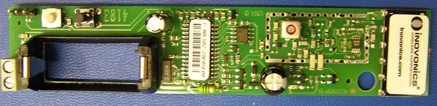
Click to zoom
Application Details
- Equipment Class
- DSS - Part 15 Spread Spectrum Transmitter
- Date of Grant
- Jun 03, 2004
- Application Purpose
- Original Equipment
- Date of Application
- Mar 16, 2004
- Equipment Note
- Universal Transmitter
- Frequency Range
- 907.00000000 - 919.00000000
- Country
- United States
Documents & Files
Document Text
Text extracted from the exhibit documents filed with the FCC. Open a document above to read the original.
Users Manual
User’s Manual FFC ID: HCQ3B6UXFH24M The FA-250M is a transmitter module, and operates together with a companion FA series receiver; thus, no user’s manual has been written for this device.
Cover Letter(s)
March 17, 2004 Federal Communications Commission Authorization and Standards Division 7435 Oakland Mills Road Columbia, MD 21046 Subject: Request for Confidentiality for FCC ID# HCQ3B6UXH24M Gentlemen: The following reports are marked confidential, and should be maintained in the non- public file. This confidentiality is necessary to protect proprietary information contained within these sections of the application for Certification. 1) Detailed Technical Description 2) Schematics 3) Block Diagram Thanks for your help. Sincerely, Donald J. Hume President
Cover Letter(s)
April 1, 2004 Ms. Linda Elliott Federal Communications Commission Authorization and Standards Division 7435 Oakland Mills Road Columbia, MD 21046 Re: FCC ID# HCQ3B6UXFH24M Correspondence Ref. No.: 26603 731 Confirmation Number: EA166940 Dear Ms. Elliott: The FCC ID on Form 731 was erroneously entered. The correct FCC ID should be HCQ3B6UXFH24M. Some documents are also re-submitted to reflect the correct FCC ID on the document’s footer. Thanks for your help. Sincerely, Amy Arguelles Executive Assistant to Donald Hume
Cover Letter(s)
March 17, 2004 Federal Communications Commission Authorization and Standards Division 7435 Oakland Mills Road Columbia, MD 21046 Subject: Request for Confidentiality for FCC ID# HCQ3B6UXFH24M Gentlemen: The following reports are marked confidential, and should be maintained in the non- public file. This confidentiality is necessary to protect proprietary information contained within these sections of the application for Certification. 1) Detailed Technical Description 2) Schematics 3) Block Diagram Thanks for your help. Sincerely, Donald J. Hume President
Cover Letter(s)
Applicant: Inovonics Wireless Corp. FCC ID: HCQ3B6UXFH24M Correspondence Ref. Number: 26726 731 Confirmation Number: EA166940 Re: “Please explain how this device complies with the modular transmitter requirements for a Part 15 device, as described in document DA 00-1407.” Compliance with Public Notice DA 00-1407 Public Notice DA 00-1407 contains guidelines and requirements for obtaining modular transmitter approval. The transmitter in question is a self-contained device having its own reference oscillator, permanently attached antenna, and RF shielding. The only external connection to the module is the switch contact input. 1. This module contains shielding to mitigate RFI and does not rely upon external shielding from the device to which it is attached. 2. The switch contact input is buffered by the micro-controller within the module. 3. This module is designed to operate from a 3V primary cell within the module. An internal voltage regulator provides a stable power supply to the VCO and PA driver stages. 4. The antenna is permanently affixed to the module, per 15.204. The Internal Photo inserted from the initial report has been updated to designate the antenna structure. 5. The module was tested as a stand-alone device. 6. The module is labeled with the FCC ID. In addition, the products in which it is integrated are labeled with the FCC ID. 7. The module complies with Part 15.247 of the FCC rules. No combination of input stimuli exist that could cause the module to operate in a manner that is not consistent with the rules. 8. The module complies with MPE requirements, as outlined in the MPE exhibit.
External Photos
External Photos FFC ID: HCQ3B6UXFH24M The FA-250M is a transmitter module. There are no external photos.
ID Label/Location Info
CONFIDENTIAL DOCUMENT Confidential to InovonicsFA-250M FCC LabelRev A FA-250M (Module) FCC Label 04229A CONFIDENTIAL DOCUMENTATION The information contained in this document is confidential to and the sole property of Inovonics Corporation. Receipt of this information requires the existence and full acceptance of the terms and conditions of a Non Disclosure Agreement signed by the Inovonics Corporation and the Recipient. This documentation is not to be reproduced or redistributed except as provided in the Non Disclosure Agreement. Rev. LevelDescriptionDate AInitial release MATERIAL: .002” THICK 3M 7381 VOIDABLE (TAMPER EVIDENT) WHITE MYLAR WITH .001” MATTE LAMINATION (FOR PROTECTION FROM INK SMEARING) AND PERMANENT ADHESIVE APPLIED TO THE BACKSIDE ARTWORK: NONE TEXT: BLACK WITH ARIAL FONT HAVING HIGHLIGHTING, SPACING, AND SIZES APPROXIMATELY AS SHOWN LABEL SIZE: ------” X ------” (SHOWN TO 3 TIMES SCALE) WITH .125 RADIUS ON EACH CORNER (NOT SHOWN) AND NO BORDER PACKAGING AND LABEL ORIENTATION: LABELS TO BE SUPPLIED ON TOP SIDE OF ROLL STOCK WITH TEXT READABLE AS VIEWED FROM BOTTOM (SHORT) EDGE OF ROLL www.inovonicswireless.com FA-250M FCC ID: HCQ3B6UXFH24M IC: 2309UXFH24M
Internal Photos
FCC ID: HCQ3B5UXFH24M FA-250M 3/17/2004 Page 1 of 1 FA-250M Transmitter Photographs Photograph of the FA-250M board with the shield removed. Battery Holder (CR-123 or equivalent) RF Shield Antenna Photograph of an FA-250M board with the shield in place. Note PC mounted antenna is at the far right end of the board. Photograph of the reverse side of the FA-250M board.
Internal Photos
FCC ID: HCQ3B6UXFH24M FA-250M 4/1/2004 Page 1 of 1 FA-250M Transmitter Photographs Photograph of the FA-250M board with the shield removed. Battery Holder (CR-123 or equivalent) RF Shield Antenna Photograph of an FA-250M board with the shield in place. Note PC mounted antenna is at the far right end of the board. Photograph of the reverse side of the FA-250M board.
Parts List/Tune Up Info
Parts List/Tune up Info FFC ID: HCQ3B6UXFH24M This exhibit does not apply to this device.
RF Exposure Info
CONFIDENTIAL FCC ID: HCQ3B5UXFH24M FA-250M 3/17/2004 FA-250M Transmitter Certification Testing – Additional Notes Duty Cycle: The duty cycle is calculated over a 100 mSec averaging window as specified in the rules. The message packet contains a total of 213 pulses each 20 uSec in duration, for a total transmitter on time of 4.26 mSec with represents a worst- case duty cycle of 4.26%. The duty cycle correction used is the maximum of 10%. MPE: Calculation for compliance with MPE requirements (Section 2.1091) using a worst case of 0.25 Watt, unity antenna gain, and the f/300 (mW/cm 2 ) limit for general applications. This device is used in fixed locations and is not carried or worn by the end user. The key factor is duty cycle. Under normal conditions, a 12-packet message is sent a maximum of once every 15 minutes. Worst case, a 12-packet message is sent, once per minute, or 72 packets in a 6-minute period. Total On time per packet = 4.26 mSec (for maximum packet length) Duty Cycle = (4.26 x 72) mSec/(6x60x1000) mSec = 0.0852% EIRP = (0.25W)(0.000852) = 213 microwatt. Using a distance of 20 cm: 213 microwatt / (4 pi 20 2 ) = 42.38 nW/cm 2 Dwell Time: The Dwell Time is the length of one packet. The worst-case dwell time for an extended length packet is 40.1 mSec. The standard packet is about 30 mSec duration. A worst-case transmission rate, corresponding to a repeated change of state transmissions would result in a maximum of 12 packets in any 10-second period with each packet on a different frequency. The maximum dwell time is thus the dwell time of an extended packet or 40.1 ms. Modular Approval: Public Notice DA 00-1407 contains guidelines and requirements for obtaining modular transmitter approval: A. The FA-250M transmitter module is a self-contained device, powered by an internal single cell, 2/3 A size LiMnO2 primary cell (nominally 3 Volts). An internal voltage regulator provides a stable power supply to the VCO and PA driver stages. B. The module has its own reference oscillator, permanently attached internal antenna per 15.204, and RF shielding over the transmitter portion of the module. C. An external switch or data input activates the module, to signal a change of state. This input is buffered by the internal microcontroller. D. The module complies with all applicable FCC rules including 15.247. E. The module was tested as a stand-alone device. CONFIDENTIAL FCC ID: HCQ3B5UXFH24M FA-250M 3/17/2004 Measurements performed at Inovonics Wireless Corp. lab Equipment used: HP-8594E Spectrum Analyzer Conducted Power Output: The antenna was removed and a coax was temporarily connected to allow for direct measurement of power using the spectrum analyzer. The power output was measured at +21 dBm was measured into 50 ohms. Spectrum Plots: The following two spectrum plots were made using a test antenna closely coupled to the test unit. Spectrum Plot 1 shows two adjacent channels with modulation. Compliance with section 15.247(a)(1) is demonstrated with a test sample configured with firmware allowing two adjacent channels to be captured. Plot 1 also shows the 20 dB bandwidth of a single channel of 300 kHz, to demonstrate compliance with 15.247(a)(1)(i). CONFIDENTIAL FCC ID: HCQ3B5UXFH24M FA-250M 3/17/2004 Plot 2 demonstrates compliance with 15.247(a)(1)(i) — Number of hopping channels. This is a stored display of many sequential transmissions to show the overall band occupied by the transmitter.
Test Report
CONFIDENTIAL FCC ID: HCQ3B6UXFH24M FA-250M 4/1/2004 FA-250M Transmitter Certification Testing – Additional Notes Duty Cycle: The duty cycle is calculated over a 100 mSec averaging window as specified in the rules. The message packet contains a total of 213 pulses each 20 uSec in duration, for a total transmitter on time of 4.26 mSec with represents a worst- case duty cycle of 4.26%. The duty cycle correction used is the maximum of 10%. MPE: Calculation for compliance with MPE requirements (Section 2.1091) using a worst case of 0.25 Watt, unity antenna gain, and the f/300 (mW/cm 2 ) limit for general applications. This device is used in fixed locations and is not carried or worn by the end user. The key factor is duty cycle. Under normal conditions, a 12-packet message is sent a maximum of once every 15 minutes. Worst case, a 12-packet message is sent, once per minute, or 72 packets in a 6-minute period. Total On time per packet = 4.26 mSec (for maximum packet length) Duty Cycle = (4.26 x 72) mSec/(6x60x1000) mSec = 0.0852% EIRP = (0.25W)(0.000852) = 213 microwatt. Using a distance of 20 cm: 213 microwatt / (4 pi 20 2 ) = 42.38 nW/cm 2 Dwell Time: The Dwell Time is the length of one packet. The worst-case dwell time for an extended length packet is 40.1 mSec. The standard packet is about 30 mSec duration. A worst-case transmission rate, corresponding to a repeated change of state transmissions would result in a maximum of 12 packets in any 10-second period with each packet on a different frequency. The maximum dwell time is thus the dwell time of an extended packet or 40.1 ms. Modular Approval: Public Notice DA 00-1407 contains guidelines and requirements for obtaining modular transmitter approval: A. The FA-250M transmitter module is a self-contained device, powered by an internal single cell, 2/3 A size LiMnO2 primary cell (nominally 3 Volts). An internal voltage regulator provides a stable power supply to the VCO and PA driver stages. B. The module has its own reference oscillator, permanently attached internal antenna per 15.204, and RF shielding over the transmitter portion of the module. C. An external switch or data input activates the module, to signal a change of state. This input is buffered by the internal microcontroller. D. The module complies with all applicable FCC rules including 15.247. E. The module was tested as a stand-alone device. CONFIDENTIAL FCC ID: HCQ3B6UXFH24M FA-250M 4/1/2004 Measurements performed at Inovonics Wireless Corp. lab Equipment used: HP-8594E Spectrum Analyzer Conducted Power Output: The antenna was removed and a coax was temporarily connected to allow for direct measurement of power using the spectrum analyzer. The power output was measured at +21 dBm was measured into 50 ohms. Spectrum Plots: The following two spectrum plots were made using a test antenna closely coupled to the test unit. Spectrum Plot 1 shows two adjacent channels with modulation. Compliance with section 15.247(a)(1) is demonstrated with a test sample configured with firmware allowing two adjacent channels to be captured. Plot 1 also shows the 20 dB bandwidth of a single channel of 300 kHz, to demonstrate compliance with 15.247(a)(1)(i). CONFIDENTIAL FCC ID: HCQ3B6UXFH24M FA-250M 4/1/2004 Plot 2 demonstrates compliance with 15.247(a)(1)(i) — Number of hopping channels. This is a stored display of many sequential transmissions to show the overall band occupied by the transmitter.
Test Setup Photos
Test Setup Photos FFC ID: HCQ3B6UXFH24M These are included in the Test Report.
Contact Information
Applicant
Jess Cobb(Manager of Program Mgmt)
Technical Contact
Inovonics Wireless CorporationDonald Hume
[email protected]303-939-9336
315 CTC Blvd. · Louisville, Colorado · United States
Non-Technical Contact
Inovonics Wireless Corp.Amy Arguelles
[email protected]303-209-7167
Test Firm
Criterion Technology Corp.Lou Schornack
Technical Specifications
| # | Rule Parts | Frequency Range | Power Output |
|---|---|---|---|
| 1 | 15C | 907 MHz - 919 MHz | 125.00 mW |
Other Applications from Inovonics Wireless Corporation

HCQ-IDTOUCH1
May 13, 2026Inovonics Wired Touchscreen Keypad
Equipment Class
DTS - Digital Transmission System
HCQBWA02
Aug 28, 2024Flush Mount Locator
Equipment Class
DSS - Part 15 Spread Spectrum Transmitter
HCQTBA
Sep 21, 2022TBA Module
Equipment Class
DSS - Part 15 Spread Spectrum Transmitter
HCQPFA01
Jul 14, 2022Fall Detect Transmitter
Equipment Class
DSS - Part 15 Spread Spectrum Transmitter
HCQ3B6BRGSA
Sep 22, 2020Bluetooth to EchoStream Bridge
Equipment Class
DTS - Digital Transmission System