HDC-73108GWLoRa 8-Channel PoE Gateway
Adtran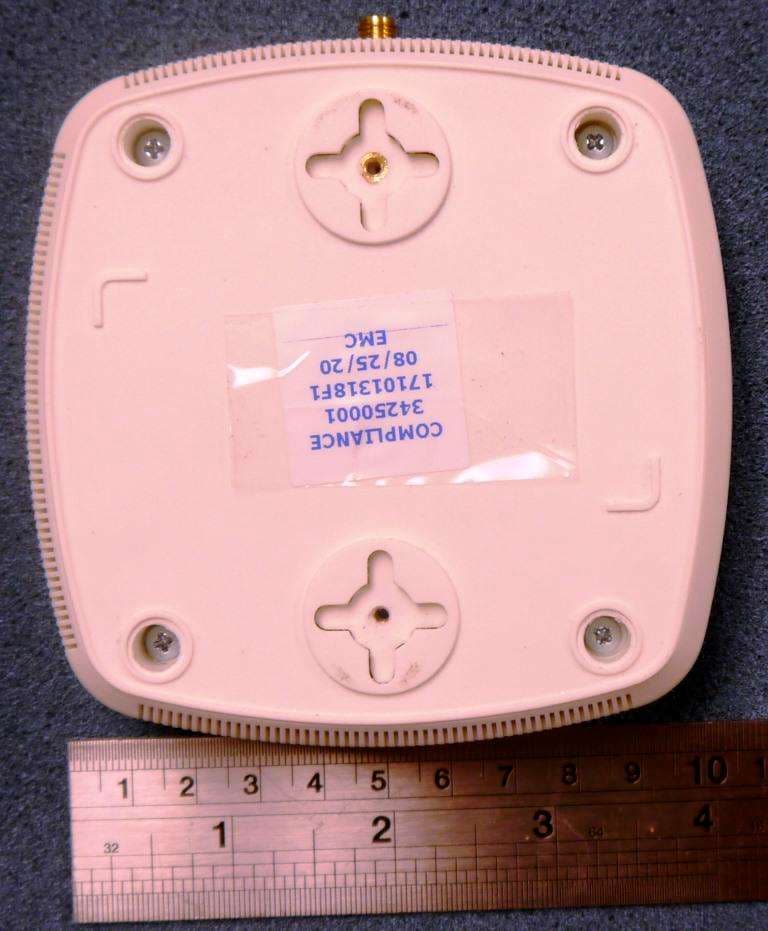
Click to zoom
Application Details
- Equipment Class
- DTS - Digital Transmission System
- Date of Grant
- Oct 28, 2020
- Application Purpose
- Original Equipment
- Date of Application
- Oct 25, 2020
- Equipment Note
- LoRa 8-Channel PoE Gateway
- Frequency Range
- 923.30000000 - 927.50000000
- Company
- Adtran
- Country
- United States
Documents & Files
Document Text
Text extracted from the exhibit documents filed with the FCC. Open a document above to read the original.
Users Manual
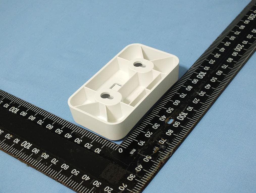
Quick Start f WARNING! Read all warnings, cautions, notes and installation instructions before installing or servicing this equipment. f AVERTISSMENT! Lisez tous les avertissements et mises en garde avant l’installation de cet équipement ou la réalisation de toute opération de maintenance. Overview This quick start describes how to install, configure, and troubleshoot ADTRAN’s 8-channel Enterprise LoRaWAN gateway, a LoRa Certified gateway that provides Internet of Things (IoT) connectivity using the LoRaWAN technology publicly provided over the 902 to 928 MHz frequencies. This robust gateway can be manged using the ADTRAN LoRaWAN Management App over Bluetooth to provide instantaneous connection between the LoRaWAN gateway, the LoRaWAN Network Server (LNS), and any nearby LoRa devices. ■“Installing the LoRaWAN Gateway” on page 2 ■“Supplying Power to the LoRaWAN Gateway” on page 3 ■“Connecting to the LoRaWAN Gateway” on page 3 ■“Understanding the Status LEDs” on page 4 Figure 1. LoRaWAN Gateway LEDs Aux PWR PoE/Net Antenna Mount f WARNING! f CAUTION! g NOTE WARNING indicates a hazard which, if not avoided, could result in death, injury or serious property damage. CAUTION indicates a hazard which, if not avoided, could result in service interruption, damage to the equipment, or minor property damage. NOTES inform the user of additional, but important, information or features. ADTRAN 7310-8 LoRaWAN Gateway 8-channel Enterprise LoRaWAN Gateway September 2020 617101318F1-13A P/N: 17101318F1 2617101318F1-13A Installing the LoRaWAN Gateway g NOTE Refer to the national, state and local electrical codes for the requirements for power, grounding, wiring, and installation methods. Package Contents ■ ADTRAN’s 8-channel Enterprise LoRaWAN gateway ■ One external antenna ■ RJ-45 Ethernet cable ■ Mounting kit containing: ♦ Wall/Ceiling mount hardware: mounting plate, two anchors and associated screws ♦ Two T-rail mounting brackets (9/16 and 15/16) for recessed drop ceilings ■ Quick Start f CAUTION! The ADTRAN Enterprise LoRaWAN gateway is intended for indoor use only. Ethernet, PoE cables, and attached equipment are intended for use within the same building with equipotential bonding, and not intended to be placed in separate buildings or structures. Failure to deploy as described could result in permanent damage from lightning or other electrical events and voids the warranty. Prior to Installation Before installing the equipment, inspect the gateway. If damage has occurred during shipping, file a claim with the carrier, and then contact ADTRAN Customer Support. For more information, refer to the product warranty available online at https://adtran/wp_support_warranty. Installing the Antenna To install the provided antenna onto the LoRaWAN gateway, attach the external antenna onto the antenna port on the left side of the gateway (as shown in Figure 1 on page 1. Mounting the LoRaWAN Gateway to a Ceiling or Wall The LoRaWAN gateway should be positioned for maximum throughput and range between other gateways and wireless client devices. Follow these instructions to mount the LoRaWAN gateway to an interior ceiling or wall using the enclosed ceiling/wall mounting kit: 1. Install the antenna onto the appropriate antenna port on the LoRaWAN gateway. 2. Drive the short screws into the metal screw receptacles on the bottom of the LoRaWAN gateway until they are inserted into the keyed slots on the mounting bracket. If extra space is required, use the spacers and long screws provided with the T-rail mounting hardware kit to increase the space between the unit and the mounting bracket. Leave enough of the long screws exposed above the spacer to ensure they can be inserted into the keyed slots on the mounting bracket. 3. Using the plastic mounting bracket as a template, mark the location to insert the screw anchors. 4. Press the point of the screw anchors into the sheetrock at the marks and drive them into the wall using a Phillips-head screwdriver. g NOTE When installing the LoRaWAN gateway into the wall, be sure that the wall anchors are oriented vertically so that the cables will be pointing downward in the final installation. 5. Insert the long screws through the recessed holes in the plastic mounting bracket and drive them into the metal anchors. 6. Mount the LoRaWAN gateway on the mounting bracket by inserting the screws on the back of the gateway into the keyed slots on the mounting bracket and rotating the unit clockwise 90 degrees to secure it on the bracket. Figure 2. LoRaWAN Gateway Ceiling or Wall Mount Keyed Slots Mounting Bracket Long Screws Short Screws Mounting Screw Receptacles 617101318F1-13A3 Mounting the LoRaWAN Gateway to a Dropped Ceiling The LoRaWAN gateway ships with a T-rail mounting kit to mount the gateway on the ceiling tile separators of standard dropped ceilings. The mounting clips come in two sizes and can be mounted to either recessed (using the spacer) or flush dropped ceiling T-rails. LoRaWAN gateways should be positioned for maximum throughput and range between other gateways and wireless client devices. To mount the gateway to a dropped ceiling: 1. Install the antenna onto the appropriate antenna port on the LoRaWAN gateway. 2. Attach the appropriate size ceiling clips to the bottom cover of the LoRaWAN gateway using the provided short screws as shown in Figure 3: Figure 3. Attach the Ceiling Clips to the LoRaWAN Gateway g NOTE If extra space is required to accommodate recessed dropped ceiling tiles, use the provided spacers and longer screws included in the T-rail ceiling mount kit. 3. Once the ceiling clips are attached to the LoRaWAN gateway, line up the T-rail clips with an appropriately sized rail and press the unit onto the rail until it snaps into place. Supplying Power to the LoRaWAN Gateway The LoRaWAN gateway does not have a power switch. It is powered on when connected to a network device that supplies PoE based on the IEEE 802.3at standard. To power the LoRaWAN gateway,…
Text truncated - open the document above for the full version.
Cover Letter(s)
SGS North America Inc. Consumer and Retail 620 Old Peachtree Road Suite 100 Suwanee GA 30024 t (770) 570-1800 f (770) 277-1240 www.sgs.com Member of the SGS Group (SGS SA) Attn: Director of Certification Confidentiality Request regarding application for FCC ID: HDC-73108GW LONG TERM CONFIDENTIALITY Pursuant to 47 CFR Section 0.459 and 0.457 of the commission’s rules, the applicant hereby requests confidential treatment of the documents listed below, associated with the certification application referenced above. Schematics Block diagrams Technical Description The documents above contain proprietary information not released to the public. Public disclosure of this information may prove harmful to the business of the applicant. Sincerely, Jeremy Pickens Agent for ADTRAN, Inc. SGS North America Title: RF Lab Manager Date: 18 September 2020
Cover Letter(s)
SGS North America Inc. Consumer and Retail 620 Old Peachtree Road Suite 100 Suwanee GA 30024 t (770) 570-1800 f (770) 277-1240 www.sgs.com Member of the SGS Group (SGS SA) Attn: Director of Certification Cover letter regarding application for FCC ID: HDC-73108GW The applicant is seeking equipment authorization for the LoRaWAN Gateway, Model 7310-8. This equipment contains a LoRa radio operating in the frequency range 923.3MHz – 927.5MHz. Additionally, a certified 2.4GHz module (FCC ID: 2AKZA-QCA9377) will be collocated with the LoRa radio in the host device. While the certified module supports 2.4GHz WLAN and Bluetooth LE, only the Bluetooth LE operation is active within this device. Spurious emissions and intermodulation products have been evaluated and found to be compliant. Additionally, RF exposure conditions for simultaneous transmissions have also been addressed. This device is for professional installation only, and an attestation has been included with the filing documentation. Sincerely, Jeremy Pickens Agent for Adtran SGS North America Title: RF Lab Manager Date: 30 September 2020
Cover Letter(s)
General Business General Business Date: August 23, 2020 TO: Federal Communication Commission Equipment Authorization Branch 7435 Oakland Mills Road Columbia, MID 21046 Regarding: HDC-73108GW To whom it may concern: We, the undersigned, hereby authorize Jeremy Pickens to act on our behalf in all manners relating to application for equipment authorization with respect to the FCC ID above, including signing of all documents relating to these matters. Any and all acts carried out by the agent on our behalf shall have the same effect as acts of our own. We, the undersigned, hereby certify that we are not subject to a denial of federal benefits, that includes FCC benefits, pursuant to Section 5301 of the Anti-Drug Abuse Act of 1988, 21 U.S.C. 853(a). Where our agent signs the application for certification on our behalf, I acknowledge that all responsibility for complying with the terms and conditions for Certification, as specified by SGS North America, Inc., still resides with ADTRAN, Inc. This authorization is valid until further written notice from the applicant. Name (Printed): Doug Parker Title: Regulatory Compliance Engineering Manager Signature: On behalf of Company: ADTRAN Telephone: (256)-963-6937
Cover Letter(s)
Applicant Declaration Applicant Declaration Rev:0.0 SGS North America Inc. 620 Old Peachtree Road SUITE 100 Suwanee, Georgia 30024 United States Applicant Legal Business Name ADTRAN, Inc Address 901 Explorer Blvd, Huntsville, Alabama 35806 Grantee Code 0005813993 FCC ID HDC-73108GW Authorized Contact Name Doug Parker Contact Email [email protected] Contact Phone (256) 963-6937 I, the undersigned, certify that I am an authorized signatory for the Applicant and therefore declare; a) in accordance with 47CFR2.911(d), all of the statements herein and the exhibits attached hereto are true and correct to the best of my knowledge and belief. b) in accepting a Grant of Equipment Authorization issued by a TCB, under the authority of the FCC, as a result of the representations made in this application, the Applicant is responsible for: (1) labeling the equipment with the exact FCC ID as specified in this application, (2) compliance statement labeling pursuant to the applicable rules, (3) compliance of the equipment with the applicable technical rules, c) if the Applicant is not the actual manufacturer of the equipment, appropriate arrangements have been made with the manufacturer to ensure that production units of this equipment will continue to comply with the FCC’s technical requirements. d) in accordance with 47 CFR 2.909 and KDB394321, the Applicant has read, understood and agrees to accept that they are the responsible party and agree to abide by their responsibilities as specified under 47 CFR 2.909 and KDB394321. e) in accordance with ISO17065, FCC KDB641163, FCC KDB610077, KDB394321 and RSP-100, the Applicant has read, understood, accepts and agrees to abide by the post market surveillance requirements. (1) the Applicant understands, accepts and agrees that a sample may be requested for surveillance testing. (2) the Applicant shall make provisions to always have a production sample available upon request by SGS, FCC and/or ISED. (3) the Applicant shall, upon request by SGS, at the Applicant’s expense, provide a production sample of the requested product to SGS, FCC and/or ISED as instructed. The sample shall include all support devices, cables, software, accessories or other hardware or software required for evaluation, review, certification and audit surveillance of products certified by SGS. f) neither the Applicant nor any party to the application is subject to a denial of Federal benefits, that includes FCC benefits, pursuant to Section 5301 of the Anti-Drug Abuse Act of 1988, 21 U.S.C. §862 because of a conviction for possession or distribution of a controlled substance. See 47CFR 1.2002(b) for the definition of a “party” for these purposes. g) the Applicant has read, understood, accepts and agrees to abide by the SGS North America, Inc.(TCB) terms and conditions. Link to CFRs: https://www.fcc.gov/wireless/bureau-divisions/technologies-systems-and-innovation-division/rules-regulations-title-47 Link to KDBs: https://apps.fcc.gov/oetcf/kdb/index.cfm Link to RSP-100: https://www.ic.gc.ca/eic/site/smt-gst.nsf/eng/sf01130.html Applicant Signature: Date: August 23, 2020 Print Name: Doug Parker Title: Regulatory Compliance Engineering Manager *NOTE: This declaration cannot be signed by an Agent, it shall be signed by an authorized person listed in the FCC database
Cover Letter(s)
Professional Installation Attestation Date: September 10, 2020 TO: Federal Communication Commission Equipment Authorization Branch 7435 Oakland Mills Road Columbia, MID 21046 Regarding: FCC ID: HDC-73108GW IC: 2250A-73108GW To whom it may concern: Please be advised that due to the unique market and function targeted by this product, this product will need a specially trained professional in configuring and installing the product. We hereby declare that the product will be distributed through controlled distribution channel which have specially trained professionals to install this product and it will not be sold directly to the general public through retail stores. Thank you for your attention, Doug Parker Regulatory Compliance Engineering Manager ADTRAN, Inc. 901 Explorer Blvd Huntsville, Alabama 35806 (256)-963-6937 [email protected]
External Photos
EXTERNAL PHOTOS FCC ID: HDC-73108GW IC: 2250A-73108GW 2 © SGS SA 2016 ALL RIGHTS RESERVED TOP 3 © SGS SA 2016 ALL RIGHTS RESERVED BOTTOM 4 © SGS SA 2016 ALL RIGHTS RESERVED LEFT SIDE 5 © SGS SA 2016 ALL RIGHTS RESERVED RIGHT SIDE 6 © SGS SA 2016 ALL RIGHTS RESERVED ANTENNA PORT WWW.SGS.COM
ID Label/Location Info
1.00” SEE QUICK START GUIDE FOR INPUT POWER CONNECTIONS. SERIAL NO. SERIAL NO. This device complies with part 15 of FCC rules. Operation is subject to the following two conditions: (1) This device may not cause harmful interference, and (2) This device must accept any interference received, including interference that may cause undesired operation. CAN ICES-3 (A)/NMB-3(A) 901 EXPLORER BLVD. HUNTSVILLE, AL 35806 USA WWW.ADTRAN.COM 7310-8 LoRaWAN Gateway WT: 0.25 LBS. INPUT: 48Vdc , 0.1A (POE) or 5Vdc , 1.0A (USB) P/N: 17101318F1 FCC ID: HDC-73108GW IC: 2250A-73108GW FCC ID: 2AKZA-QCA9377 IC: 22364-QCA9377 Contains Contains PRODUCT DRAWN BYENGINEERMECH ENG. TITLE SCALEDWG. NO. 1:1 901 EXPLORER BLVD. P.O. BOX 140000 HUNTSVILLE, AL 35814-4000 L. SESSIONSD. ETZKORNJ. CHALMERS 3299912-E 7310-8 LoRaWAN GATEWAY PRODUCT LABEL DATEREVECO# COMMENT 06/10/20 @A N/A ORIGINAL REV 10/12/20 @B N/A ADDED “Contains” TO LABEL NOTES: 1. PRINT PER ARTWORK SUPPLIED. 2. MATERIAL: .002 WHITE MYLAR SUBSTRATE; BLACK LETTERING, .001 CLEAR MYLAR OVERLAY LAMINATED, FLEXCON L-344 OR UL APPROVED EQUAL PRESSURE SENSITIVE ADHESIVE BACKSIDE. 3. FONT: HELVETICA NEUE. NO FONT SUBSTITUTIONS PERMITTED. 4. FILM: EMULSION SIDE UP. 5. FOR COMPLIANCE USE ONLY: CELTUS, ESD, FCCR, ICR, ICCA, FCCA AND ADTAD 6. FINISHED PRODUCT MUST BE RoHS COMPLIANT. 3.00" 1.25" PANETONE COOL GREY 8 C R 0.03"
ID Label/Location Info
SEE QUICK START GUIDE FOR INPUT POWER CONNECTIONS. SERIAL NO. SERIAL NO. This device complies with part 15 of FCC rules. Operation is subject to the following two conditions: (1) This device may not cause harmful interference, and (2) This device must accept any interference received, including interference that may cause undesired operation. CAN ICES-3 (A)/NMB-3(A) 901 EXPLORER BLVD. HUNTSVILLE, AL 35806 USA WWW.ADTRAN.COM 7310-8 LoRaWAN Gateway WT: 0.25 LBS. INPUT: 48Vdc , 0.1A (POE) or 5Vdc , 1.0A (USB) FCC ID: HDC-73108GW IC: 2250A-73108GW FCC ID: 2AKZA-QCA9377 IC: 22364-QCA9377 P/N: 17101318F1
Internal Photos
INTERNAL PHOTOS FCC ID: HDC-73108GW IC: 2250A-73108GW 2 © SGS SA 2016 ALL RIGHTS RESERVED 3 © SGS SA 2016 ALL RIGHTS RESERVED 4 © SGS SA 2016 ALL RIGHTS RESERVED WLAN Module 5 © SGS SA 2016 ALL RIGHTS RESERVED 6 © SGS SA 2016 ALL RIGHTS RESERVED 7 © SGS SA 2016 ALL RIGHTS RESERVED 8 © SGS SA 2016 ALL RIGHTS RESERVED BLE MODULE BOARD 9 © SGS SA 2016 ALL RIGHTS RESERVED BLE MODULE BOARD 10 © SGS SA 2016 ALL RIGHTS RESERVED LORA MODULE 11 © SGS SA 2016 ALL RIGHTS RESERVED LORA MODULE 12 © SGS SA 2016 ALL RIGHTS RESERVED LORA MODULE 13 © SGS SA 2016 ALL RIGHTS RESERVED LORA MODULE WWW.SGS.COM
RF Exposure Info
Test Report Number: 4670216EMC02 Rev:0 ADTRAN, Inc. / 7310-8 Page: 1 of 5 Remarks: This report details the results of the testing carried out on one sample, the results contained in this test report do not relate to other samples of the same product. The manufacturer should ensure that all products in series production are in conformity with the product sample detailed in this report. This document is issued by the Company under its General Conditions of Service accessible at http://www.sgs.com/en/Terms-and- Conditions.aspx. Attention is drawn to the limitation of liability, indemnification and jurisdiction issues defined therein. Any holder of this document is advised that information contained hereon reflects the Company’s findings at the time of its intervention only and within the limits of Client’s instructions, if any. The Company’s sole responsibility is to its Client and this document does not exonerate parties to a transaction from exercising all their rights and obligations under the transaction documents. Any unauthorized alteration, forgery or falsification of the content or appearance of this document is unlawful, and offenders may be prosecuted to the fullest extent of the law. RF Exposure Report Project Number: 4670216 Proposal Number: 11235 Report Number: 4670216EMC02 Revision Level: 1 Client: ADTRAN, Inc. Equipment Under Test: LoRaWAN Gateway Model / HVIN: 7310-8 Part Number: 17101318F FCC ID: HDC-73108GW Applicable Standards: 47 CFR §§ 2.1091 FCC KDB 447498 D01 General RF Exposure Guidance v06 Report issued on: 12 October 2020 Result: Compliant Prepared by: Jeremy Pickens, RF Lab Manager Reviewed by: David Schramm, Operations Manager Test Report Number: 4670216EMC02 Rev:0 ADTRAN, Inc. / 7310-8 Page: 2 of 5 SGS North America Inc. Consumer and Retail 620 Old Peachtree Road NW, Suite 100, Suwanee, GA 30024 t (770) 570-1800 www.sgs.com Member of the SGS Group (SGS SA) TABLE OF CONTENTS 1 GENERAL INFORMATION ............................................................................................................................................. 3 1.1 CLIENT INFORMATION ................................................................................................................................................... 3 1.2 TEST LABORATORY ....................................................................................................................................................... 3 1.3 GENERAL INFORMATION OF EUT – LORA RADIO ......................................................................................................... 3 1.4 GENERAL INFORMATION OF EUT – BLUETOOTH RADIO ............................................................................................... 3 2 RF EXPOSURE ................................................................................................................................................................... 4 2.1 TEST RESULT ................................................................................................................................................................. 4 2.2 TEST METHOD ............................................................................................................................................................... 4 2.3 SINGLE TRANSMISSION RF EXPOSURE LEVELS (MW/CM 2 ) ............................................................................................ 4 2.4 SIMULTANEOUS TRANSMISSIONS ................................................................................................................................... 4 4 REVISION HISTORY ........................................................................................................................................................ 5 Test Report Number: 4670216EMC02 Rev:0 ADTRAN, Inc. / 7310-8 Page: 3 of 5 SGS North America Inc. Consumer and Retail 620 Old Peachtree Road NW, Suite 100, Suwanee, GA 30024 t (770) 570-1800 www.sgs.com Member of the SGS Group (SGS SA) 1 General Information 1.1 Client Information Name: ADTRAN, Inc. Address: 901 Explorer Blvd. City, State, Zip, Country: Huntsville, AL 35806 1.2 Test Laboratory Name: SGS North America, Inc. Address: 620 Old Peachtree Road NW, Suite 100 City, State, Zip, Country: Suwanee, GA 30024, USA Accrediting Body: A2LA Type of lab: Testing Laboratory Certificate Number: 3212.01 1.3 General Information of EUT – LoRa Radio EUT: LoRaWAN Gateway Model Number / HVIN: 7310-8 Part Number: 17101318F Serial Number: J3H213 Frequency Range: 923.3 – 927.5 MHz Number of channels: 8 Modulation type: LoRa Channel spacing: 600 kHz Antenna: External Dipole: 2.0dBi (Taoglas, M/N: TI.19.2113) External Dipole: 3.0dBi (Siretta, M/N: Delta 22B) Rated Voltage: 54Vdc PoE Sample Received Date: 03 SEP 2020 Dates of testing: 08 SEP – xx SEP 2020 1.4 General Information of EUT – Bluetooth Radio FCC ID: 2AKZA-QCA9377 IC: 22364-QCA9377 Frequency Range: 2402 – 2480 MHz 1 Number of channels: 40 Modulation type: GFSK (1Mbps BLE) Channel spacing: 2 MHz Antenna: Dipole (Inaccessible): 1.6dBi (Molex, M/N: TI.19.2113) Rated Voltage: 5Vdc Powered from host Note: Although the certified module supports WLAN operation, only the BLE functions will be enabled. Test Report Number: 4670216EMC02 Rev:0 ADTRAN, Inc. / 7310-8 Page: 4 of 5 SGS North America Inc. Consumer and Retail 620 Old Peachtree Road NW, Suite 100, Suwanee, GA 30024 t (770) 570-1800 www.sgs.com Member of the SGS Group (SGS SA) 2 RF Exposure 2.1 Test Result Test Description Product Specific Standard Test Result RF Exposure FCC Part 1.1310 Compliant 2.2 Test Method Using the maximum measured conducted power, the power density was calculated. Maximum antenna gain was assumed for this exercise. For BLE, the power from the FCC grant was used. 2.3 Single transmission RF Exposure Levels (mW/cm 2 ) 2.4 Simultaneous transmissions Simultaneous Transmissions - Percent of Limit Sub GHz Bluetooth LE Sub GHz 22.5% Bluetooth 22.5% Conducted Power w/tolerance Antenn…
Text truncated - open the document above for the full version.
Test Report
Test Report Number: 4670216EMC01 Rev: 0 ADTRAN, Inc. / 7310-8 Page: 1 of 40 Remarks: This report details the results of the testing carried out on one sample; the results contained in this test report do not relate to other samples of the same product. The manufacturer should ensure that all products in series production are in conformity with the product sample detailed in this report. This document is issued by the Company under its General Conditions of Service accessible at http://www.sgs.com/en/Terms-and- Conditions.aspx. Attention is drawn to the limitation of liability, indemnification and jurisdiction issues defined therein. Any holder of this document is advised that information contained hereon reflects the Company’s findings at the time of its intervention only and within the limits of Client’s instructions, if any. The Company’s sole responsibility is to its Client and this document does not exonerate parties to a transaction from exercising all their rights and obligations under the transaction documents. Any unauthorized alteration, forgery or falsification of the content or appearance of this document is unlawful and offenders may be prosecuted to the fullest extent of the law. EMC Test Report Project Number: 4670216 Proposal Number: 11235 Report Number: 4670216EMC01 Revision Level: 0 Client: ADTRAN, Inc. Equipment Under Test: LoRaWAN Gateway Model / HVIN: 7310-8 Part Number: 17101318F FCC ID: HDC73108GW IC: 2250A-73108GW Applicable Standards: FCC Part 15 Subpart C, §15.247 ANSI C63.10: 2013 RSS-247, Issue 2, February 2017 RSS-GEN, Issue 5, Amendment 1, March 2019 Report issued on: 30 SEP 2020 Test Result: Compliant Prepared by: Jeremy Pickens, RF Lab Manager Reviewed by: David Schramm, Operations Manager Test Report Number: 4670216EMC01 Rev: 0 ADTRAN, Inc. / 7310-8 Page: 2 of 40 SGS North America Inc. Consumer and Retail 620 Old Peachtree Road NW, Suite 100, Suwanee, GA 30024 t (770) 570-1800 www.sgs.com Member of the SGS Group (SGS SA) Table of Contents 1 SUMMARY OF TEST RESULTS ..................................................................................................................................... 4 1.1 MODIFICATIONS REQUIRED FOR COMPLIANCE .............................................................................................................. 4 2 GENERAL INFORMATION ............................................................................................................................................. 5 2.1 CLIENT INFORMATION ................................................................................................................................................... 5 2.2 TEST LABORATORY ....................................................................................................................................................... 5 2.3 GENERAL INFORMATION OF EUT – LORA RADIO ......................................................................................................... 5 2.4 GENERAL INFORMATION OF EUT – BLUETOOTH RADIO ............................................................................................... 5 2.5 OPERATING MODES AND CONDITIONS .......................................................................................................................... 6 2.6 EUT CONNECTION BLOCK DIAGRAM ............................................................................................................................ 6 2.7 SYSTEM CONFIGURATIONS ............................................................................................................................................ 6 2.8 CABLE LIST ................................................................................................................................................................... 7 2.9 TEST CONFIGURATIONS ................................................................................................................................................. 7 3 BANDWIDTH ..................................................................................................................................................................... 9 3.1 TEST RESULT ................................................................................................................................................................. 9 3.2 TEST METHOD ............................................................................................................................................................... 9 3.3 TEST SITE ...................................................................................................................................................................... 9 3.4 TEST EQUIPMENT .......................................................................................................................................................... 9 3.5 TEST DATA .................................................................................................................................................................. 10 4 OUTPUT POWER ............................................................................................................................................................ 12 4.1 TEST RESULT ............................................................................................................................................................... 12 4.2 TEST METHOD ............................................................................................................................................................. 12 4.3 TEST SITE .................................................................................................................................................................... 12 4.4 TEST EQUIPMENT ........................................................................................................................................................ 12 4.5 TEST DATA .............................................…
Text truncated - open the document above for the full version.
Test Setup Photos
TEST SETUP PHOTOS FCC ID: HDC-73108GW IC: 2250A-73108GW 2 ANTENNA PORT CONDUCTED 3 RADIATED EMISSIONS – 9K-30MHZ 4 RADIATED EMISSIONS – 9K-30MHZ 5 RADIATED EMISSIONS – 30-1000MHZ 6 RADIATED EMISSIONS – 30-1000MHZ 7 RADIATED EMISSIONS 1-10GHZ 8 RADIATED EMISSIONS 1-10GHZ 9 AC CONDUCTED EMISSIONS - POE 10 AC CONDUCTED EMISSIONS - POE 11 AC CONDUCTED EMISSIONS - USB 12 AC CONDUCTED EMISSIONS - USB WWW.SGS.COM WWW.SGSGROUP.US.COM © SGS Group Management SA – 2018 – All rights reserved - SGS is a registered trademark of SGS Group Management SA
Contact Information
Applicant
Paul Stover(Manager Compliance Engineering)
Technical Contact
SGS North America, Inc.Jeremy Pickens
[email protected]770-570-1800
620 Old Peachtree Road NW · Suwanee, Georgia · United States
Non-Technical Contact
SGS North America, Inc.Jeremy Pickens
[email protected]770-570-1800
Test Firm
SGS North America, Inc.David Schramm
Technical Specifications
| # | Rule Parts | Frequency Range | Power Output |
|---|---|---|---|
| 1 | 15C | 923.3 MHz - 927.5 MHz | 349.00 mW |
Other Applications from Adtran
HDC-17600083
Jul 30, 2026WiFi 7 10G Router
Equipment Class
NII - Unlicensed National Information Infrastructure TX
HDC-17600087
Apr 21, 2026WiFi 7 2.5G Router
Equipment Class
NII - Unlicensed National Information Infrastructure TX
HDC-17600085
Mar 01, 2026WiFi 7 2.5G Router
Equipment Class
NII - Unlicensed National Information Infrastructure TXHDC-17600073
Jan 22, 2024WiFi 6E Mesh AP
Equipment Class
DTS - Digital Transmission System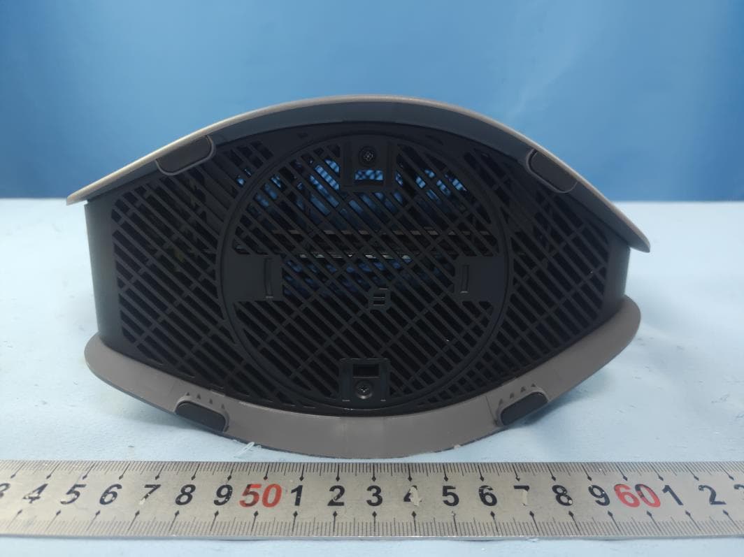
HDC17600021F1
Jul 31, 2021WiFi 5 Gigabit Router
Equipment Class
DSS - Part 15 Spread Spectrum Transmitter