HDC17600021F1WiFi 5 Gigabit Router
Adtran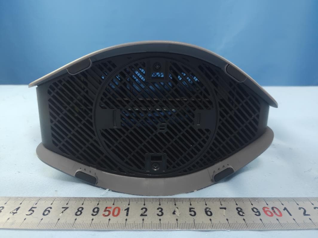
Click to zoom
Application Details
- Equipment Class
- DSS - Part 15 Spread Spectrum Transmitter
- Date of Grant
- Jul 31, 2021
- Application Purpose
- Original Equipment
- Date of Application
- Jul 31, 2021
- Equipment Note
- WiFi 5 Gigabit Router
- Frequency Range
- 2402.00000000 - 2480.00000000
- Company
- Adtran
- Country
- United States
Documents & Files
Document Text
Text extracted from the exhibit documents filed with the FCC. Open a document above to read the original.
Users Manual
Quick Start Overview The ADTRAN® 834-5 is a carrier-class Dual-Band Wi-Fi 5 Gigabit Ethernet router, built to deliver top-end Wi-Fi 5 performance, true gigabit routing throughput, and advanced service delivery capabilities. This quick start describes how to install ADTRAN’s 834-5 Home Gateway Unit. The 834-5 WiFi 5 Gigabit Router is an indoor gateway for delivering premium Gigabit services. ■ “Installing the 834-5 Gateway” on page 2 ■ “Understanding the Status LEDs” on page 4 ■ “Safety and Regulatory” on page 5 Figure 1 illustrates the front and back of the 834-5 gateway. Figure 1. Front and Back of the 834-5 Gateway (placeholder) WARNING! f Read all warning, cautions, notes and installation instructions before installing or servicing this equipment. f ATTENTION! Lisez tous les avertissements et mises en garde avant l’installation de cet équipement ou la réalisation de toute opération de maintenance f WARNING! f CAUTION! g NOTE WARNING indicates a hazard which, if not avoided, could result in death, injury or serious property damage. CAUTION indicates a hazard which, if not avoided, could result in service interruption, damage to the equipment, or minor property damage. NOTES inform the user of additional, but important, information or features. ADTRAN 834-5 Service Delivery Gateway Wi-Fi 5 Gigabit Router May 2021 617600021-13A P/N: 17600021F1 2617600139F1-13A Features The features of the 834-5 gateway include the following: ■1x Gigabit Ethernet (RJ-45) WAN interface ■ Subscriber interfaces ♦4x4 802.11ac @ 2.4GHz ♦ 4x4 802.11ac @ 5GHz ♦4x Gigabit Ethernet (RJ-45) LAN interfaces ♦1x USB 3.0 (Type A) Host port Installing the 834-5 Gateway The following are guidelines for basic installation of the 834-5. Package Contents ■ ADTRAN’s 834-5 WiFi 5 Gigabit Router ■ 12V DC power adapter Prior to Installation Before installing the equipment, inspect the gateway. If damage has occurred during shipping, file a claim with the carrier, and then contact ADTRAN Customer Support. For more information, refer to the product warranty available online at https://adtran/wp_support_warranty . Required Tools Standard technician tools and, if installing the gateway on a wall, a #2 Phillips-head screwdriver, are required for installing the 834-5. Mounting Options There are two options to install the 834-5: desktop and wall mount. Be sure to route and secure the fiber and cables in a manner that will prevent damage. These options are described below. Desktop Installation The 834-5 can be placed on a desk or table. The following table shows the recommended minimum distance (in feet and meters) between the gateway and household appliances to reduce interference. NOTE g Refer to the national, state and local electrical codes for the requirements for power, grounding, wiring, and installation methods. CAUTION! f The product is intended for indoor use only. Ethernet cables, and attached equipment are intended for use within the same building with equipotential bonding, and not intended to be placed in separate buildings or structures. Failure to deploy as described could result in permanent damage from lightning or other electrical events and voids the warranty. Furthermore, all connections from outside of the building, such as old POTS wiring, must be disconnected prior to use. Household ApplianceRecommended Minimum Distance (in feet and meters) Microwave ovens30 feet / 9 meters Baby monitor – analog20 feet / 6 meters Baby monitor – digital40 feet / 12 meters Cordless phone – analog20 feet / 6 meters 617600139F1-13A3 Wall Mount Installation The 834-5 can be mounted on a wall. Wall Mount Kit (17600192F1) can be ordered for mounting the 834-5. Instructions are provided in the related Quick Start Guide (617600192F1-13A). Connecting the 834-5 Gateway Figure 2 illustrates the installation (connection) options for the 834-5 gateway. Figure 2. 834-5 Gateway Installation Options (placeholder) The following subscriber connections are available on the rear of the 834-5: ■ 4x Gigabit Ethernet (RJ-45 Connectors) – LAN 1- 4 ports ■ 1x Gigabit Ethernet port (RJ-45 Connector) -WAN port ■ 4x4 802.11ax @ 2.4GHz ■ 4x4 802.11ax @ 5GHz ■ 1x USB 3.0 (Type A Connector) - port To connect the subscriber Ethernet interfaces, refer to Figure 2 and insert a Category 5E (or better) RJ-45 cable into one of the LAN ports (labeled LAN 1- 4) or the Gigabit Ethernet port (WAN) until there is an audible “click”. Connecting the Power Supply 1. Connect the end of the power adapter to the Power port on the rear panel of the gateway 2. Plug other end of the power adapter into the wall outlet. Cordless phone – digital 30 feet / 9 meters Bluetooth devices20 feet / 6 meters ZigBee20 feet / 6 meters WARNING! f Ensure that the 834-5 does not come in contact with water or other liquids. CAUTION! f Ensure that the 834-5 is not located in direct sunlight or next to any thermal obstructions. Household ApplianceRecommended Minimum Distance (in feet and meters) 4617600139F1-13A 3. Confirm that the power is connected properly. The Power LED should be lit on the front of the gateway. Resetting the Gateway A reset button is available if the 834-5 needs to be rebooted. To reboot the 834-5, press the Reset button on the rear panel of the gateway for 5 seconds or less. To reset the device to custom defaults, press the Reset button for 5 seconds or more. Understanding the Status LEDs The LEDs on the back panel of the 834-5 gateway enable you to monitor the device status. This section describes the three types of LEDs available on the 834-5 gateway. See Figure 3 for details. Figure 3. Status LEDs (placeholder) 2.4 GHz / 5 GHz Status LEDs The 2.4 GHz and 5 GHz status LEDs indicate the state of the wireless connections on the gateway. WPS Status LED The WPS status LED indicates the status of WPS (Wi-Fi protected setup). Product Specifications Electrical ■ Power is provided by a 12V DC Power Adapter that is included with the 834-5. The power adapter operates from a power sour…
Text truncated - open the document above for the full version.
Cover Letter(s)
Confidential Request Adtran Attention: Certification reviewer RE: Request for Confidentiality FCC ID: HDC17600021F1 To Whom It May Concern: Permanent Confidentiality [Complete this section if permanent confidentiality is requested] Request to withhold permanently from public review certain portions of the application for equipment certification for the referenced FCC identifiers. This request for confidentiality is made pursuant to 47 CFR 0.457(d) and 0.459 of the FCC Rules. In particular, the following sections of the application are to be kept permanently confidential: [Select one or more of items below, as appropriate] Schematics Block Diagrams Operational Description Tune-up Procedure Parts List Internal Photos (see note) Users Manual (see note) Note 1: Internal Photos may be held confidential 1) if the circuit board or internal components are not accessible to users. For example, it is acceptable if the circuit board is enclosed in epoxy. 2) Also, it is acceptable if the device is not accessible to the public, for example, a device mounted on the top of a large tower (or in a fenced enclosure) such that it is only serviceable by professional designated technicians under a Non-Disclosure Agreement (NDA). All sales for these devices must be under a NDA restricting the disclosure of the propriety information, including internal photos. Users Manual may be held confidential only when the manual contains proprietary technical information intended for professional technicians obligated under a NDA. All sales and distribution of the user’s manual must be under a NDA that restricts the disclosure of the information. In the application cover letter requesting permanent confidentiality the following additional description and the NDA exhibit is required: 1. Describe in detail how internal photos and/or users manual information are controlled to prevent them from becoming public or disclosed to unauthorized persons. 2. Describe how public access is restricted for products serviceable by professional designated technicians. 3. A statement that all sales of the non-consumer device will be under a NDA to include third party sales and that the final user of the device is subject to the NDA. 4. Provide an example of the NDA between the grantee and a purchaser. The request for confidentiality must Note 2: For scanning receiver, the schematics, block diagrams, operational description, tune-up procedure, parts list and internal photos are always held permanently confidential. Short-term Confidentiality [Complete this section if short-term confidentiality is requested] Request to withhold from public review for a period of [please enter 1 to 180] days from the date of the Grant of Equipment Authorization and prior to marketing, certain portions of the application for equipment certification for the referenced FCC identifiers. This request for confidentiality is made pursuant to 47 CFR 0.457(d) and 0.459 of the FCC Rules. In particular, the following sections of the application are to be kept short-term confidential for a period above from the date of the grant [Select one or more of items below that are not selected in the list above, as appropriate] Schematics Block diagrams Operational Description Tune-up Procedure Parts List Test Setup Photos External Photos Internal Photos Users Manual Rationale for request for confidentiality: We have invested considerable time and materials in research and development to produce the referenced product. Permanent confidentiality: Disclosure of the permanently confidential portions of this application to competitors would not only give them significant competitive advantages in developing similar products, but would also disclose successful implementation of unpublished, leading edge technology developed by us. Short-term confidentiality: Disclosure of the short-term confidential portions of this application during the period of importation and/or distribution would reveal key aspects of proprietary technology to competitors and diminish the value of our investment in research and development. If you have questions or need further information, please contact the undersigned. Sincerely, _________________ Dan Cassidy Mgr Compliance Engineering 2021-06-09
Cover Letter(s)
Letter of Agency Adtran [2021-06-09] Federal Communications Commission 445 12 th Street SW Washington, DC 20554 Subject: Limited Agency Agreement Adtran FCC ID: HDC17600021F1 To Whom It May Concern: We, (Adtran), hereby authorized William Chen of Intertek Testing Services to act as our Agent for the purpose of preparing application for FCC ID number HDC17600021F1 under all applicable parts of the FCC rules and regulations. The effective date of this limited agency agreement is (2021-06-09). The Limited Agency Agreement expires on (2022-06-09), unless sooner terminated or extended by written notice to Intertek Testing Services and the Federal Communications Commission. This is to advise that we are in full compliance with the Anti-Drug Abuse Act. The applicant is not subject to a denial of federal benefits pursuant to Section 5301 of the Anti-Drug Act of 1988, 21 U.S.C. 862, and no party to the application is subject to a denial of federal benefits pursuant to that section. If you have any questions or comments, please do not hesitate to contact me. Sincerely, Dan Cassidy Sr Mgr Compliance Engineering
External Photos
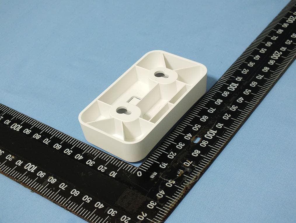
Page 1 of 3 TEST REPORT EXTERNAL PHOTO OF EUT Page 2 of 3 TEST REPORT Page 3 of 3 TEST REPORT
ID Label/Location Info
Remark Description EditorDate DATE: 1:1 1/1 / / N/A 1.彩色印刷,无边框; (Color printing,no frame) 2.材料: 50#亮白PET,UV油墨,背胶; (Material:50# Bright white PET ,with UV ink,adhesive) 3.原材料及后处理工艺均能满足我司《环保技术标准》要求. (Raw materials and the corresponding post processing should meet requirements defined in the T&W Environmental Protection Technical Standards) 2021-04-06 钱 敏 雷丹 标贴 6080000XXXXX Adtran 834-5 USA/CANADA 被贴物表面(在对应的方格填充黑色): 塑料面 塑料弧面铁机壳面/金属面 光油\覆膜彩盒 牛皮彩盒90度折角封口电源线180度对折角 电源/PLC产品高温其它() 牛皮盒\外箱光油彩盒90度折角封口 来料方式:卷装 V01 C9 M5 Y0 K60 Pantone Cool Gray 3 C 88.2 19.7
Internal Photos
Page 1 of 4 TEST REPORT INTERNAL PHOTO OF EUT Page 2 of 4 TEST REPORT Page 3 of 4 TEST REPORT Page 4 of 4 TEST REPORT
RF Exposure Info
FCC ID: HDC17600021F1 INTERTEK TESTING SERVICES RF Exposure The Equipment Under Test (EUT) is a WiFi 5 Gigabit Route which has Bluetooth and WiFi function, and WiFi operating at 2412-2462MHz for 802.11b/g/n-HT20, 11 channels with 5MHz channel spacing; 2422-2452MHz for 802.11n-HT40, 9 channels with 5MHz channel spacing; 5180 MHz - 5240 MHz & 5745MHz – 5825MHz for 802.11a/n/ac-HT20 with 21 channels; 5190 MHz ~ 5230 MHz & 5755MHz – 5795MHz for 802.11n/ac-HT40 with 9 channels and 5210 MHz & 5775MHz for 802.11ac-HT80 with 4 channel. The EUT was powered by 12Vdc via adapter (Input: AC100~240V, 50/60Hz, 1.0A, Output 12Vdc, 3.0A). The Device will automatically discontinue transmission in case of either absence of information to transmit or operational failure. There provisions are not intended to preclude the transmission of control or signalling information or the use of repetitive codes used by certain digital technologies to complete frame or burst intervals. For more detailed features description, please refer to the user’s manual. Bluetooth Version: 5.0 EDR mode. Antenna Type: Integral antenna. Antenna Gain: 4.0dBi. Modulation Type: GFSK, π/4DQPSK, 8DPSK. The nominal conducted output power specified: 4.0dBm (±3dB) Bluetooth Version: 5.0 BLE mode. Antenna Type: Integral antenna. Antenna Gain: 4.0dBi. Modulation Type: GFSK. The nominal conducted output power specified: 5.0dBm (±3dB) 2.4GHz WiFi: Antenna Type: Integral Antenna. Antenna Gain (Chain 1): 3.7dBi Antenna Gain (Chain 2): 4.7dBi Antenna Gain (Chain 3): 4.9dBi Antenna Gain (Chain 4): 4.7dBi Beamforming Gain:10.53 dBi Modulation Type: BPSK, QPSK, 16QAM, 64QAM, CCK, DQPSK, DBPSK and DSSS. The nominal conducted output power specified: 23dBm (Tolerance: ±5dB). 5GHz WiFi: Antenna Type: Integral Antenna. Antenna Gain (Chain 1): 4.8dBi Antenna Gain (Chain 2): 5.0dBi Antenna Gain (Chain 3): 4.2dBi Antenna Gain (Chain 4): 4.6dBi Beamforming Gain: 10.68 dBi Modulation Type: BPSK, QPSK, 16QAM, 64QAM and OFDM. The nominal conducted output power specified: 22dBm (Tolerance: ±8dB). FCC ID: HDC17600021F1 According to FCC Part 2.1091, this unlicensed transmitting devices is categorically excluded from routine environmental evaluation for RF exposure prior to equipment authorization or use, According to the KDB 447498 and OET 65, the simple calculation as below: For 5.0 DER mode The source-based time averaged maximum radiated power = 4+3+4= 11dBm = 12.59mW From above data, the exposed power density at a distance (R) of 20cm from the center of radiation of the antenna for 5.0 BLE mode can be calculated according to OET 65 as follow: = 12.59/ 4πR^2 = 0.003 mW/cm^2 For 5.0 BLE mode The source-based time averaged maximum radiated power = 5+3+4= 12dBm = 15.85mW From above data, the exposed power density at a distance (R) of 20cm from the center of radiation of the antenna for 5.0 BLE mode can be calculated according to OET 65 as follow: = 15.85/ 4πR^2 = 0.003 mW/cm^2 For 2.4GHz Band The source-based time averaged maximum radiated power in ANT 4 mode = 23+5+4.7= 32.7dBm = 1862.1mW From above data, the exposed power density at a distance (R) of 20cm from the center of radiation of the antenna for 2.4GHz band can be calculated according to OET 65 as follow: = 1862.1/ 4πR^2 = 0.37 mW/cm^2 For 5GHz Band The source-based time averaged maximum radiated power in ANT 3 mode = 22+8+4.2= 34.2dBm = 2630.3mW From above data, the exposed power density at a distance (R) of 20cm from the center of radiation of the antenna for 5GHz band can be calculated according to OET 65 as follow: = 2630.3mW/ 4πR^2 = 0.52 mW/cm^2 The MPE limit is 1.0 mW/cm^2 for general population and uncontrolled exposure in the Bluetooth frequency range according to FCC Part 1.1310. As the measured power density at 20cm from the transmitter is lower than the MPE limit, the compliance to the MPE limit can be ensured by indicating the minimum 20cm separation between the transmitter's radiating structure and body of the user or nearby persons. FCC ID: HDC17600021F1 INTERTEK TESTING SERVICES For Simultaneous transmitting of 2.4GHz WiFi and 5GHz WiFi, According to 865664D02 2.2 d) 1): The sum of the ratios of the spatially averaged results to the applicable frequency dependent MPE limits = 0.37/1 + 0.52/1 = 0.89 < 1 For Simultaneous transmitting of 2.4GHz WiFi and Bluetooth, According to 865664D02 2.2 d) 1): The sum of the ratios of the spatially averaged results to the applicable frequency dependent MPE limits = 0.37/1 + 0.003/1 = 0.373 < 1 For Simultaneous transmitting of 5GHz WiFi and Bluetooth, According to 865664D02 2.2 d) 1): The sum of the ratios of the spatially averaged results to the applicable frequency dependent MPE limits = 0.52/1 + 0.003/1 = 0.523< 1 For Simultaneous transmitting of 2.4GHz WiFi, Bluetooth and 5GHz WiFi, According to 865664D02 2.2 d) 1): The sum of the ratios of the spatially averaged results to the applicable frequency dependent MPE limits = 0.37/1 + 0.003/1 + 0.52/1 = 0.893< 1 Since the sum of the MPE ratios for all simultaneously transmitting antennas incorporated in the device is ≤ 1.0, the EUT is considered to satisfy MPE compliance for simultaneous transmission operations. The following RF exposure statement or similar sentence is proposed to be included in the user manual: “FCC RF Radiation Exposure Statement Caution: This Transmitter must be installed to provide a separation distance of at least 20 cm from all persons.”
Test Report
Adtran TEST REPORT SCOPE OF WORK FCC Testing – 834-5 REPORT NUMBER 210304050SZN-002 ISSUE DATE [REVISED DATE] 24 July 2021 [---------------------] PAGES 46 DOCUMENT CONTROL NUMBER FCC ID 247_b © 2017 INTERTEK Intertek Report No.: 210304050SZN-002 This report is for the exclusive use of Intertek's Client and is provided pursuant to the agreement between Intertek and its Client. Intertek's responsibility and liability are limited to the terms and conditions of the agreement. Intertek assumes no liability to any party, other than to the Client in accordance with the agreement, for any loss, expense or damage occasioned by the use of this report. Only the Client is authorized to permit copying or distribution of this report and then only in its entirety. Any use of the Intertek name or one of its marks for the sale or advertisement of the tested material, product or service must first be approved in writing by Intertek. The observations and test results in this report are relevant only to the sample tested. This report by itself does not imply that the material, product, or service is or has ever been under an Intertek certification program. Intertek Testing Service Shenzhen Ltd. Longhua Branch 101, 201, Building B, No. 308 Wuhe Avenue, Zhangkengjing Community, GuanHu Subdistrict, LongHua District, Shenzhen. Tel: (86 755) 8601 6288 Fax: (86 755) 8601 6751 Version: 01-November-2017 Page: 1 of 46 FCC ID 247_b TEST REPORT 101, 201, Building B, No. 308 Wuhe Avenue, Zhangkengjing Community, GuanHu Subdistrict, LongHua District, Shenzhen. Tel: (86 755) 8601 6288 Fax: (86 755) 8601 6751 www.intertek.com TEST REPORT Report No.: 210304050SZN-002 Product: WiFi 5 Gigabit Router Model No.: 834-5 Brand Name: ADTRAN FCC ID: HDC17600021F1 Applicant: Adtran 901 Explorer Boulevard, Huntsville, Alabama 35806-2807, United States Test Method(s)/ Standard(s): FCC Part 15 Subpart C; FCC KDB 558074 D01 v05r02 ANSI C63.10: 2013 Conclusion: The sample as received complied with the FCC Part 15 Subpart C requirement. Test By: Intertek Testing Services Shenzhen Ltd. Longhua Branch 101, 201, Building B, No. 308 Wuhe Avenue, Zhangkengjing Community, GuanHu Subdistrict, LongHua District, Shenzhen, P.R. China. Sample Receipt Date: 04 March 2021 Test Conducted Date: 3 June 2021 to 07 June 2021 Issue Date: 24 July 2021 Prepared and Checked by: Approved by: Jeff Liang Peter Kang Engineer Senior Technical Supervisor Intertek Report No.: 210304050SZN-002 Version: 01-November-2017 Page: 2 of 46 FCC ID 247_b TEST REPORT MEASUREMENT/TECHNICAL REPORT This report concerns (check one:) Original Grant X Class I Change Equipment Type: DSS - Part 15 Spread Spectrum Transmitter Deferred grant requested per 47 CFR 0.457(d)(1)(ii)? Yes No X If yes, defer until: date Company Name agrees to notify the Commission by: date of the intended date of announcement of the product so that the grant can be issued on that date. Transition Rules Request per 15.37? Yes No X If no, assumed Part 15, Subpart C for intentional radiator − the new 47 CFR [10-1-19 Edition] provision. Report prepared by: Winkey Wang Intertek Testing Services Shenzhen Ltd. Longhua Branch 101, 201, Building B, No. 308 Wuhe Avenue, Zhangkengjing Community, GuanHu Subdistrict, LongHua District, Shenzhen. Tel: (86 755) 8601 0684 Fax: (86 755) 8601 6661 Intertek Report No.: 210304050SZN-002 Version: 01-November-2017 Page: 3 of 46 FCC ID 247_b TEST REPORT Table of Contents 1.0 Summary of Test Results ...................................................................................................... 4 2.0 General Description .............................................................................................................. 5 2.1 Product Description ........................................................................................................... 5 2.2 Related Submittal(s) Grants ............................................................................................... 5 2.3 Test Methodology .............................................................................................................. 5 2.4 Test Facility ........................................................................................................................ 5 3.0 System Test Configuration .................................................................................................... 6 3.1 Justification ....................................................................................................................... 6 3.2 EUT Exercising Software ..................................................................................................... 6 3.3 Special Accessories............................................................................................................. 6 3.4 Equipment Modification .................................................................................................... 6 3.5 Measurement Uncertainty ................................................................................................. 7 3.6 Support Equipment List and Description ............................................................................ 7 4.0 Test Results ........................................................................................................................... 8 4.1 Radiated Test Result .......................................................................................................... 8 4.1.1 Field Strength Calculation ............................................................................................... 8 4.1.2 Radiated Emission Configuration Photograph ................................................................ 9 4.1.3 Radiated Emission .......................................................................................................... 9 4.1.4 Transmitter Spurious Emissions (Radiated) .................................................................. 12 4.2 Conducted Emission at Mains Terminal .................…
Text truncated - open the document above for the full version.
Test Setup Photos
Page 1 of 2 TEST REPORT RADIATED EMISSION TEST SET-UP Front View (Below 1GHz) Back View (Below 1GHz) Page 2 of 2 TEST REPORT Front View (Above 1GHz) Back View (Above 1GHz)
Contact Information
Applicant
Paul Stover(Manager Compliance Engineering)
Test Firm
Intertek Testing Services Shenzhen Ltd. Longhua BrHolly Ou
[email protected]+86 755 86140691
Technical Specifications
| # | Rule Parts | Frequency Range | Power Output |
|---|---|---|---|
| 1 | 15C | 2.40 GHz - 2.48 GHz | 4.70 mW |
Other Applications from Adtran
HDC-17600083
Jul 30, 2026WiFi 7 10G Router
Equipment Class
NII - Unlicensed National Information Infrastructure TX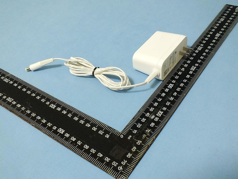
HDC-17600087
Apr 21, 2026WiFi 7 2.5G Router
Equipment Class
NII - Unlicensed National Information Infrastructure TX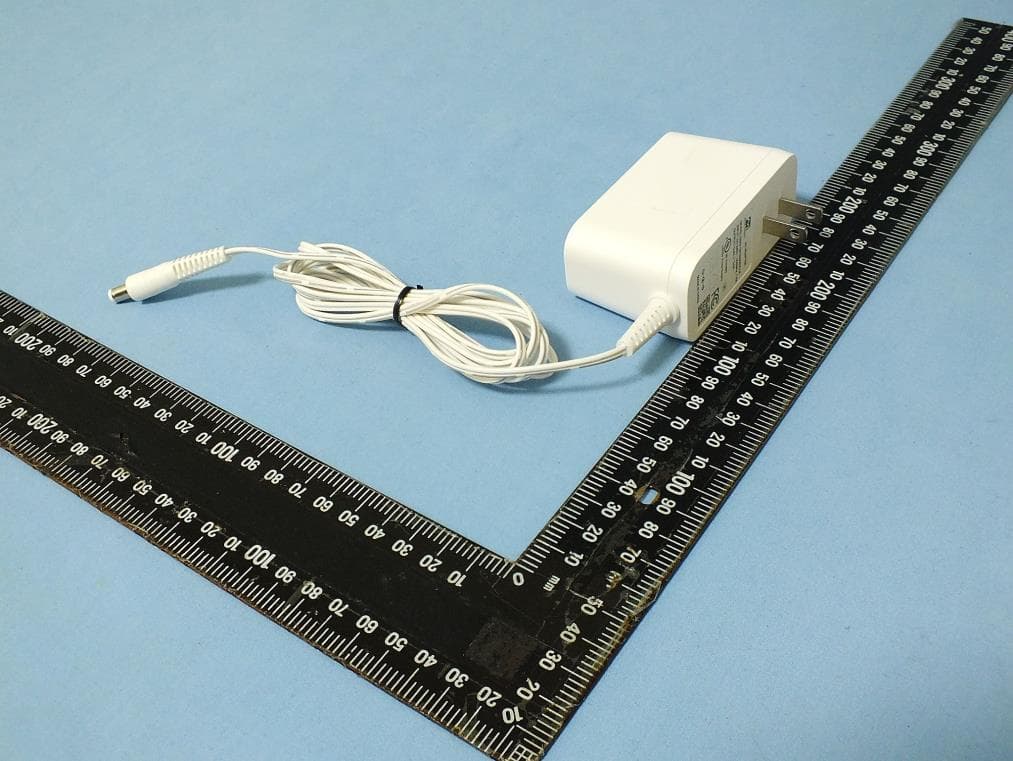
HDC-17600085
Mar 01, 2026WiFi 7 2.5G Router
Equipment Class
NII - Unlicensed National Information Infrastructure TXHDC-17600073
Jan 22, 2024WiFi 6E Mesh AP
Equipment Class
DTS - Digital Transmission System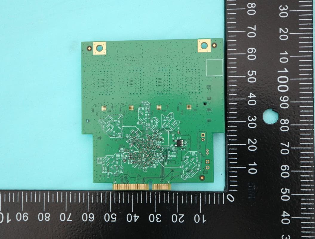
HDC-W349E0
Jan 19, 2021WiFi6 11ax wireless module
Equipment Class
NII - Unlicensed National Information Infrastructure TX