HDC1287562G1TOTAL ACCESS 324RG
Adtran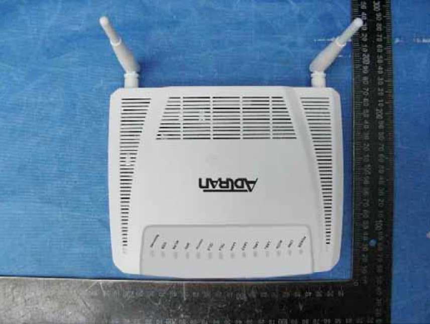
Click to zoom
Application Details
- Equipment Class
- DTS - Digital Transmission System
- Date of Grant
- May 24, 2014
- Application Purpose
- Original Equipment
- Date of Application
- May 20, 2014
- Equipment Note
- TOTAL ACCESS 324RG
- Frequency Range
- 2412.00000000 - 2462.00000000
- Company
- Adtran
- Country
- United States
Documents & Files
Document Text
Text extracted from the exhibit documents filed with the FCC. Open a document above to read the original.
Users Manual
jobAid 1 DESCRIPTION The Total Access 324RG Indoor 2 POTS + 4GigE (P/N 1287562G1) Home Gateway Optical Network Termination (ONT) provides Triple-Play services to a customer premises. The following is an illustration of the Home Gateway ONT. FEATURES The Indoor 2 POTS + 4GigE has the following features: Two POTS Interfaces Four Ethernet fiber interfaces with 1.244 Gigabits per second Upstream and 2.488 Gigabits per second downstream One Optical Interface AC Power Adapter USB Interface Voice Processing POTS uses in-band signaling tones and currents to determine call status (for example, call request). Because POTS allows for the transfer of audio signals below 3.3 kHz, POTS systems are also used for modems that allow data transmission (referred to as dial up connections). Ethernet Interface The Home Gateway ONT supports data service through four 10/ 100/1000Base-T Ethernet interfaces via an RJ-45-style connector. Reset Button WPS Data Encryption Button USB Interface Optical Interface Power Connection Power On/Off Ethernet Interfaces POTS Interfaces WLAN Button Total Access 324RG Indoor 2 POTS + 4GigE Home Gateway ONT Power The power feed is 12 VDC. INSTALLATION Before installing the Home Gateway ONT, inspect it for damage. If damage has occurred during shipping, file a claim with the carrier and then contact ADTRAN. For more information, refer to the warranty. Installation Guidelines The following are guidelines for this installation. WARNING ! Read all warnings and cautions before installing or servicing the Home Gateway ONT. Resetting the ONT A reset button is available if the Home Gateway ONT needs to be rebooted. To reset the Home Gateway ONT, insert a small pin into the RESET opening and hole the button down for 5 seconds or longer. WARNING ! All settings will return to Factory Defaults: Registration provisioning will be lost. Resetting the WLAN The Home Gateway ONT is equipped with a wireless local area network (WLAN) reset button. Refer to the illustration at the top of the first column for the button’s location. This is the WiFi link to other Internet devices. To reset the WLAN, press the WLAN button once. WPS Security The Home Gateway ONT is equipped with a WiFi Protected Setup (WPS) security button. This button is used to secure a wireless home network. However, there are security issues with this type of connection and ADTRAN does not recommend using this feature. Product P/N: 1287562G1 Issue Date: April 2014 Document P/N: 61287562G1-22A Documentation for ADTRAN Carrier Networks products is available for viewing and download directly from the ADTRAN Support Community website. Go to: https://supportforums.adtran.com/welcome Registration is required. ADTRAN offers training courses on our products, including customized training and courses taught at our facilities or at customer sites. For inquiries, go to: http://adtran.com/training The following documents provide additional information for this product: Total Access 5000 GPON OLT User Interface Guide Total Access 5000 Fiber to the Premises Deployment Guide Total Access 5000/5006 Engineering and Ordering Guide DRAFT 261287562G1-22A 1. Remove the POTS cable supplied with the Home Gateway ONT and connect one end to the Home Gateway ONT and the other end to a standard telephone base. 2. If a POTS cable is not available, select a standard telephone twisted pair cable of appropriate length and trim the insulation back approximately 1/2 inch on each end. 3. Refer to the illustration below and connect the twisted-pair Tip (green) and Ring (Red) to the RJ-11 connectors using an RJ-11 crimper. 4. Connect one end of the POTS cable to the Home Gateway ONT and the other end to a standard telephone connection. Step 3: Connect Ethernet The Home Gateway ONT supports four Gigabit (10/100/ 1000Base-T) connections. To install Ethernet to the Home Gateway ONT, refer to the illustration on the first page and complete the following steps: 1. Remove the Ethernet cable supplied with the Home Gate- way ONT and attach one end to the LAN1 connection on the rear of the Home Gateway ONT and the other end to the incoming Ethernet device. 2. If an Ethernet cable is not available, obtain a CAT5 or 6 cable of appropriate length and trim the insulation back approximately 1/2 inch on both ends. 3. Connect the wires per to an RJ-45 connector using the table below. 4. Crimp the connector using an RJ-45 Crimper. 5. Connect one end to the appropriate LAN1 connection on the rear of the Home Gateway ONT and the other end to the incoming Ethernet device. 6. Repeat these steps as necessary for each additional Ethernet connection required. Ethernet RJ-45 Pin-out PinNameDescriptionColor Code 1TRD0+Transmit/Receive PositiveWhite/Orange 2TRD0‐Transmit/Receive NegativeOrange 3TRD1+Transmit/Receive PositiveWhite/Green 4TRD2+Transmit/Receive PositiveBlue 5TRD2‐Transmit/Receive NegativeWhite/Blue 6TRD1‐Transmit/Receive NegativeGreen 7TRD3+Transmit/Receive PositiveWhite/Brown 8TRD3‐Transmit/Receive NegativeBrown 1 2 3 4 1 = Not Connected 2 = Tip 3 = Ring 4 = Not connected POTS Pin-Outs Installation Overview To install the Home Gateway ONT, complete the following steps: Step 1: Install Home Gateway ONT Step 2: Connect POTS Step 3: Connect Ethernet Step 4: Connect Fiber Step 5: Connect Power Step 6: Connect USB Required tools Standard technician tools and those listed below are required for installing the Home Gateway ONT: 3/32 inch screw driver for connecting Home Gateway ONT power RJ-45/RJ-11 crimper A telephony/data communication test set PON power meter with wavelength filtering Fiberscope or videoscope Two #8 Pan Head screws (1 inch or greater in length) Assorted tie wraps for securing cabling and wiring For fiber optic connections, the following are required: Fiber optical fusion splice tools ODC Fiber cleaning tool SC Fiber connector Installation Steps To install the Home Gateway ONT, refer to the illustration on the first page and complete the following …
Text truncated - open the document above for the full version.
Cover Letter(s)
Corporate Office 901 Explorer Blvd. Huntsville, AL 35806 U.S. Mail P.O. Box 140000 Huntsville, AL 35814-4000 Toll Free: 1 800 9ADTRAN Telephone: 256 963.8000 http://www.adtran.com 022311 – 6 Request for Confidentiality Date: _ April-01-2014_ Subject: Confidentiality Request for: _FCC ID:_HDC1287562G1__And IC: 2250A-1287562G1 Pursuant to FCC 47 CRF 0.457(d) and 0.459 and IC RSP-100, Section 10, the applicant requests that a part of the subject FCC application be held confidential. Type of Confidentiality Requested Exhibit Short Term Permanent Block Diagrams Short Term External Photos Short Term Permanent* 2 Internal Photos Short Term Permanent Operation Description/Theory of Operation Short Term Permanent Parts List & Placement/BOM Short Term Permanent Tune-Up Procedure Short Term Permanent Schematics Short Term Test Setup Photos Short Term Permanent* User’s Manual *Note: ______(Insert Explanation as Necessary)______ ADTRAN, Inc. has spent substantial effort in developing this product and it is one of the first of its kind in industry. Having the subject information easily available to "competition" would negate the advantage they have achieved by developing this product. Not protecting the details of the design will result in financial hardship. Permanent Confidentiality: The applicant requests the exhibits listed above as permanently confidential be permanently withheld from public review due to materials that contain trade secrets and proprietary information not customarily released to the public. Short-Term Confidentiality: The applicant requests the exhibits selected above as short term confidential be withheld from public view for a period of ___(specify number of days not to exceed 180) 3 ___ days from the date of the Grant of Equipment Authorization and prior to marketing. This is to avoid premature release of sensitive information prior to marketing or release of the product to the public. Applicant is also aware that they are responsible to notify ACB in the event information regarding the product or the product is made available to the public. ACB will then release the documents listed above for public disclosure pursuant to FCC Public Notice DA 04-1705. NOTE for Industry Canada Applications: The applicant understands that until such time that IC distinguishes between Short Term and Permanent Confidentiality, either type of marked exhibit above will simply be marked Confidential when submitted to IC. Sincerely, By:Manager, Compliance , Jeffrey W. Whitmire 2 - The asterisked items (*) require further justification before permanent confidentiality will be allowed. These also currently require review by the FCC under their Permit-But-Ask policy before the grant is issued and can delay completion of an application. Further justification should be added to the note above. One such example for a potted device would be: “The EUT is FULLY potted using a non-removable epoxy based material. Removal of potting material causes irreparable damage to internal circuitry. See photographs exhibits that outline the device before and after potting.” 3 - Please refer to http://acbcert.com/documents/misc-docs/Memo-Short-Term-Vs-Standard-Confidentiality.pdf for complete details.
Cover Letter(s)
Corporate Office 901 Explorer Blvd. Huntsville, AL 35806 U.S. Mail P.O. Box 140000 Huntsville, AL 35814-4000 Toll Free: 1 800 9ADTRAN Telephone: 256 963.8000 http://www.adtran.com Authority to Act as Agent Date: April-01-2014 American Certification Body, Inc. 6731 Whittier Avenue Suite C110 McLean, VA 22101 To Whom It May Concern: Intertek Shanghai is authorized to act on our behalf, until otherwise notified, for applications to American Certification Body, Inc. (ACB). We certify that we are not subject to denial of federal benefits, that includes FCC benefits, pursuant to Section 5301 of the Anti-Drug Abuse Act of 1988, 21 U.S.C. 862. Further, no party, as defined in 47 CFR 1.2002 (b), to the application is subject to denial of federal benefits, that includes FCC benefits. Thank you, Agency Agreement Expiration Date: ____Dec 30, 2014___ By: Jeff .Whitmire (Signature 1 ) (Print name) Title: Manager, Compliance On behalf of: _ADTRAN, Inc.__ ____________ (Company Name) Telephone: _256-963-8554 ______________ 1
Cover Letter(s)
DECLARATION OF CONFORMITY Per FCC Part 2 Section 2. 1077(a) The following equipment: Product Name : GPON ONT (Optical Network Terminal) Trade Name : Model Number : TOTAL ACCESS 324RG It’s herewith confirmed to comply with the requirements of FCC Part 15 Rules. Operation is subject to the following two conditions: (1) This device may not cause harmful interference, and (2) This device must accept any interference received, including interference that may cause undesired operation. The result of electromagnetic emission has been evaluated by QuieTek EMC laboratory (NVLAP Lab. Code : 200533-0 ) and showed in the test report. ( Report No. : 1440369R-ITUSP01V02) It is understood that each unit marketed is identical to the device as tested, and any changes to the device that could adversely affect the emission characteristics will require retest. The following importer / manufacturer is responsible for this declaration: Company Name Adtran,Inc. Company Address 901 Explorer Boulevard Huntsville,Alabama 35806 USA Telephone Facsimile : Person is responsible for marking this declaration: Name ( Full name ) Position / Title Date Legal Signature Compliance Manager April 30, 2014 Jeff .Whitmire
External Photos
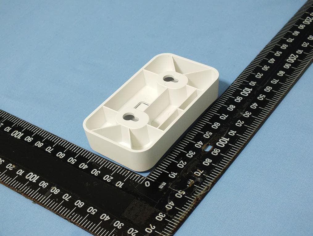
FCC ID: HDC1287562G1 IC: 2250A-1287562G1 Page 1 of 3 External Picture FCC ID: HDC1287562G1 IC: 2250A-1287562G1 Page 2 of 3 FCC ID: HDC1287562G1 IC: 2250A-1287562G1 Page 3 of 3 AC/DC Adapter
ID Label/Location Info
69.4±0.2mm 49.4±0.2mm 4-R2.2mm 1.3mm 1.1mm P/N: 1287562G1 TOTALACCESS 324RG Input: 12V 1.5A Made in China Serial Number: MACAddress: FCC ID: HDC1287562G1 IC: 2250A-1287562G1 Caution: This device complies with Part 15 of the FCC Rules / Industry Canada licence-exempt RSS standard(s). Operation is subject to the following two conditions: (1) this device may not cause harmful interference, and (2) this device must accept any interference received, including interference that may cause undesired operation. MODEL: Complies with 21CFR1040.10 and 21CFR1040.11 The label would be fixed on the device by skill screen.
Internal Photos
FCC ID: HDC1287562G1 IC: 2250A-1287562G1 Page 1 of 3 Internal Picture FCC ID: HDC1287562G1 IC: 2250A-1287562G1 Page 2 of 3 FCC ID: HDC1287562G1 IC: 2250A-1287562G1 Page 3 of 3
RF Exposure Info
FCC ID: HDC1287562G1 IC: 2250A-1287562G1 Page 1 of 2 Statement of compliance to Maximum Permissible Exposure (MPE) Applicant : Adtran, Inc. 901 Explorer Boulevard, Huntsville, Alabama, USA Manufacturer : Adtran, Inc. 901 Explorer Boulevard, Huntsville, Alabama, USA Equipment : GPON (Optional Network Terminal) Type/Model : TOTAL ACCESS 324RG Trade Name : According to §2.1091, §2.1093 and §1.1307(b), systems operating under the provisions of this section shall be operated in a manner that ensures that the public is not exposed to radio frequency energy level in excess of the Commission’s guidelines. The S = PG / (4πR²) Where S = power density in mW/cm² P = transmit power in mW G = numeric gain of transmit antenna R = distance (cm) R is chosen to be 20cm, the gain of antenna G = 3.00dBi = 1.995 As we can see from the test reports 140300791SHA-001: The maximum output power for Wi-Fi = 19.74dBm=94.189mW The MPE of Wi-Fi = PG / (4πR²) = 94.189 * 1.995 / (4 * 3.14 * 20 * 20) = 0.037 This level is below the MPE test exclusion requirements (≤1.0). Date of issue: April 25, 2014 Prepared by: Reviewed by: Wakeyou Wang (Project Engineer) Daniel Zhao (Reviewer) FCC ID: HDC1287562G1 IC: 2250A-1287562G1 Page 2 of 2 Appendix I Definition below must be outlined in the User Manual: To satisfy FCC RF exposure requirements, a separation distance of 20 cm or more should be maintained between the antenna of this device and persons during device operation. To ensure compliance, operations at closer than this distance is not recommended.
Test Report
FCC ID: HDC1287562G1 IC: 2250A-1287562G1 Page 1 of 87 EMC TEST REPORT for Intentional Radiator (Wi-Fi Function) No. 140300791SHA-001 Applicant : Adtran, Inc. 901 Explorer Boulevard, Huntsville, Alabama, USA Manufacturer : Adtran, Inc. 901 Explorer Boulevard, Huntsville, Alabama, USA Equipment : GPON (Optional Network Terminal) Type/Model : TOTAL ACCESS 324RG Trade Name : SUMMARY The equipment complies with the requirements according to the following standard(s): 47CFR Part 15 (2013): Radio Frequency Devices ANSI C63.4 (2003): American National Standard for Methods of Measurement of Radio-Noise Emissions from Low-Voltage Electrical and Electronic Equipment in the Range of 9 kHz to 40 GHz RSS-210 Issue 8 (December 2010): Low-power Licence-exempt Radiocommunication Devices (All Frequency Bands): Category I Equipment RSS-Gen Issue 3 (December 2010): General Requirements and Information for the Certification of Radiocommunication Equipment Date of issue: April 25, 2014 Prepared by: Reviewed by: Wakeyou Wang (Project Engineer) Daniel Zhao (Reviewer) FCC ID: HDC1287562G1 IC: 2250A-1287562G1 Page 2 of 87 Description of Test Facility Name: Intertek Testing Services Limited Shanghai Address: Building 86, No. 1198 Qinzhou Rd., North, Shanghai 200233, P.R. China FCC Registration Number: 236597 IC Assigned Code: 2042B-1 Name of contact: Jonny Jing Tel: +86 21 61278271 Fax: +86 21 54262353 FCC ID: HDC1287562G1 IC: 2250A-1287562G1 Page 3 of 87 Content SUMMARY .......................................................................................................................................................... 1 DESCRIPTION OF TEST FACILITY ......................................................................................................................... 2 1. GENERAL INFORMATION ............................................................................................................................ 4 1.1 Applicant Information ..................................................................................................... 4 1.2 Identification of the EUT ................................................................................................ 4 1.3 Technical specification ................................................................................................... 5 1.4 Mode of operation during the test / Test peripherals used .............................................. 5 2. TEST SPECIFICATION .................................................................................................................................. 6 2.1 Instrument list ................................................................................................................. 6 2.2 Test Standard .................................................................................................................. 6 2.3 Test Summary ................................................................................................................. 7 2.4 Data rate VS power ......................................................................................................... 8 3. MINIMUM 6DB BANDWIDTH ....................................................................................................................... 9 3.1 Limit ................................................................................................................................ 9 3.2 Test Configuration .......................................................................................................... 9 3.3 Test Procedure and test setup .......................................................................................... 9 3.4 Test Protocol ................................................................................................................. 10 4. MAXIMUM PEAK OUTPUT POWER ............................................................................................................. 24 4.1 Test limit ....................................................................................................................... 24 4.2 Test Configuration ........................................................................................................ 24 4.3 Test procedure and test setup ........................................................................................ 24 4.4 Test protocol ................................................................................................................. 25 5. POWER SPECTRUM DENSITY ..................................................................................................................... 27 5.1 Test limit ....................................................................................................................... 27 5.2 Test Configuration ........................................................................................................ 27 5.3 Test procedure and test setup ........................................................................................ 27 5.4 Test Protocol ................................................................................................................. 28 6. RADIATED EMISSION ................................................................................................................................. 42 6.1 Test limit ....................................................................................................................... 42 6.2 Test Configuration ........................................................................................................ 42 6.3 Test procedure and test setup ........................................................................................ 43 6.4 Test protocol ................................................................................................................. 44 7. EMISSION OUTSIDE THE FREQUENCY BAND ............................................................................................. 49 7.1 Limit ....................…
Text truncated - open the document above for the full version.
Test Setup Photos
FCC ID: HDC1287562G1 IC: 2250A-1287562G1 Page 1 of 3 Test Setup FCC ID: HDC1287562G1 IC: 2250A-1287562G1 Page 2 of 3 1. Radiated Emission 30MHz-1000MHz FCC ID: HDC1287562G1 IC: 2250A-1287562G1 Page 3 of 3 Higher than 1GHz
Contact Information
Applicant
Paul Stover(Manager Compliance Engineering)
Technical Contact
Intertek Testing Services Limited ShanghaiWakeyou Wang
[email protected]86 21 61278448
Building No.86, 1198 Qinzhou Road(North) · Shanghai · China
Test Firm
Intertek Testing Services Limited ShanghaiJonny Jing
Technical Specifications
| # | Rule Parts | Frequency Range | Power Output |
|---|---|---|---|
| 1 | 15C | 2.41 GHz - 2.46 GHz | 94.00 mW |
Other Applications from Adtran
HDC-17600083
Jul 30, 2026WiFi 7 10G Router
Equipment Class
NII - Unlicensed National Information Infrastructure TX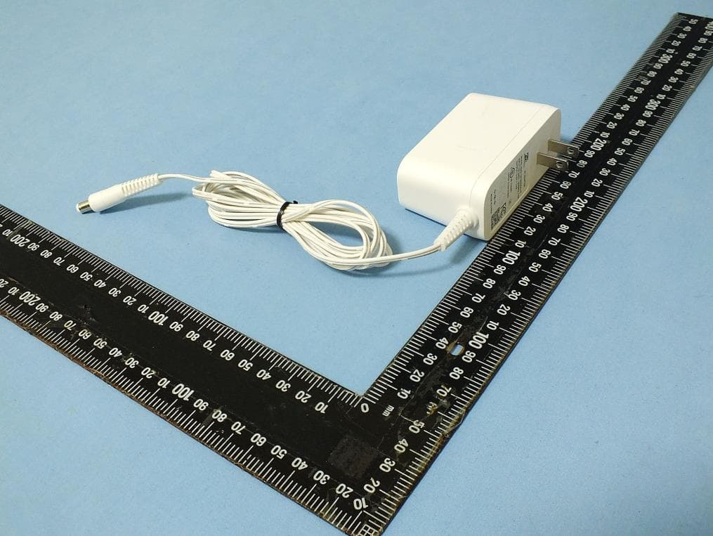
HDC-17600087
Apr 21, 2026WiFi 7 2.5G Router
Equipment Class
NII - Unlicensed National Information Infrastructure TX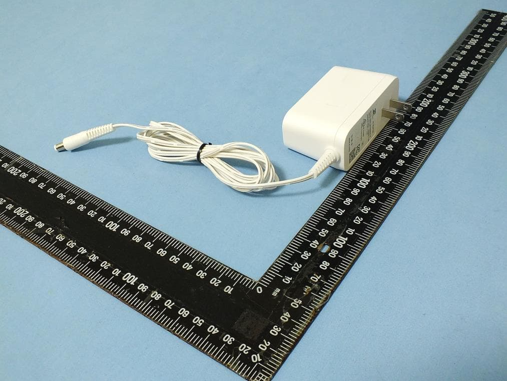
HDC-17600085
Mar 01, 2026WiFi 7 2.5G Router
Equipment Class
NII - Unlicensed National Information Infrastructure TXHDC-17600073
Jan 22, 2024WiFi 6E Mesh AP
Equipment Class
DTS - Digital Transmission System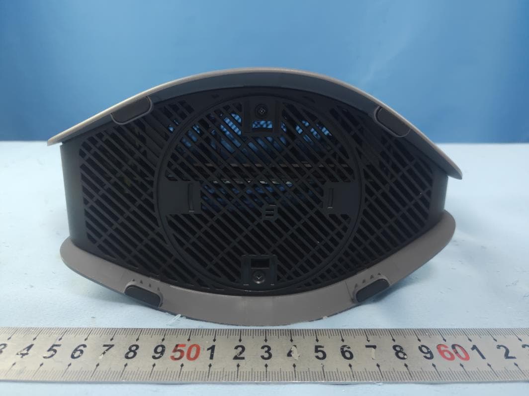
HDC17600021F1
Jul 31, 2021WiFi 5 Gigabit Router
Equipment Class
DSS - Part 15 Spread Spectrum Transmitter