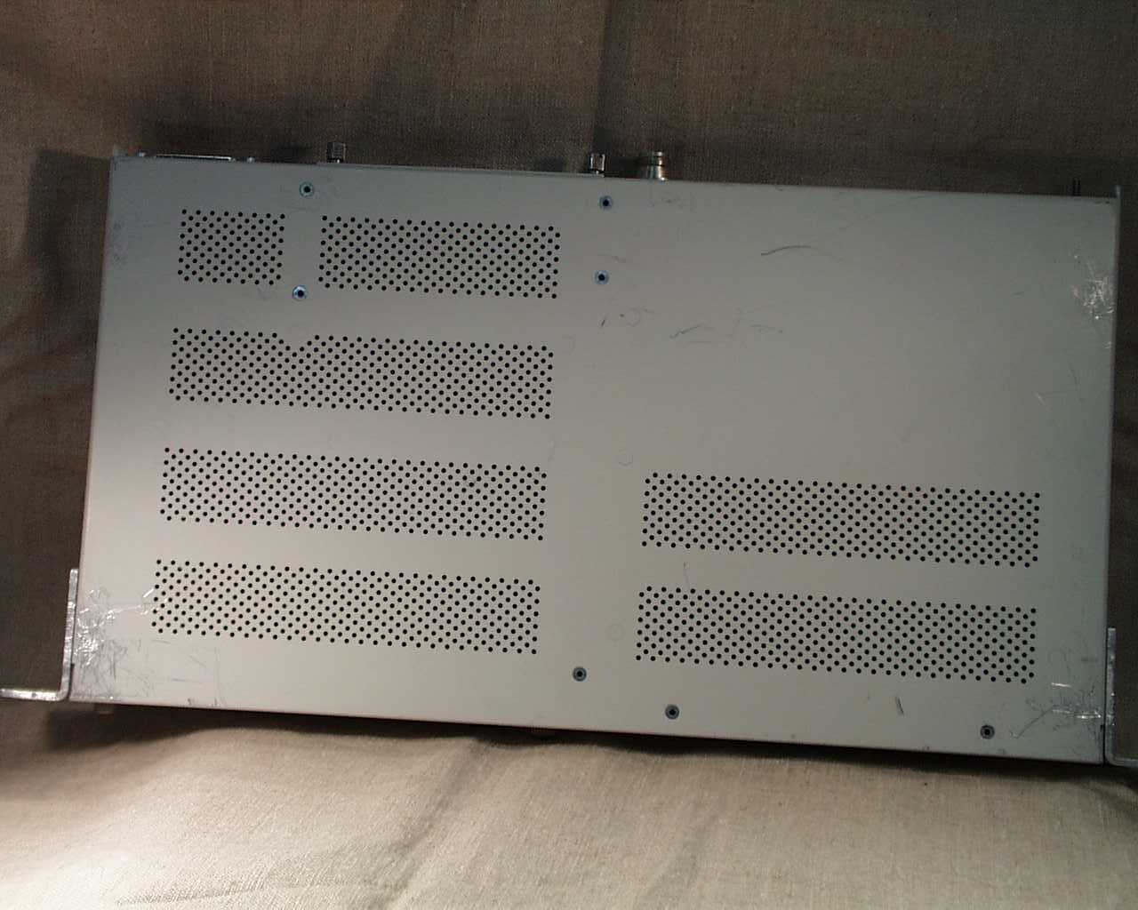
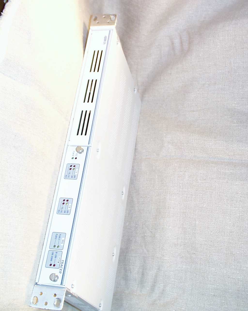
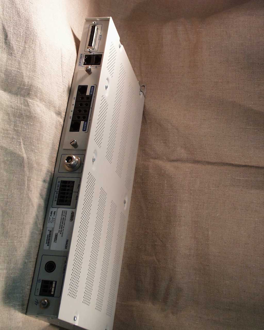
HDCTRACERL9Point-to-point spread spectrum communications syst
Adtran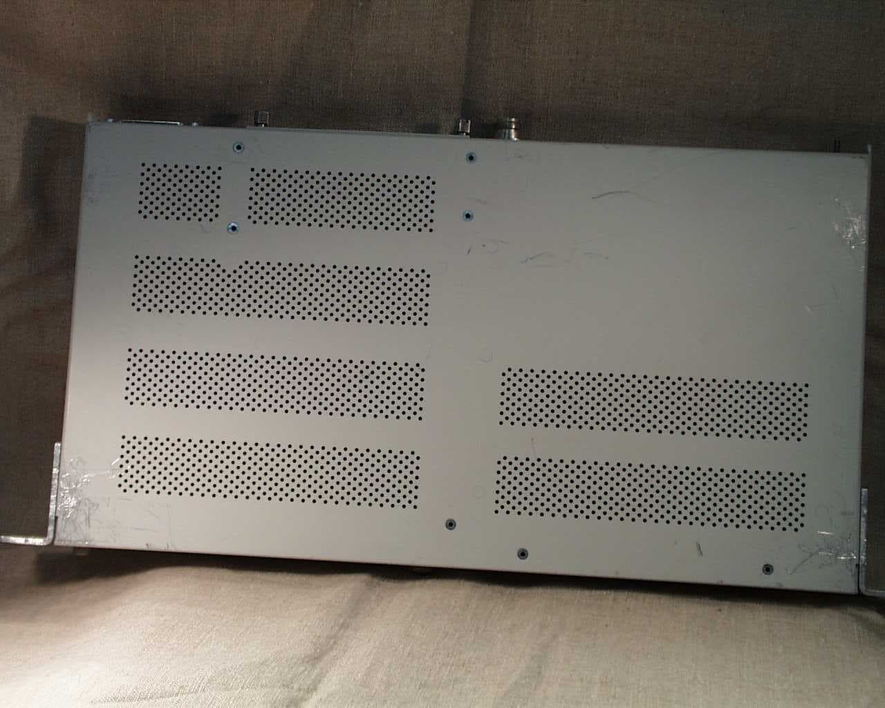
Click to zoom
Application Details
- Equipment Class
- DSS - Part 15 Spread Spectrum Transmitter
- Date of Grant
- Jan 04, 2001
- Application Purpose
- Original Equipment
- Date of Application
- Nov 28, 2000
- Equipment Note
- Point-to-point spread spectrum communications syst
- Frequency Range
- 2400.00000000 - 2483.50000000
- Company
- Adtran
- Country
- United States
Documents & Files
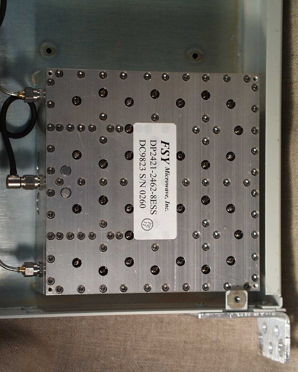
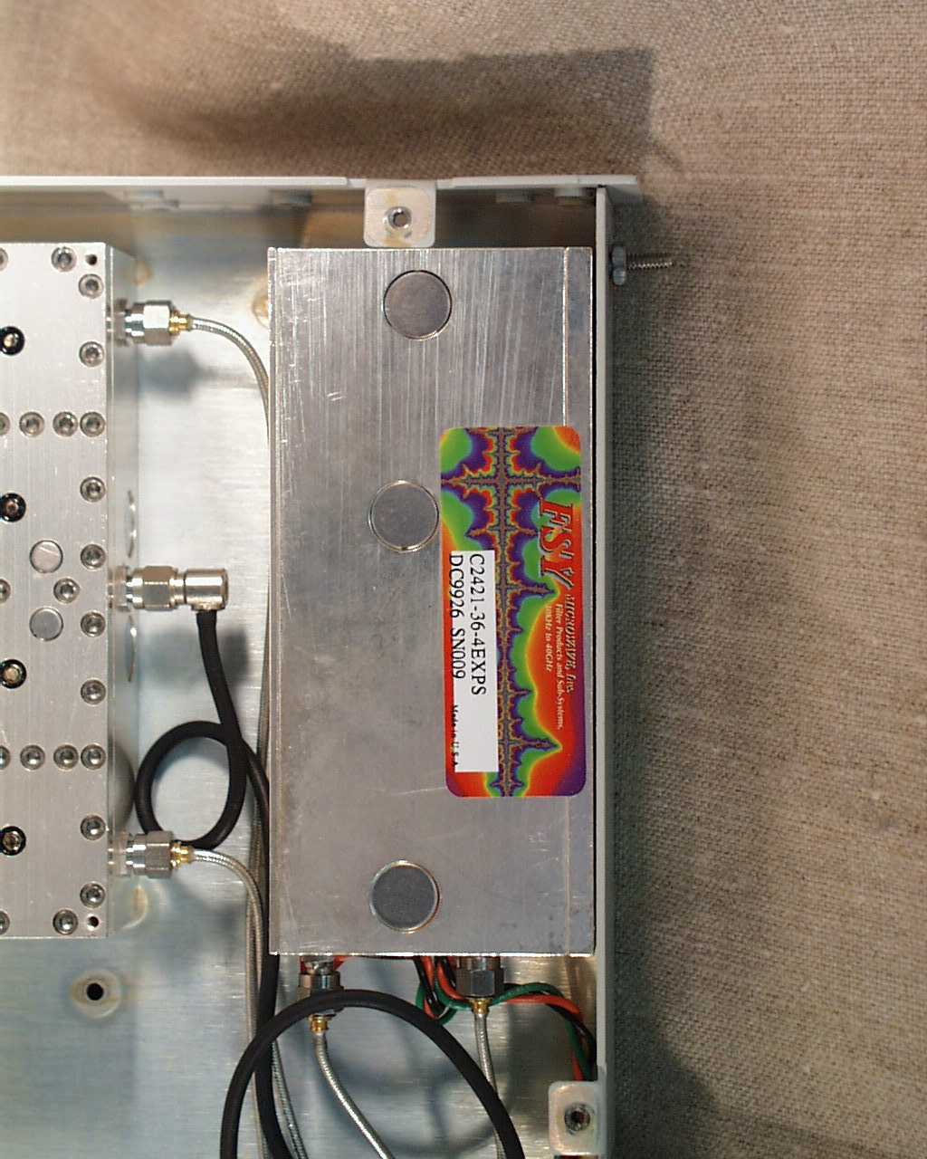
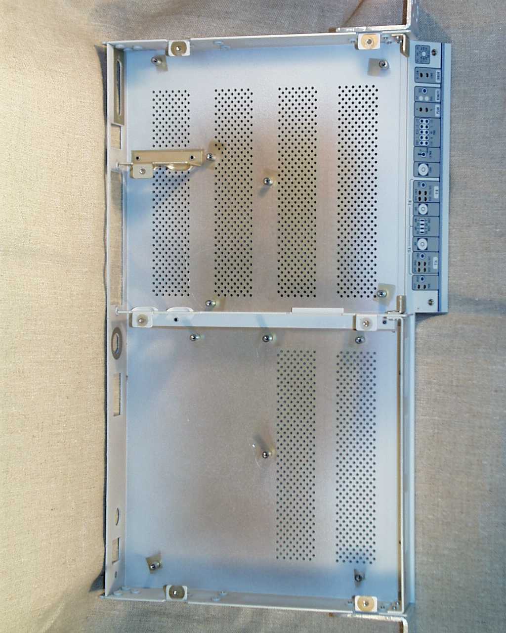
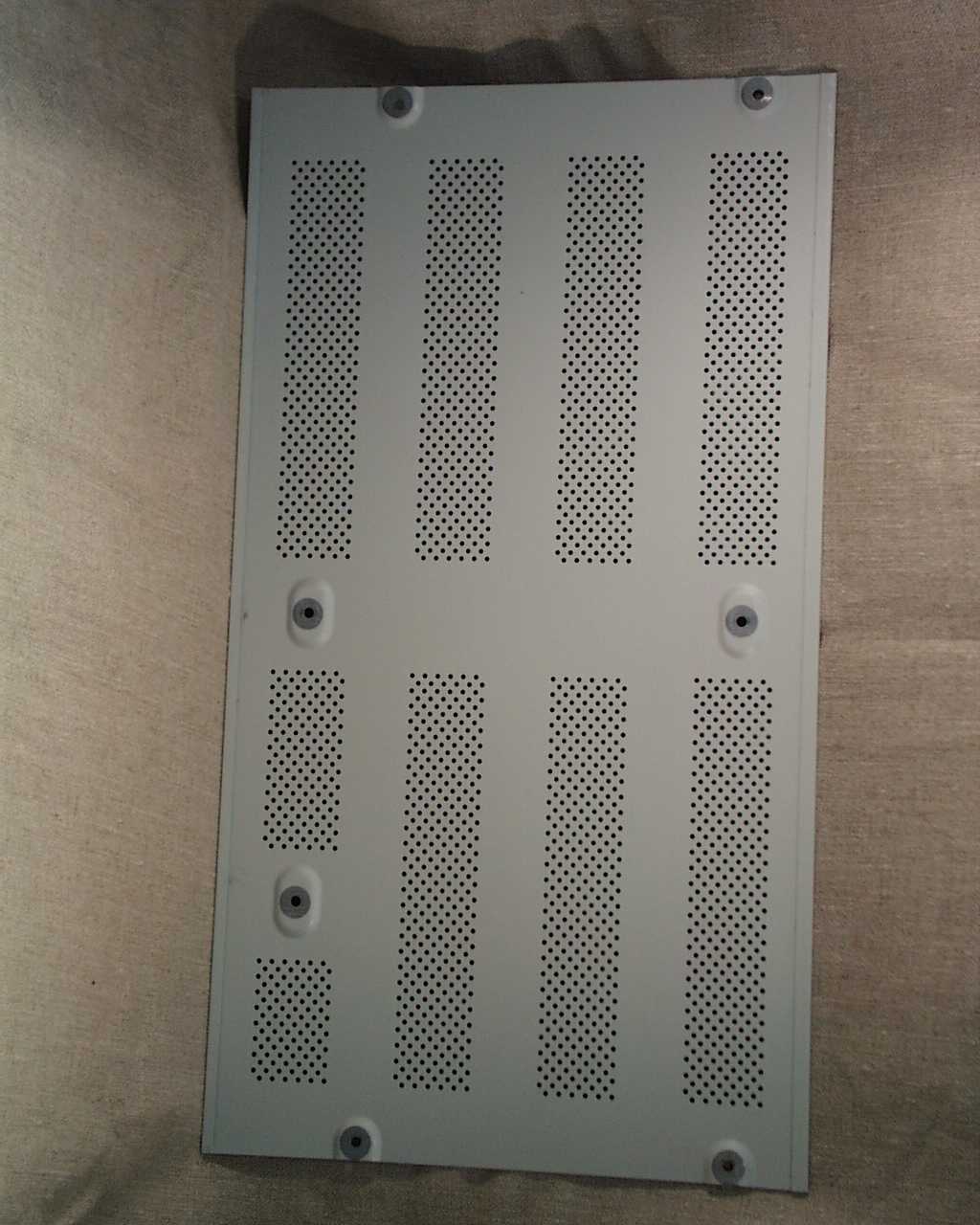
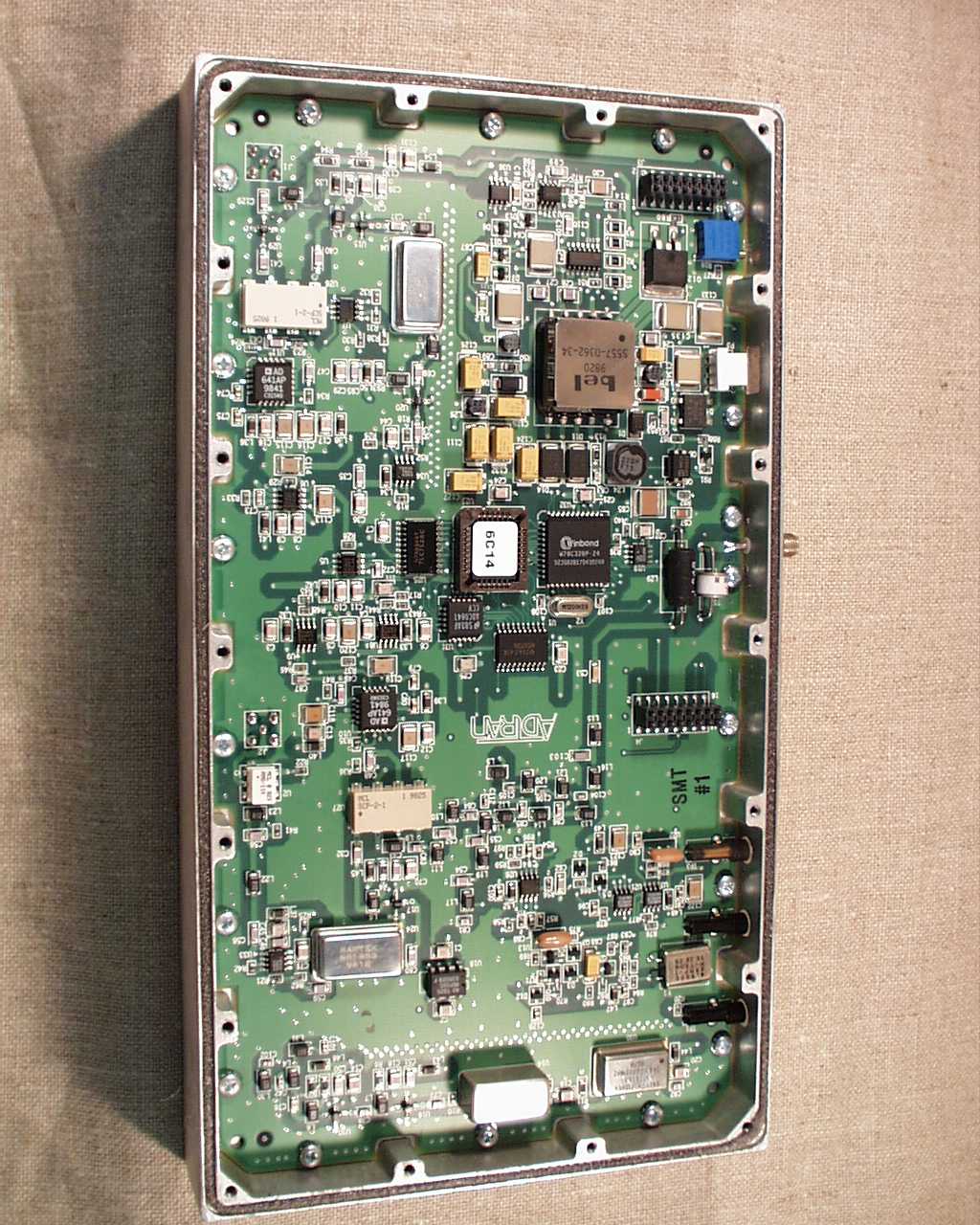
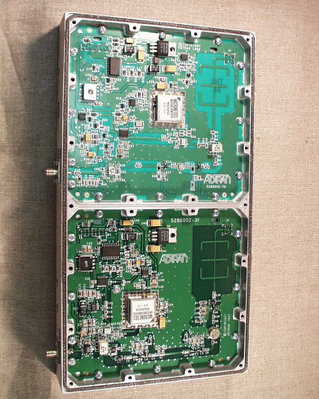
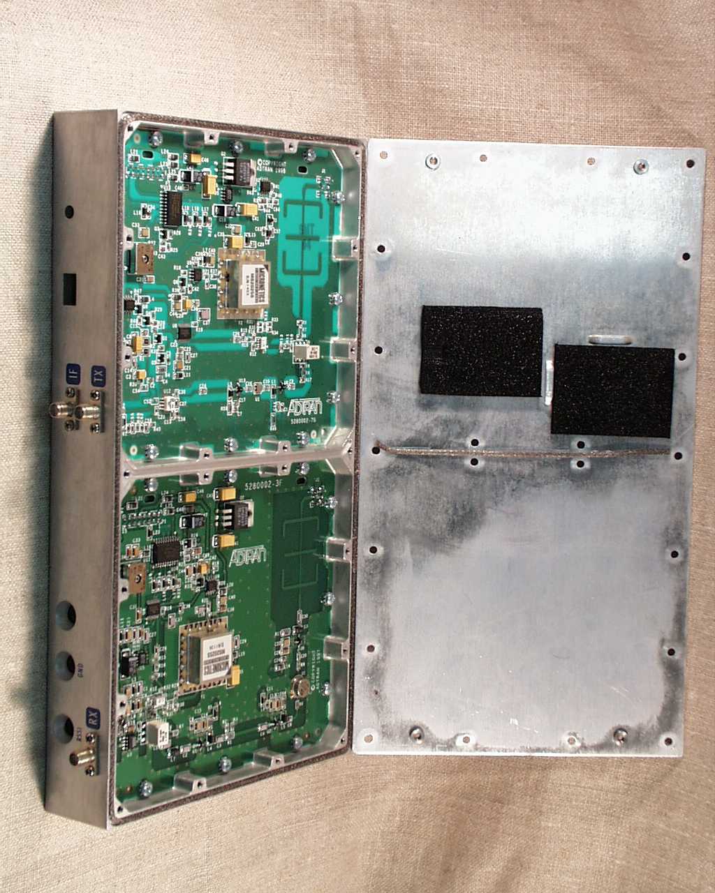
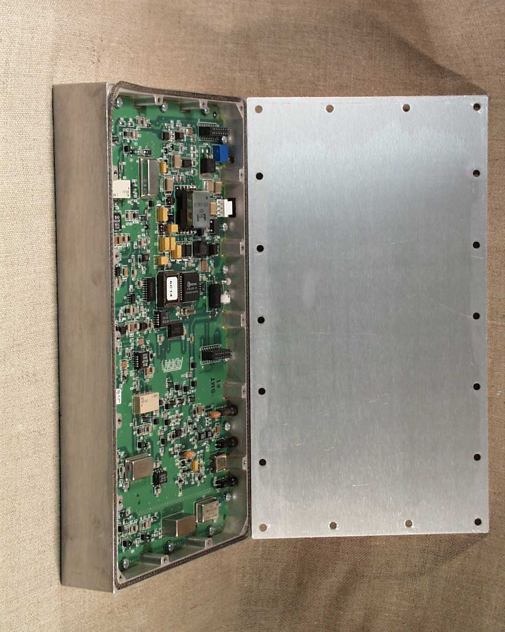
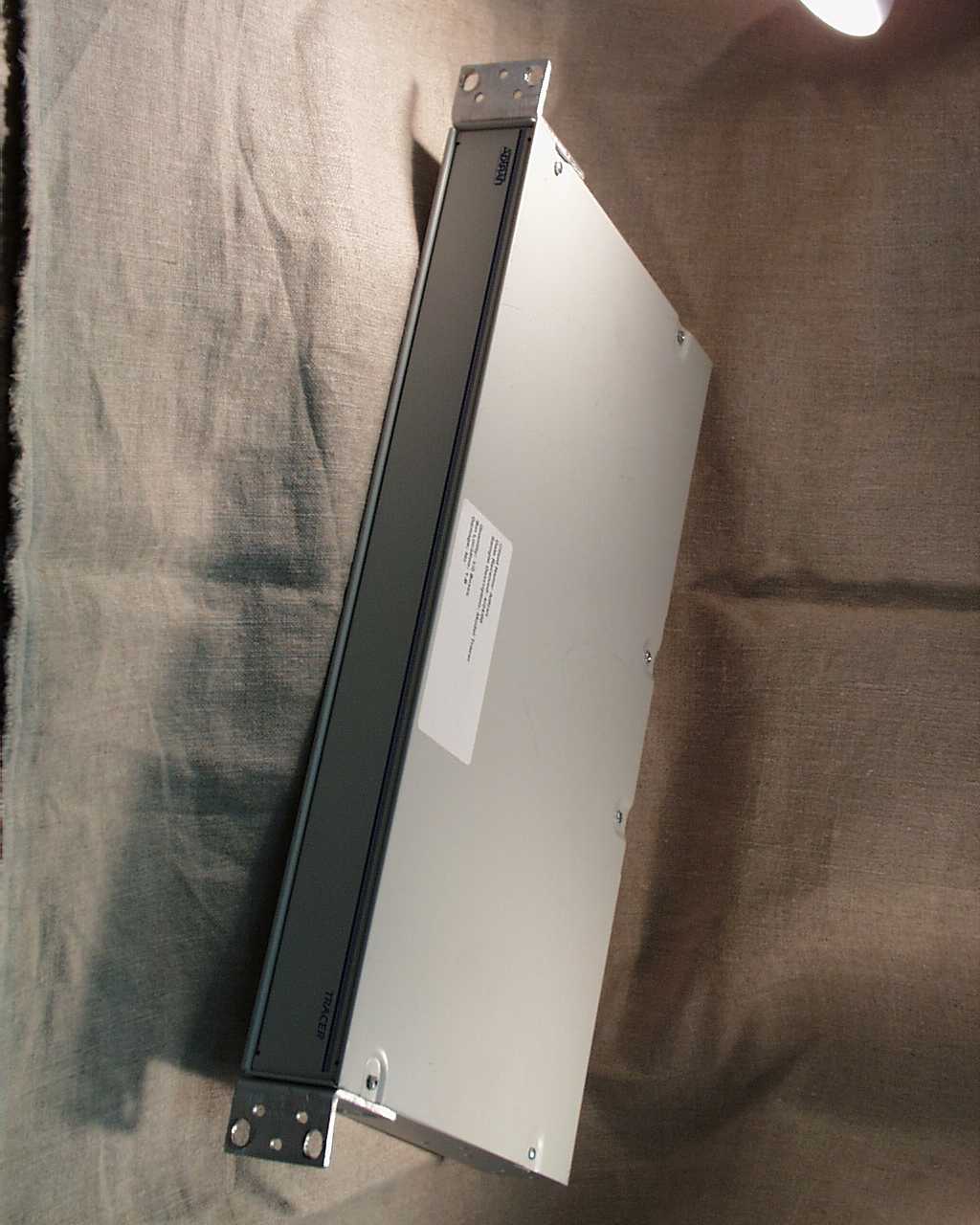
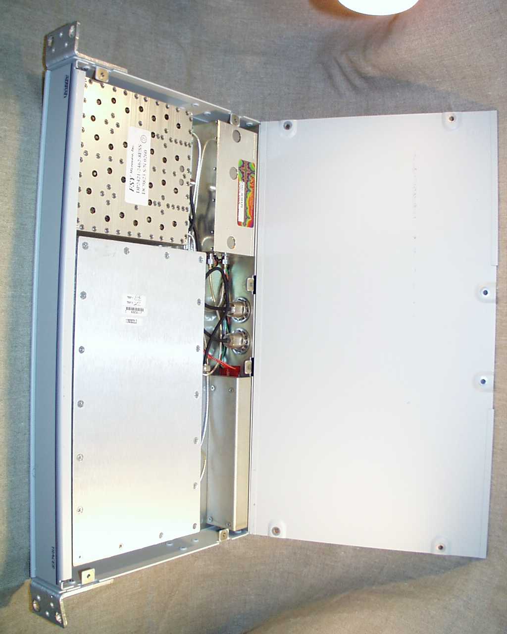
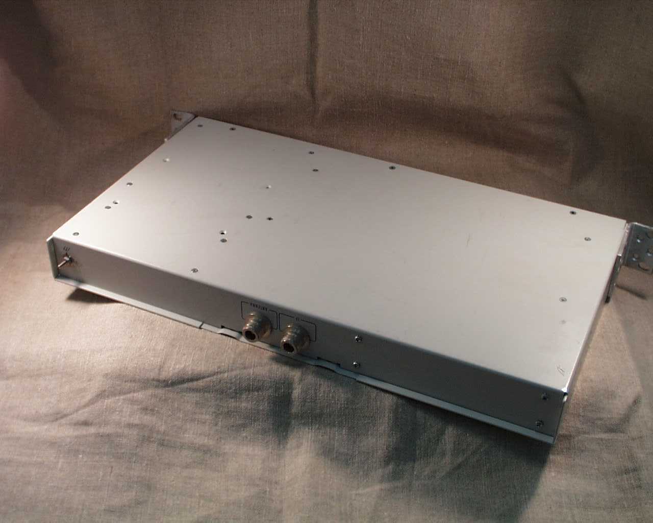
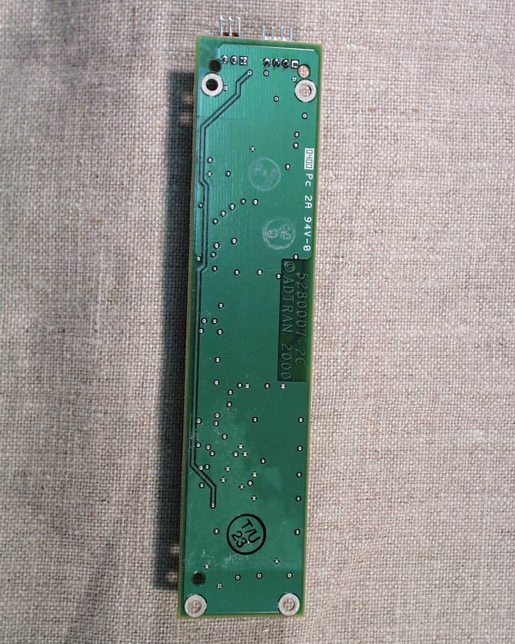
Document Text
Text extracted from the exhibit documents filed with the FCC. Open a document above to read the original.
Users Manual
A ADTRAN, Inc. M/N: 4280TRACERT1L9-A and 4280TRACERT1L9-B FCC ID: HDCTRACERL9 Instruction Manual The following pages contain a preliminary copy of the User’s Manual for the TRACER. ADTRAN, Inc. respectfully requests that this information be withheld from public inspection. TRACER 2xT1 User’s Manual61280003L2-1B Preliminary TRACER ® 2xT1 User’s Manual 61280003L2-1BTRACER 2xT1 User’s Manual Preliminary This equipment has been tested and found to comply with the limits for an intentional radiator, pursuant to Part 15, Subpart C of the FCC Rules. This equipment generates, uses, and can radiate radio frequency energy. If not installed and used in accordance with the instructions, it may cause interference to radio communications. The limits are designed to provide reasonable protection against such interference in a residential situation. However, there is no guarantee that interference will not occur in a particular installation. If this equipment does cause interference to radio or television reception, which can be determined by turning the equipment on and off, the user is encouraged to try to correct the interference by one or more of the following measures: •Reorient or relocate the receiving antenna of the affected radio or television. •Increase the separation between the equipment and the affected receiver. •Connect the equipment and the affected receiver to power outlets on separate circuits. •Consult the dealer or an experienced radio/TV technician for help. W A R N I N G Changes or modifications not expressly approved by ADTRAN could void the user’s authority to operate the equipment. Shielded Cables A shielded-type power cord is required in order to meet FCC emission limits and also to prevent interference with nearby radio and television reception when using the AC voltage adapter. It is essential that only the Adtran-provided power cord be used. FCC Output Power Restrictions The FCC does not require licensing to implement this device. However, the FCC has established restrictions regarding maximum output power and the adjustments required when employing directional gain antennas. (Refer to “Setting the Transmitter Power” in Section 2 of this manual). These restrictions are detailed in FCC Part 15.247 (b)(1), (b)(3)(i), and (3)(iii). It is the responsibility of the individuals designing and implementing the radio system to assure compliance with these and any other pertinent FCC Rules and Regulations. This device must be professionally installed. Exposure to Radio Frequency Fields The TRACER is designed in three versions with the following power options: 2.4 GHz @ 100 mw 2.4 GHz @ 1 w 5.8 GHz @100 mw These levels of RF energy in are below the Maximum Permissible Exposure (MPE) levels specified in FCC OET 65:97-01. The installation of high gain antenna equipment in the system configuration may create the opportunity for exposure to levels higher than recommended for the general population at a distance less than one meter from the center of the antenna. The following precautions must be taken during installation of this equipment: RADIO FREQUENCY INTERFACE STATEMENT TRACER 2xT1 User’s Manuali Preliminary TRACER 2xT1 User’s Manual 61280003L2-1B Radio Frequency Interference Statement ii Preliminary •The installed antenna must not be located in a manner that allows exposure of the general population to the direct beam path of the antenna at a distance less than one meter. Installation on towers, masts, or rooftops not accessible to the general population is recommended; or •Mount the antenna in a manner that prevents any personnel from entering the area within one meter from the front of the antenna. •It is recommended that the installer place radio frequency hazard warnings signs on the barrier that prevents access to the antenna. •Prior to installing the antenna to the RFC output, make sure the power is adjusted to the settings specified in section 2 of this manual. •During antenna installation, be sure that power to the TRACER equipment is turned off in order to prevent any energy presence on the coaxial connector. •During installation and alignment of the antenna, do not stand in front of the antenna assembly. •During installation and alignment of the antenna, do not handle or touch the front of the antenna. These simple precautions must be taken to prevent general population and installation personnel from exposure to RF energy in excess of specified MPE levels. TRACER 2xT1 User’s Manual 61280003L2-1B Table of Contents iii Preliminary Page Section 1 TRACER Description Introduction .................................................................................................................................1 ISM Band Spread Spectrum........................................................................................................1 NEBS...........................................................................................................................................1 Applications.................................................................................................................................2 Spread Spectrum..........................................................................................................................2 Direct Sequence.........................................................................................................2 Coding.......................................................................................................................2 Channel Selection........................................................................................................................3 Forward Error Correction............................................................................................................3 T1 Operation..............................................................................................................3 Framing....................................................................................…
Text truncated - open the document above for the full version.
Block Diagram
A ADTRAN, Inc. M/N: 4280TRACERT1L9-A and 4280TRACERT1L9-B FCC ID: HDCTRACERL9 Technical Specifications The following pages contain the technical specifications for the Rackmount TRACER with 1 Watt option as provided by ADTRAN, Inc. Included in the specifications is an RF block diagram. ADTRAN, Inc. respectfully requests that this information be withheld from public inspection. Specification Number74280.TRACT1L9-1A Revision A1 of 22 Tracer - Rack Configuration With 1 Watt Option PRODUCT SPECIFICATION APPROVALS: Engineering Manager:___________________________ Paul Nelson Product Manager:___________________________ Dan Pritchett Responsible Engineer:___________________________ Tony Goodloe RevisionDateECO#Comments Specification Number74280.TRACT1L9-1A Revision A2 of 22 Introduction Overview The Tracer provides dual T1 transport via a spread spectrum microwave link for distances over 20 miles. System performance is determined, in part, by the engineering of the microwave link. Each end of a Tracer link is comprised of two units - the baseband processor and the radio frequency converter (RFC). The DS-1 (T1) interfaces are provided on the rear of the baseband processor, which is mounted in a nineteen inch rack. The DS-1 interface provides connections up to 6000 feet from T1 equipment. The radio frequency converter can be rack-mounted adjacent to the baseband processor or, for higher system performance, can be mounted in a weather-tight enclosure adjacent to the antenna. A single coaxial cable connects the baseband processor to the RFC and another coaxial cable connects the RFC to the antenna. ISM Band Spread Spectrum The Federal Communications Commission (FCC) has established several portions of the radio frequency (RF) spectrum for use in Industrial, Scientific, and Medical (ISM) applications. Part 15.247 of the FCC rules describes the requirements of systems that operate in these bands. The three bands set aside are 902-928 MHz, 2400-2483.5 MHz, and 5725-5850 MHz and are designated for use only by spread spectrum transmitters, either frequency hopping or direct sequence. The Tracer operates in the 2400 - 2483.5 MHz band using direct sequence spread spectrum transmission. Applications Any application which would typically use metallic T1 as a transport can use Tracer instead. Figure 1 illustrates a typical application. Baseband Processor PBX Channel Bank RFCRFC Baseband Processor Channel Bank PBX Figure 1 Specification Number74280.TRACT1L9-1A Revision A3 of 22 In addition to telephony applications, uses in data communications, such as internetworking, video conferencing, and telemetry are possible. In short, any requirement for sharing data at a high rate is an application in which Tracer can be put to use. Spread Spectrum Spread spectrum is a form of communication in which the bandwidth of a message signal is intentionally increased, or spread. The FCC allows two methods of spreading - frequency hopping and direct sequence. Frequency Hopping A frequency hopping transmitter shifts the carrier frequency in discrete increments as dictated by a code sequence. The FCC mandates the minimum number of channels which may be used and the maximum amount of time, on average, that the transmitter may dwell on a given frequency. Direct Sequence A direct sequence transmitter spreads the signal by performing some operation, such as an exclusive -OR, with the message signal and another signal, typically a pseudo-random sequence, which changes at a higher rate than the message signal. The rate at which the pseudo-random sequence changes is called the chipping rate. The Tracer uses direct sequence with a chipping rate that is twelve times the data rate. Coding Many different pseudo-random sequences exist. The sequences are called pseudo- random because, although they appear random, they are determinant and repeat after a specific number of chips. The longer a code is, the better correlation characteristics it possesses, e.g. cross-correlation between different sequences is low, auto-correlation of non-aligned like sequences is low, but auto-correlation of aligned sequences if high. Tracer allows the selection of one of eight different one- hundred and twenty bit long sequences. Channel Selection The FCC has allocated 83.5 MHz of spectrum in the band in which the Tracer operates. A Tracer system fully utilizes the available bandwidth - transmitting in one half and receiving the other. Figure 2 illustrates the bandwidth division. Specification Number74280.TRACT1L9-1A Revision A4 of 22 2400 MHz2441 MHz2483.5 MHz Figure 2 The transmitter at one end of a link will transmit in the lower half of the spectrum. Consequently the receiver at the other end will receive in the lower half of the band and transmit in the upper half. Thus, a system will operate in one of two frequency plans - transmit in the upper and receive in the lower or vice versa. These two plans are called frequency plan A and frequency plan B. One end of a path will be on frequency plan A and the other will be on frequency plan B. Each RFC must be configured for a given channel plan by using a specific cabling scheme. Additionally, the RFC must be informed for which plan it is configured to allow the frequency synthesizers to be correctly programmed. This is accomplished via the front panel or the terminal interface. Forward Error Correction With the addition of overhead data, error detection and correction capability can be added to a data stream. Error correction can be accomplished by allowing the receiver to request the retransmission of an errored block, once detected. The Tracer implements forward error correction (FEC), on the other hand, which adds enough overhead data for the receiver to detect and correct errors in the data stream. This capability comes at the cost of additional bandwidth. The addition of FEC decreases the required S/N by approximately 5.5 dB for a given bit error rate (BER). Functional Specification Tracer System Configurat…
Text truncated - open the document above for the full version.
ID Label/Location Info
A ADTRAN, Inc. M/N: 4280TRACERT1L9-A and 4280TRACERT1L9-B FCC ID: HDCTRACERL9 Label Artwork A drawing of the label that will be permanently affixed to the unit is shown below. OR Figure 9: FCC Label Adtran Inc. FCC ID:HDCTRACERL9 ModelNo.4280TRACERT1L9-A CAN: {Registration Number} This device complies with Part 15 of the FCC Rules. Operation is subject to the following two conditions: (1) this device may not cause harmful interference, and (2) this device must accept any interference received, including interference that may cause undesired operation. Warning: Changes or modifications to this unit not expressly approved by the party responsible for compliance could void the user?s authority to operate the equipment. Adtran Inc. FCC ID: HDCTRACERL9 ModelNo.4280TRACERT1L9-B CAN: {Registration Number} This device complies with Part 15 of the FCC Rules. Operation is subject to the following two conditions: (1) this device may not cause harmful interference, and (2) this device must accept any interference received, including interference that may cause undesired operation. Warning: Changes or modifications to this unit not expressly approved by the party responsible for compliance could void the user?s authority to operate the equipment. A ADTRAN, Inc. M/N: 4280TRACERT1L9-A and 4280TRACERT1L9-B FCC ID: HDCTRACERL9 Label Placement The following figures show the intended placement of the label on the TRACER Baseband Processor and RFC sections. Figure 10: Label Location – BBP Figure 11: Label Location – RFC Label Label
Operational Description
A ADTRAN, Inc. M/N: 4280TRACERT1L9-A and 4280TRACERT1L9-B FCC ID: HDCTRACERL9 Marketing Information The following pages contain the TRACER marketing information as obtained from ADTRAN, Inc.’s web page. The ADTRAN ® TRACER ® is an unlicensed digital microwave radio that uses spread spectrum technology to provide two, independent T1 communicationlinks. As authorized under part 15.247 of the FCC Rules, TRACER operates in the 2.4-2.4835 GHz industrial, scientific, and medical (ISM) band. The TRACER is composed of two primary hardware elements; a Baseband Processor (BBP) and a Radio-Frequency Converter (RFC). All signaling and power functions between the BBP and the RFC are provided over a single coax connection. TRACER transports two T1 digital signals in any framing or line code format and provides two DS1/DSX-1 interfaces. A separate maintenance channel is embedded in the TRACER data stream, providing remote configuration and monitoring functions. The maintenance channel is provided without impacting the T1 capacity. By using the latest technology and incorporating ADTRAN’s ISO 9001 manufacturing processes, ADTRAN has designed TRACER to provide the highest levels of reliability and durability. As a result, TRACER is backed by an industry-leading standard 5-year warranty and ADTRAN’soutstanding 24-hour technicalsupport. PRODUCT FEATURES nDigital microwave radio nDual T1 nNo license required: FCC rules part 15.247 nDirect sequence spread spectrum nFrequency 2.4 to 2.4835 GHz nFrequency agile nRemote loopback nRemote control of far-end nPoint-to-point, up to 30 miles n2U, 19"rack space nIndustry leading 5-year warranty TRACER ® WIRELESS 2xT1 RACKMOUNT Terminal VT 100 Switch Cell Radio RS-232 Cellular/PCS Site AntennaAntenna IF Cable RF Cable Mast Unit Mast- and Rackmounted RFCs may be mixed to accommodate individual system requirements. Baseband Processor Baseband Processor T1 T1 T1 T1 Mobile Switching Center T1A B P V D A TA LO S S A IS BP V D A TA LO S S A IS T1B POWER T R A N S C EIV ER TRACER TRACER T1A BPV D A TA LO SS A IS BPV D A TA LOSS A IS T1B POW ER TRANSCEIVER TRACER Rackmounted RFC RF Cable 30 Miles MastmountRackmount CORPORATE OFFICE ADTRAN, Inc. 901 Explorer Boulevard P.O. Box 140000 Huntsville, AL 35814-4000 800 9ADTRAN 256 963-8000 fax: 256 963-7916 fax back: 256 963-8200 e-mail: [email protected] web site: www.adtran.com REGIONAL OFFICES Atlanta, GA 800 332-6945 Chicago, IL 877 787-0785 Dallas, TX 800 471-8648 Denver, CO 800 471-8651 Irvine, CA 800 788-5408 Kansas City, KS 800 471-8649 Philadelphia, PA 800 471-8656 San Antonio, TX 888 223-7671 Seattle, WA 888 727-4920 INTERNATIONAL CONTACTS Asia Pacific/Australia 852-2824-8283 (Hong Kong) Canada 800 232-6811 Caribbean/Latin America 954 746-5355 All other International inquiries 256 963-2500 ADTRAN is an ISO 9001 registered company. Printed in the U.S.A. on recycled paper. 64280TRACERT1L2-8D May 1999 ©1999 ADTRAN, Inc. All rights reserved. USER INTERFACE nFront Panel:Status LEDs, configuration switches nDiagnostics:T1 loopback, remote test with BERT, self-test nTest Points: RSSI, system voltages, I & Q nAlarm Contacts: Major, minor (normally open or closed) TERMINAL INTERFACE nFunction:Menu-driven user interface, monitor & control of local & remote end, password protected, event history nData Rate:9600 Bps nEmulation:VT 100 nConnection: DB-25 (RS-232) MECHANICAL & ENVIRONMENTAL Baseband Processor nOperating Temperature: –25°to 65°C nWidth: 16.75", (for 19" EIA rackmounting) nHeight:1U (1.75") nDepth:11.5" nHumidity: 95%, non-condensing nWeight: 6 lbs Rackmount RFC nOperating Temperature: –40°to 65°C nWidth: 16.75", (for 19" EIA rackmounting) nHeight:IU (1.75") nDepth:11.5" nHumidity:95%, non-condensing nWeight: 9 lbs Power nInput Voltage:21-56 VDC nPower Consumption:30 watts, (amperage=30 watts/voltage) nDC Connector:3-pin screw clamp nAC Adapter Connector:3-pin DIN Ordering Information EQUIPMENTPART # 2xT1 Rackmounted system, preconfigured frequency plan A.............4280TRACERT1L2-A 2xT1 Rackmounted system, preconfigured frequency plan B.............4280TRACERT1L2-B Systems are shipped with pre-configured frequency plans, but may be switched without additional equipment to accommodate either plan AC Adapter.......................1360DSK24VL1 REGULATORY COMPLIANCE FCC Part 15.247................HDCTRACER2T1 FCC Part 68.......................HDCUSA-32567-DE-N Industry Canada..............2250911A ............................................2250391123A TRACERis a registered trademark of ADTRAN, Inc. TRACER is also available in a Mastmount configuration. For information on this equipment please see ADTRAN document number 64280TRACERT1L1-8B. Specifications subject to change without notice. 2xT1 Baseband Processor Rackmounted RFC Product Specifications TRANSMITTER nOutput Power:+20 dBm Max nFrequency Band:2.4 to 2.4835 GHz nChannel Bandwidth:40 MHz nIntermediate Frequency:140 MHz RECEIVER nReceive Level Threshold:–91 dBm (10 -6 BER) nReceive Level Max:–30 dBm nReceive Level Nominal:–60 dBm nFrequency Range:2.4 to 2.4835 GHz nChannel Bandwidth:40 MHz nIntermediate Frequency:70 MHz FREQUENCY PLAN nA-TX 2.422 GHzRX 2.462 GHz nB-TX 2.462 GHzRX 2.422 GHz SPREAD SPECTRUM DATA PUMP nModulation:QPSK nSpreading Method:Direct sequence nCodes:10 nCode Length: 120 nProcessing Gain: >12dB nSpreading Rate:12 times RADIO FREQUENCY CONVERTER nPreselector Filter:Cavity tuned nAntenna Port:N-type, female nImpedance:50 Ω DIGITAL INTERFACE nCapacity: 2 x T1 nData Rate: 2 x 1.544 Mbps nDigital Interface: DS1, DSX-1 nConnection:RJ-48C, Bantam nMonitor:Bantam nLine Code:AMI, B8ZS nFraming:SF, ESF nAlarms:YEL/AIS, Red, BPV nLoopbacks:Local & remote
Test Report
A Application for Certification Adtran Inc. Rackmount Tracer with 1 Watt Option Model: 4280TRACERT1L9-A and 4280TRACERT1L9-B 47 CFR, Part 15, Subpart C, §15.247 for Spread Spectrum Transmitters FCC ID: HDCTRACERL9 August 24, 2000 J20005433 RPT# 0005433U \\emc\reports\adtran\2000\0005433u.doc A Adtran Inc. M/N: 4280TRACERT1L9-A and 4280TRACERT1L9-B FCC ID: HDCTRACERL9 i TABLE OF CONTENTS 1.0GENERAL DESCRIPTION..........................................................................................................................................4 1.1PRODUCT DESCRIPTION.................................................................................................................................................4 1.2RELATED SUBMITTAL(S) GRANTS................................................................................................................................5 1.3TEST METHODOLOGY....................................................................................................................................................5 1.4TEST FACILITY................................................................................................................................................................5 2.0SYSTEM TEST CONFIGURATION.........................................................................................................................6 2.1JUSTIFICATION................................................................................................................................................................6 2.2EUT EXERCISING SOFTWARE.......................................................................................................................................6 2.3SPECIAL ACCESSORIES...................................................................................................................................................7 2.4EQUIPMENT MODIFICATIONS........................................................................................................................................7 2.5SUPPORT EQUIPMENT LIST AND DESCRIPTION..........................................................................................................8 2.6TEST CONFIGURATION BLOCK DIAGRAM...................................................................................................................9 3.0TEST RESULTS.............................................................................................................................................................10 3.1EMISSION BANDWIDTH................................................................................................................................................10 3.2POWER OUTPUT............................................................................................................................................................11 3.2.1Specific Absorption Rate and Maximum Permissible Exposure (MPE)....................................................12 3.3FIELD STRENGTH CALCULATION...............................................................................................................................13 3.4TRANSMITTER CONDUCTED SPURIOUS EMISSIONS..................................................................................................14 3.4.1Transmitter Conducted Spurious Emissions Data: Plan A..........................................................................15 3.4.2Transmitter Conducted Spurious Emissions Data: Plan B..........................................................................16 3.5RADIATED EMISSIONS..................................................................................................................................................17 3.6AC POWER LINE-CONDUCTED EMISSIONS...............................................................................................................21 3.7POWER SPECTRAL DENSITY........................................................................................................................................22 4.0MISCELLANEOUS INFORMATION....................................................................................................................24 4.1DISCUSSION OF PULSE DESENSITIZATION.................................................................................................................24 4.2CALCULATION OF AVERAGE FACTOR.......................................................................................................................24 4.3EMISSIONS TEST PROCEDURES...................................................................................................................................24 List of Exhibits EXHIBIT 1: Labeling Information EXHIBIT 2: Cushcraft S2406CR Corner Reflector Antenna EXHIBIT 3: Cushcraft S2406P Panel Antenna EXHIBIT 4: Cushcraft S2403B Omnidirectional Antenna EXHIBIT 5: Technical Specifications EXHIBIT 6: Equipment Photographs EXHIBIT 7: Marketing Information EXHIBIT 8: Instruction Manual EXHIBIT 9: Schematics EXHIBIT 10: Processing Gain and Jamming Margins A Adtran Inc. M/N: 4280TRACERT1L9-A and 4280TRACERT1L9-B FCC ID: HDCTRACERL9 ii List of Figures Figure 1 – Plan A Bandwidth Plot......................................................................................................10 Figure 2 – Plan B Bandwidth Plot......................................................................................................11 Figure 3: Worst Case Radiated Emissions Setup – Front View.............................................................19 Figure 4: Worst Case Radiated Emissions Setup – Rear View.............................................................20 Figure 5: Power Spectral Density - Plan A.........................................................................................22 Figure 6: Power Spectral Density – Plan B.........................................................................................23 List of Tables Table 1: Antenna Conducted Emissions …
Text truncated - open the document above for the full version.
Test Report
A ADTRAN, Inc. M/N: 4280TRACERT1L9-A and 4280TRACERT1L9-B FCC ID: HDCTRACERL9 Processing Gain and Jamming Margins The following pages contain the processing gain and jamming margins for the TRACER as provided by ADTRAN, Inc. ADTRAN, Inc. respectfully requests that this information be withheld from public inspection. Measurement and Evaluation of Tracer Processing Gain Prepared By: Jim Echols Adtran, Inc. 901 Explorer Blvd. P.O. Box 140000 Huntsville, AL 35814-4000 May 16, 2000 Page 2 Measurement and Evaluation on Tracer Processing Gain Measurement and Evaluation of Tracer Processing Gain To comply with FCC Regulations part 15.247(e), a direct-sequence spread spectrum system must have a processing gain of at least 10 dB. This document details the measurement and calculation of the processing gain of the Tracer spread spectrum system, marketed by Adtran, Inc. The processing gain of the Tracer was measured using the CW jamming margin method. Guidelines for this method were obtained from the FCC publication “Guidance on Measurements for Direct Sequence Spread Spectrum Systems” found as Appendix C of FCC 97-114. Results of this test, found in section 3 of this document, verify that the Tracer has between 13.4 and 15.4 dB of processing gain, satisfying part 15.247(e) requirements. 1.0 Test Configuration A table of test hardware model numbers and serial numbers is attached as Appendix A. The setup of this test was derived from FCC guidance 1 . Jamming signals were generated with an HP ESG-D3000A signal generator. An HP 435B Power Meter was used for power measurements. Mini-Circuits power splitters and an HP 8494B RF attenuator were present in the received signal path. Figure 1 details physical test setup configurations. The Tracer Transmitting Unit transmitted at a center frequency of 2422 MHz and at a power level of approximately 0 dBm. The HP attenuator provided 47 dB of signal loss to ensure a nominal received signal and a 20 dB pad was placed next to the Transmitting Unit to allow for a reading on the power meter to be obtained. Each power meter reading was adjusted accordingly for this extra 20 dB of signal loss. The unit under test (UUT) received at a center frequency of 2422 MHz, and did not provide a transmitting signal onto the coax. The recommended bit error rate (BER) was chosen at 1E-6 for this test. If the UUT lost signal lock before the error rate degraded to this level, the greatest tolerable jammer level was recorded. Tracer Transmitting Unit (TX) HP ESG-D3000A Signal Generator (SG) HP 435B Power Meter (PM) Tracer Receiving Unit (UUT) HP 8494B Phoenix 5575B Bit Error Rate Tester Figure 1 Page 3 Measurement and Evaluation on Tracer Processing Gain Jamming Test Setup 2.0 Testing Procedure Test data and calculation results are listed in Appendix B. 2.1 Received Signal Power Received signal power was calculated with the power meter. The signal generator’s RF was turned off then the signal was read on the power meter at -22.4 dBm. This combined with the 47 dBm of signal loss from the variable attenuator gives a measured received signal power level of - 62.4 dBm. 2.2 Jammer Power The jamming signal power measurements were made by referring to the power meter. The signal generator was set on frequencies varying from 2400-2442 GHz. At every 50 KHz the jammer signal power was measured then an extra -47 dBm was added for the signal loss through the variable attenuator. 2.3 Jammer to Signal Ratio Jammer to Signal (J/S) calculations were made by taking the jammer and received signal levels and computing the ratio at each frequency. These calculations are shown beside the data in Appendix A. The J/S ratios were then sorted, and the lowest 20% were discarded. The lowest remaining J/S ratio was 4.4 dB. 2.4 Ideal Signal to Noise Ratio of the Tracer System The signal to noise ratio for an ideal differential QPSK system at a 1E-6 bit error rate (BER) is approximately 13 dB 2 . The Tracer system employs an error-correction algorithm that provides 4 dB of gain 3 . This gain improves resistance to jamming signals independent of processing gain. Therefore, the ideal signal to noise ratio for the Tracer system should be 9 dB. 3.0 Tracer System Processing Gain The processing gain of a direct sequence spread spectrum system can be calculated with the following equation: Gp = (S/N)o + Mj + Lsys where:(S/N)o = Signal to noise ratio for a given modulation scheme and bit error rate (BER). Mj = J/S ratio. Lsys = system implementation losses for a practical system. Page 4 Measurement and Evaluation on Tracer Processing Gain The ideal processing gain for a 12-chip-per-bit spreading system is 10*log(12), or 10.8 dB. Assuming a (S/N)o of 9dB, a measured Mj of 4.4dB, and no system loss (Lsys = 0), the calculate…
Text truncated - open the document above for the full version.
Contact Information
Applicant
Paul Stover(Manager Compliance Engineering)
Technical Contact
Intertek Testing ServicesJeremy O Pickens
[email protected]678 775 2400
1950 Evergreen BLVD · Duluth, Georgia · United States
Non-Technical Contact
Intertek Testing ServicesJeremy O Pickens
[email protected](678) 775 2400
Test Firm
Intertek Testing Services NA Inc.David Dennis
Technical Specifications
| # | Rule Parts | Frequency Range | Power Output |
|---|---|---|---|
| 1 | 15C | 2.40 GHz - 2.48 GHz | 1 W |
Other Applications from Adtran
HDC-17600083
Jul 30, 2026WiFi 7 10G Router
Equipment Class
NII - Unlicensed National Information Infrastructure TX
HDC-17600087
Apr 21, 2026WiFi 7 2.5G Router
Equipment Class
NII - Unlicensed National Information Infrastructure TX
HDC-17600085
Mar 01, 2026WiFi 7 2.5G Router
Equipment Class
NII - Unlicensed National Information Infrastructure TXHDC-17600073
Jan 22, 2024WiFi 6E Mesh AP
Equipment Class
DTS - Digital Transmission System
HDC17600021F1
Jul 31, 2021WiFi 5 Gigabit Router
Equipment Class
DSS - Part 15 Spread Spectrum Transmitter