HDCTRACERT1L7Tracer, Rack Mount
Adtran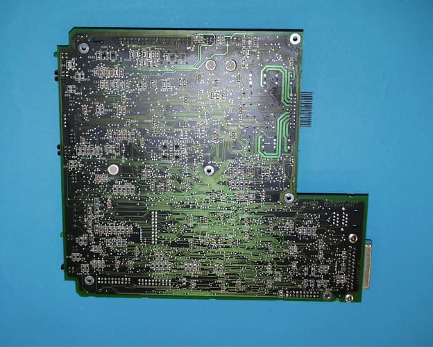
Click to zoom
Application Details
- Equipment Class
- DSS - Part 15 Spread Spectrum Transmitter
- Date of Grant
- Apr 19, 1999
- Application Purpose
- Original Equipment
- Date of Application
- Feb 15, 1999
- Equipment Note
- Tracer, Rack Mount
- Frequency Range
- 2422.00000000 - 2462.00000000
- Company
- Adtran
- Country
- United States
Documents & Files
Document Text
Text extracted from the exhibit documents filed with the FCC. Open a document above to read the original.
Users Manual
61280.003L1-1BPAGE I 6/18/98 TRACER USER’S MANUAL PAGE II61280.003L1-1B 6/18/98 RADIO FREQUENCY INTERFERENCE STATEMENT This equipment has been tested and found to comply with the limits for an intentional radiator, pursuant to Part 15, Subpart C of the FCC Rules. This equipment generates, uses, and can radiate radio frequency energy. If not installed and used in accordance with the instructions, it may cause interference to radio communications. The limits are designed to provide reasonable protection against such interference in a residential situation. However, there is no guarantee that interference will not occur in a particular installation. If this equipment does cause interference to radio or television reception, which can be determined by turning the equipment on and off, the user is encouraged to try to correct the interference by one or more of the following measures: • Reorient or relocate the receiving antenna of the affected radio or television. • Increase the separation between the equipment and the affected receiver. • Connect the equipment and the affected receiver to power outlets on separate circuits. • Consult the dealer or an experienced radio/TV technician for help. W A R N I N G Changes or modifications not expressly approved by ADTRAN could void the user’s authority to operate the equipment. SHIELDED CABLES A shielded-type power cord is required in order to meet FCC emission limits and also to prevent interference with nearby radio and television reception when using the AC voltage adapter. It is essential that only the Adtran-provided power cord be used. FCC OUTPUT POWER RESTRICTIONS The FCC does not require licensing to implement this device. However, the FCC has established restrictions regarding maximum output power and the adjustments required when employing directional gain antennae. (Refer to “Setting the Transmitter Power” in Section 2 of this manual). These restrictions are detailed in FCC Part 15.247 (b)(1), (b)(3)(i), and (3)(iii). It is the responsibility of the individuals designing and implementing the radio system to assure compliance with these and any other pertinent FCC Rules and Regulations. This device must be professionally installed. 61280.003L1-1BPAGE III 6/18/98 EXPOSURE TO RADIO FREQUENCY FIELDS This device is designed to provide a maximum power output of 100 mW. This level of RF energy in itself is below the Maximum Permissible Exposure (MPE) levels specified in FCC OET 65:97-01. The installation of high gain antenna equipment in the system configuration may create the opportunity for exposure to levels higher than recommended for the general population at a distance less than one meter from the center of the antenna. The following precautions must be taken during installation of this equipment: • The installed antenna must not be located in a manner that allows exposure of the general population to the direct beam path of the antenna at a distance less than one meter. Installation on towers, masts, or rooftops not accessible to the general population is recommended; or • Mount the antenna in a manner that prevents any personnel from entering the area within one meter from the front of the antenna • During antenna installation, be sure that power to the Tracer equipment is turned off in order to prevent any energy presence on the coaxial connector. • During installation and alignment of the antenna, do not stand in front of the antenna assembly. • During installation and alignment of the antenna, do not handle or touch the front of the antenna. These simple precautions must be taken to prevent general population and installation personnel from exposure to RF energy in excess of specified MPE levels. PAGE IV61280.003L1-1B 6/18/98 61280.003L1-1BPAGE V 6/18/98 CONTENTS INSTALLATION PAGE SECTION 1TRACER DESCRIPTION..................................................... 1 I NTRODUCTION.............................................................. 1 ISM BAND SPREAD SPECTRUM................................... 1 APPLICATIONS............................................................... 2 S PREAD SPECTRUM........................................................ 2 Direct Sequence ........................................................... 3 Coding .......................................................................... 3 CHANNEL SELECTION................................................. 3 F ORWARD ERROR CORRECTION.................................... 4 T1 OPERATION....................................................... 4 Framing ........................................................................ 4 Line Code ..................................................................... 4 DS1/DSX-1 Interface .................................................... 5 Line Buildout or LBO .................................................... 5 TRACER SYSTEM CONFIGURATION.................................. 6 Baseband Processor or BBP ........................................ 6 DS1/DSX-1 Interface .................................................... 6 VT-100 RS-232 Interface ............................................. 8 Alarm Contacts ............................................................. 8 IF Signal ....................................................................... 8 AC/DC Power ................................................................ 9 Controls and Indicators ............................................... 9 Radio Frequency Convertor or RFC ........................... 11 Antenna ...................................................................... 13 SECTION 2INSTALLATION.............................................................. 15 UNPACK, INSPECT........................................................ 15 RACK-MOUNTED RFC CONFIGURATION......................... 15 M AST-MOUNTED RFC CONFIGURATION......................... 15 I NSTALLATION.............................................................. 16 LOCATION..............................…
Text truncated - open the document above for the full version.
Attestation Statements
4317-A Park Drive NW Norcross, GA 30093 Phone: (770) 925-2444 Fax: (770) 925-7294 April 19, 1999 Federal Communications Commission Authorization & Evaluation Division 7435 Oakland Mills Road Columbia, Maryland USA, 21046 Mr. Dichoso: Subject: Part 15 Certification for Spread Spectrum Equipment FCC ID: HDCTRACERT1L7 As outlined in §0.459 fo the FCC rules, please accept this letter as Adtran’s request to withhold the sections listed below from public inspection. Transceiver Schematics Exhibit RF Block Diagram Exhibit If you have any questions, or need any additional information, feel free to contact either myself or David Dennis, EMC Team Leader. I can be reached by telephone (770) 925-2444 or by fax (770) 925-7294. Sincerely, David J. Schramm EMC Technical Supervisor Cc: Jeff Whitmire– Compliance Engineer, Adtran
Internal Photos
EXHIBIT 4 EQUIPMENT PHOTOGRAPHS Photograph 4.1: Rack Mount Transmitter Photograph 4.2: Rack Mount Transmitter Rear View Photograph 4.3: Rack Mount Transmitter (housing removed) Top View Photograph 4.4: RF Section Top View Photograph 4.5: RF Section Bottom View Photograph 4.6: RF Assembly/RF2 PCB Top View Photograph 4.7: RF Assembly/RF2 PCB Bottom View Photograph 4.8: RF Assembly TX/RX PCB Top View Photograph 4.9: RF Assembly TX/RX PCB Top View (continued) Photograph 4.10: RF Assembly TX/RX PCB Bottom View Photograph 4.11: RF Assembly TX/RX PCB Bottom View (continued) Photograph 4.12: Diplexer/Filter Top View Photograph 4.13: Diplexer Filter Bottom View Photograph 4.14: Baseband Processor Assembly Front View Photograph 4.15: Baseband Processor Back View Photograph 4.16: Baseband Processor PCB Photograph 4.17: Processor Board Top View Photograph 4.18: Processor Board Top View (continued) Photograph 4.19: Processor Board Bottom View Photograph 4.20: Processor Board Bottom View (continued) Photograph 4.21: IF Assembly Top View Photograph 4.22: IF Assembly Bottom View Photograph 4.23: Power Supply
Test Report
Intertek Testing Services FCC ID: HDCTRACERT1L7 4280TRACERT1L7 Adtran Inc. i Application for Certification Adtran Inc. Tracer Rack Mount Model: 4280TRACERT1L7 47 CFR, Part 15, Subpart C, §15.247 Spread Spectrum Transmitters FCC ID: HDCTRACERT1L7 January 27, 1999 J98030625 RPT# AD30625c.CER s:\emc\emissions\certs\1999\ad30625c.cer Intertek Testing Services FCC ID: HDCTRACERT1L7 4280TRACERT1L7 Adtran Inc. i TABLE OF CONTENTS 1.0GENERAL DESCRIPTION.......................................................................................................................1 1.1PRODUCT DESCRIPTION.............................................................................................................................1 1.2RELATED SUBMITTAL(S) GRANTS..............................................................................................................2 1.3TEST METHODOLOGY................................................................................................................................2 1.4TEST FACILITY..........................................................................................................................................2 2.0SYSTEM TEST CONFIGURATION.........................................................................................................3 2.1JUSTIFICATION..........................................................................................................................................3 2.2EUT EXERCISING SOFTWARE....................................................................................................................3 2.3SPECIAL ACCESSORIES..............................................................................................................................4 2.4EQUIPMENT MODIFICATIONS.....................................................................................................................4 2.5SUPPORT EQUIPMENT LIST AND DESCRIPTION............................................................................................5 2.6TEST CONFIGURATION BLOCK DIAGRAM...................................................................................................5 3.0TEST RESULTS.........................................................................................................................................6 3.1EMISSION BANDWIDTH..............................................................................................................................6 3.2POWER OUTPUT........................................................................................................................................7 3.2.1Specific Absorption Rate and Maximum Permissible Exposure........................................................7 3.3FIELD STRENGTH CALCULATION................................................................................................................8 3.4TRANSMITTER SPURIOUS EMISSIONS..........................................................................................................9 3.5TRANSMITTER SPURIOUS EMISSION DATA:.................................................................................................9 3.6AC POWER LINE-CONDUCTED EMISSIONS................................................................................................34 3.7POWER SPECTRAL DENSITY.....................................................................................................................42 3.8RADIATED AND LINE-CONDUCTED EMISSION CONFIGURATION PHOTOGRAPHS..........................................45 4.0MISCELLANEOUS INFORMATION.....................................................................................................49 4.1DISCUSSION OF PULSE DESENSITIZATION.................................................................................................49 4.2CALCULATION OF AVERAGE FACTOR.......................................................................................................49 4.3EMISSIONS TEST PROCEDURES.................................................................................................................50 Intertek Testing Services FCC ID: HDCTRACERT1L7 4280TRACERT1L7 Adtran Inc. ii List of Figures Figure 3.1 - 1: Emissions Bandwidth Plot...............................................................................................................6 Figure 3.5 - 1: Conducted Spurious - Frequency Plan A........................................................................................12 Figure 3.5 - 2: Conducted Spurious - Frequency Plan B........................................................................................13 Figure 3.5 - 3: Comsat RSI Grid Parabolic (P-24A36GN-U) 24.8 dBi - Peak Plot..................................................15 Figure 3.5 - 4: Comsat RSI Grid Parabolic (P-24A36GN-U) 24.8 dBi - Average Plot............................................16 Figure 3.5 - 5: Comsat RSI Grid Parabolic (P-24A36GN-U) 24.8 dBi - Restricted Band, Vertical..........................17 Figure 3.5 - 6: Comsat RSI Grid Parabolic (P-24A36GN-U) 24.8 dBi - Restricted Band, Horizontal......................18 Figure 3.5 - 7: Comsat RSI Grid Parabolic (P-24A36GN-U) 24.8 dBi - Peak Plot..................................................15 Figure 3.5 - 8: Comsat RSI Grid Parabolic (P-24A36GN-U) 24.8 dBi - Average Plot............................................16 Figure 3.5 - 9: Comsat RSI Grid Parabolic (P-24A36GN-U) 24.8 dBi - Restricted Band, Vertical..........................17 Figure 3.5 - 10: Comsat RSI Grid Parabolic (P-24A36GN-U) 24.8 dBi - Restricted Band, Horizontal....................18 Figure 3.5 - 11: Cushcraft Yagi (PC-2415N) 13.9 dBi - Peak Plot.........................................................................25 Figure 3.5 - 12: Cushcraft Yagi (PC-2415N) 13.9 dBi - Average Plot....................................................................26 Figure 3.5 - 13: Cushcraft Yagi (PC-2415N) 13.9 dBi - Restricted Band, Vertical...............…
Text truncated - open the document above for the full version.
Contact Information
Applicant
Paul Stover(Manager Compliance Engineering)
Technical Contact
Intertek Testing ServicesDavid J Schramm
[email protected]770-925-2444
4317-A Park DR NW · Norcross, Georgia · United States
Non-Technical Contact
Intertek Testing ServicesDavid J Schramm
[email protected]770-925-2444
Test Firm
Intertek Testing ServicesDavid Dennis
770-925-2444Fax: 770-925-7294
Technical Specifications
| # | Rule Parts | Frequency Range | Power Output |
|---|---|---|---|
| 1 | 15C | 2.42 GHz - 2.46 GHz | 100.00 mW |
Other Applications from Adtran
HDC-17600083
Jul 30, 2026WiFi 7 10G Router
Equipment Class
NII - Unlicensed National Information Infrastructure TX
HDC-17600087
Apr 21, 2026WiFi 7 2.5G Router
Equipment Class
NII - Unlicensed National Information Infrastructure TX
HDC-17600085
Mar 01, 2026WiFi 7 2.5G Router
Equipment Class
NII - Unlicensed National Information Infrastructure TXHDC-17600073
Jan 22, 2024WiFi 6E Mesh AP
Equipment Class
DTS - Digital Transmission System
HDC17600021F1
Jul 31, 2021WiFi 5 Gigabit Router
Equipment Class
DSS - Part 15 Spread Spectrum Transmitter