HDCTRC4205TRACER 4205
Adtran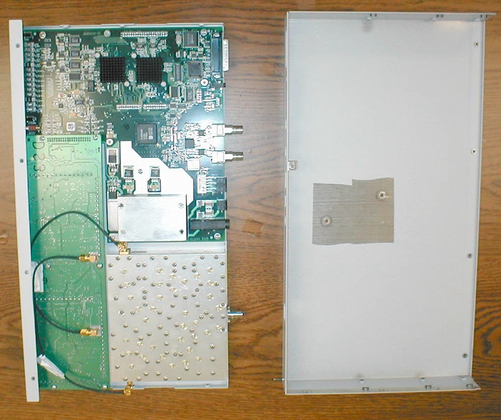
Click to zoom
Application Details
- Equipment Class
- DTS - Digital Transmission System
- Date of Grant
- Feb 10, 2003
- Application Purpose
- Original Equipment
- Date of Application
- Feb 10, 2003
- Equipment Note
- TRACER 4205
- Frequency Range
- 5747.00000000 - 5827.00000000
- Company
- Adtran
- Country
- United States
Documents & Files
Document Text
Text extracted from the exhibit documents filed with the FCC. Open a document above to read the original.
Users Manual
TRACER 4205 System Manual 12804205L1ATRACER 4205 System (Plan A) 12804205L1BTRACER 4205 System (Plan B) 612804205L1-1A August 2002 Trademarks Any brand names and product names included in this manual are trademarks, registered trademarks, or trade names of their respective holders. To the Holder of the Manual The contents of this manual are current as of the date of publication. ADTRAN reserves the right to change the contents without prior notice. In no event will ADTRAN be liable for any special, incidental, or consequential damages or for commercial losses even if ADTRAN has been advised thereof as a result of issue of this publication. 901 Explorer Boulevard P.O. Box 140000 Huntsville, AL 35814-4000 Phone: (256) 963-8000 ©2002 ADTRAN, Inc. All Rights Reserved. Printed in U.S.A. 612804205L1-1A© 2002 ADTRAN, Inc.3 About this Manual This manual provides a complete description of the TRACER 4205 system and system software. The purpose of this manual is to provide the technician, system administrator, and manager with general and specific information related to the planning, installation, operation, and maintenance of the TRACER 4205. This manual is arranged so that needed information can be quickly and easily found. The following is an overview of the contents. Section 14205 System Description Provides managers with an overview of the TRACER 4205 system. Section 2Microwave Path Engineering Basics Explains the basics of analyzing a wireless microwave link, or path. The significant parameters are defined, and several recommendations are offered. Section 3Engineering Guidelines Provides information to assist network designers with incorporating the TRACER 4205 system into their networks. Section 4Network Turnup Procedure Provides step-by-step instructions on how to install the TRACER 4205 unit, determine the parameters for the system, install the network and option modules, and power up the system. Section 5User Interface Guide Explains the terminal interface and provides a description for each of the menus available for the TRACER 4205 system. Section 6Troubleshooting Guide Provides helpful information for troubleshooting common configuration problems for the TRACER 4205 system. Revision History This is the first issue of this manual. 4© 2002 ADTRAN, Inc.612804205L1-1A Safety Instructions When using your telephone equipment, please follow these basic safety precautions to reduce the risk of fire, electrical shock, or personal injury: 1. Do not use this product near water, such as a bathtub, wash bowl, kitchen sink, laundry tub, in a wet basement, or near a swimming pool. 2. Avoid using a telephone (other than a cordless-type) during an electrical storm. There is a remote risk of shock from lightning. 3. Do not use the telephone to report a gas leak in the vicinity of the leak. 4. Use only the power cord, power supply, and/or batteries indicated in the manual. Do not dispose of batteries in a fire. They may explode. Check with local codes for special disposal instructions. Save These Important Safety Instructions Notes provide additional useful information. Cautions signify information that could prevent service interruption. Warnings provide information that could prevent damage to the equipment or endangerment to human life. 612804205L1-1A© 2002 ADTRAN, Inc.5 Federal Communications Commission Radio Frequency Interference Statement This equipment has been tested and found to comply with the limits for a Class A digital device, pursuant to Part 15 of the FCC Rules. These limits are designed to provide reasonable protection against harmful interference when the equipment is operated in a commercial environment. This equipment generates, uses, and can radiate radio frequency energy and, if not installed and used in accordance with the instruction manual, may cause harmful interference to radio frequencies. Operation of this equipment in a residential area is likely to cause harmful interference in which case the user will be required to correct the interference at his own expense. Shielded cables must be used with this unit to ensure compliance with Class A FCC limits. Changes or modifications to this unit not expressly approved by the party responsible for compliance could void the user’s authority to operate the equipment. 6© 2002 ADTRAN, Inc.612804205L1-1A Warranty and Customer Service ADTRAN will repair and return this product within five years from the date of shipment if it does not meet its published specifications or fails while in service. For detailed warranty, repair, and return information refer to the ADTRAN Equipment Warranty and Repair and Return Policy Procedure. Return Material Authorization (RMA) is required prior to returning equipment to ADTRAN. For service, RMA requests, or further information, contact one of the numbers listed at the end of this section. LIMITED PRODUCT WARRANTY ADTRAN warrants that for five years from the date of shipment to Customer, all products manufactured by ADTRAN will be free from defects in materials and workmanship. ADTRAN also warrants that products will conform to the applicable specifications and drawings for such products, as contained in the Product Manual or in ADTRAN's internal specifications and drawings for such products (which may or may not be reflected in the Product Manual). This warranty only applies if Customer gives ADTRAN written notice of defects during the warranty period. Upon such notice, ADTRAN will, at its option, either repair or replace the defective item. If ADTRAN is unable, in a reasonable time, to repair or replace any equipment to a condition as warranted, Customer is entitled to a full refund of the purchase price upon return of the equipment to ADTRAN. This warranty applies only to the original purchaser and is not transferable without ADTRAN's express written permission. This warranty becomes null and void if Customer modifies or alters the equipment in any way, other than as specifically authorized by ADTRAN. E…
Text truncated - open the document above for the full version.
Block Diagram
Modulator I Q 280 MHz IF 5827 MHz 5747MHz SAW PA 5827 MHz 5747 MHz X 4 5547 MHz 5467 MHz VCO 1386.75 MHz 1366.75 MHz 12 MHz VCO 280 MHz 280 MHz AGC 5827 MHz 5747 MHz 140 MHz IF SAW Coupler I Q 280 MHz X 4 5687 MHz 5607 MHz VCO 1421.75 MHz 1401.75 MHz TX RX AGC Control Attenuator Demodulator 12 MHz 12 MHz TX RX
Block Diagram
SAW AGC PA VCO 12 MHz Modulator VCO 280 TX TX I Q SAW AGC Coupler VCO Control Demodulator RX Attenuator RX I Q X 4 X 4
Cover Letter(s)
American Telecommunications Certification Body Inc. 6731 Whittier Ave, McLean, VA 22101 January 27, 2003 RE: FCC ID: HDCTRC4205 Attention: Gregory M. Snyder / Brian J. Dettling I have a few comments on this Application. 1. Please note that the 731 states DSS (Frequency Hopping) as the type device. This is a DTS (Digital transmission System). Please correct the 731 to give the proper EUT type. 2. Please note that for information to be provided with a Part 15 device 2.1033(a)(5) states, “A block diagram showing the frequency of all oscillators in the device. The signal path and frequency shall be indicated at each block. The tuning range(s) and intermediate frequency(ies) shall be indicated at each block. A schematic diagram is also required for intentional radiators.” Please provide a Block diagram that fits the requirements of 2.1033. 3. In section 3.1 of the report you state that a diode detector and oscilloscope was used to measure conducted power because the analyzer used for testing did not have the correct bandwidth. You then state that a power meter was used to measure the output of the signal generator. Why wasn’t the power meter with peak head used to directly measure the output of the device itself? 4. You incorrectly list 110.94MHz, 156.84MHz and 257.46MHz in an average table (Table 7). Frequencies below 1000MHz and above 30MHz are QP. Please retest these frequencies to QP and not Average. Alternately, if it is the case, re-label these frequencies as QP. 5. Please note that when measuring between 30MHz to 1000MHz for radiated spurious emissions the video BW of an analyzer is to be equal to or greater than the RBW. This is because when the video bandwidth is less than the resolution bandwidth the analyzer begins to average. Typically averaging does not really begin until the VBW is 1/10 the RBW, but none the less when the VBW is less than the RBW the analyzer is not set properly. Section 3.5 of your report states a Video BW of >30kHz. Please verify that the Video BW was equal to or greater than the RBW Dennis Ward mailto:[email protected] The items indicated above must be submitted before processing can continue on the above referenced application. Failure to provide the requested information may result in application termination. Correspondence should be considered part of the permanent submission and may be viewed from the Internet after a Grant of Equipment Authorization is issued. Please do not respond to this correspondence using the email reply button. In order for your response to be processed expeditiously, you must submit your documents through the AmericanTCB.com website. Also, please note that partial responses increase processing time and should not be submitted. Any questions about the content of this correspondence should be directed to the sender.
Cover Letter(s)
Response to ATCB Comments FCC ID: HDCTRC4205 1 Washington Laboratories, Ltd. 7560 LINDBERGH DRIVE GAITHERSBURG, MD 20879 (301) 417 – 0220 FAX # (301) 417 - 9069 January 31, 2003 Mr. Dennis Ward American Telecommunications Certification Body Inc. 6731 Whittier Ave McLean, VA 22101 RE: Comments of January 27, 2003 APPLICATION: HDCTRC4205 Adtran, Inc. Dear Mr. Ward: Below are the comments that you have provided regarding the application for certification referenced above. Our responses to those comments are in bold italic. Many responses refer you to additional exhibit(s) which has been uploaded to the application folder at the ATCB website. Thank you for your attention. Please feel free to contact us for any additional information that you may require. Regards, Gregory M. Snyder Chief EMC Engineer, Wireless/Telco Services Manager Brian J. Dettling Documentation Specialist WLL Project: 7368 January 27, 2003 RE: Adtran, Inc. FCC ID: HDCTRC4205 1) Please note that the 731 states DSS (Frequency Hopping) as the type device. This is a DTS (Digital transmission System). Please correct the 731 to give the proper EUT type. R. The 731 Form has been revised. Please see exhibit “4205 Form 731 1.30.03.pdf.” Response to ATCB Comments FCC ID: HDCTRC4205 2 2) Please note that for information to be provided with a Part 15 device 2.1033(a)(5) states, “A block diagram showing the frequency of all oscillators in the device. The signal path and frequency shall be indicated at each block. The tuning range(s) and intermediate frequency(ies) shall be indicated at each block. A schematic diagram is also required for intentional radiators.” Please provide a Block diagram that fits the requirements of 2.1033. R. Please see exhibit “4205 Block Diagram.pdf.” 3) In section 3.1 of the report you state that a diode detector and oscilloscope was used to measure conducted power because the analyzer used for testing did not have the correct bandwidth. You then state that a power meter was used to measure the output of the signal generator. Why wasn’t the power meter with peak head used to directly measure the output of the device itself? R. We do not have a peak power meter for performing this measurement directly. The power meter was only used to measure the CW signal provided by the signal generator. This substitution method has been used previously. 4) You incorrectly list 110.94MHz, 156.84MHz and 257.46MHz in an average table (Table 7). Frequencies below 1000MHz and above 30MHz are QP. Please retest these frequencies to QP and not Average. Alternately, if it is the case, re-label these frequencies as QP. R. Measurements made below 1GHz were done as QP. The “Notes” column on the right side of the data sheet should indicate this method of measurement. The QP designation in the “Notes” column was inadvertently left out of Table 7. The test report has been revised. Please see exhibit “4205 Test Report Rev 1.pdf.” 5) Please note that when measuring between 30MHz to 1000MHz for radiated spurious emissions the video BW of an analyzer is to be equal to or greater than the RBW. This is because when the video bandwidth is less than the resolution bandwidth the analyzer begins to average. Typically averaging does not really begin until the VBW is 1/10 the RBW, but none the less when the VBW is less than the RBW the analyzer is not set properly. Section 3.5 of your report states a Video BW of >30kHz. Please verify that the Video BW was equal to or greater than the RBW. R. The Video Bandwidth setting for the QP measurements was set to 1MHz while the QP Adapter sets the measurement bandwidth to 120kHz. The test report has been revised.
External Photos
External Photos Front Rear Rear Panel Right Side Left Side Bottom Top Cover Removed
ID Label/Location Info
2.125” +/- .020” 1.00” +/- .020” .100” RAD. DATEREV ECO# COMMENT 11/25/02 @AN/A ORIGINAL REV PRODUCT DRAWN BYENGINEERAPPROVED BY A. BREMERM. GANN TITLE SCALEDWG. NO. TRACER 4106,4XT1 32897042 LABEL, FCC 1.00” 1:1 901 EXPLORER BVD. P.O. BOX 140000 HUNTSVILLE, AL 35814-4000 NOTES: 1. PRINT PER ARTWORK SUPPLIED. 2. MATERIAL: .002 WHITE MYLAR SUBSTRATE BLACK LETTERING, .001 CLEAR MYLAR OVERLAY LAMINATED, FLEXCON L-344 OR UL APPROVED EQUAL PRESSURE SENSITIVE ADHESIVE BACKSIDE. 3. FONT: HELVETICA & ERAS DEMI, NO FONT SUBSTITUTIONS PERMITTED. 4. FILM: EMULSION SIDE UP. FCC ID: HDCTRC4205 TRACER 4205 This equipment complies with part 15 of FCC rules.Operation is subject to the following two conditions: (1) This device may not cause harmful interference, and (2) This device must accept any interference received, including interference that may cause undesired operation. FCC Label Location
Internal Photos
Overview – Cover Removed Baseband Top Upper Left Baseband Top Middle Left Baseband Top Lower Left Baseband Top Right Side Baseband Bottom Upper Right Baseband Bottom Center Right Baseband Bottom Lower Right
Internal Photos
RFC Board Top Left RFC Board Top Center RFC Board Top Right RFC Board Bottom Overview RFC Board Bottom Left Side, Large Shield Removed RFC Board Bottom Left Detail, Small Shield Removed RFC Board Bottom Center RFC Board Bottom Right, Large Shield Removed RFC Board Bottom Right Detail, Small Shield Removed Signal Filter Connection Details Signal Filter Cover Open
RF Exposure Info
Maximum Permissible Exposure Test Report for Adtran, Inc. 901 Explorer Boulevard Huntsville, AL 35806 FCC ID: HDCTRC4205 January 24, 2003 WLL PROJECT #: 7368RFFCC This report may not be reproduced, except in full, without the prior written consent of Washington Laboratories, Ltd. Adtran, Inc. FCC ID: HDCTRC4205 WLL Project #: 7368RFFCC 1 Maximum Permissible Exposure Test Report for FCC ID: HDCTRC4205 1.0 Introduction This report has been prepared on behalf of Adtran, Inc. to show compliance with the RF exposure requirements as defined in FCC Part 1.1307(b)(1) for the Adtran Tracer 4205 Device. 3.8 Radio Frequency Radiation Exposure In accordance with Section 1.1310 of the FCC rules, the Maximum Permissible Exposure (MPE) limit for this frequency range is 1mW/cm 2 for General Population/Uncontrolled Access. The EUT is designed for telecommunications transmissions and may use high gain antennas (up to 32.6 dBi) and the transmitter section is designed for mounting on an antenna mast. Only professional installers install this device and is limited to installations such as towers and rooftops. Warnings are in the installation manual which limit the exposure to the direct beam during installation and maintenance. These warnings to the installers insure that the general public is not exposed to RF energy. The TRACER 4205 is designed for a transmit power of 20 dBm (100mW). Assuming the highest allowable gain antenna is used (32.6 dBi) the following power density is calculated. S = (PG)/(4πR 2 ) Where, S = Power Density P = Output Power at the Antenna Terminals G = Gain of Transmit Antenna (linear gain) R = Distance from Transmitting Antenna For this device, the calculation is as follows: S = FCC Limit = 1mW/cm 2 P = Output Power = 98.2mW (measured) G = Worst Case Gain = 32.6 dBi (1820 linear gain) R = Based on 4.6 meters (15 feet) specified in User’s Manual S = {(98.2mW)(1820}/{(12.56)(460cm 2 )} = 0.067mW/cm 2 Adtran, Inc. FCC ID: HDCTRC4205 WLL Project #: 7368RFFCC 2 This power density is the worst case for maximum beam exposure. This level is below the limit of 1mW/cm 2 MPE for general population/uncontrolled access. This unit is only installed by professionals and is limited in practice to installations on rooftops or towers. Warnings are provided in the installation manual to limit exposure to the direct beam during the installation and maintenance phase. These warnings ensure that the device is installed properly and does not expose the general public to RF energy hazards.
Test Report
Document 7368-01, Rev. 1 FCC Certification Test Report Washington Laboratories, Ltd January 2003 FCC Certification Test Report for ADTRAN, Inc. Tracer 4205 FCC ID: HDCTRC4205 January 30, 2003 Prepared for: ADTRAN, Inc. 901 Explorer Blvd Huntsville, AL 35806 Prepared By: Washington Laboratories, Ltd. 7560 Lindbergh Drive Gaithersburg, Maryland 20879 FCC Certification Test Report Document 7368-01, Rev. 1 FCC Certification Test Report Washington Laboratories, Ltd January 2003 FCC Certification Test Report for the ADTRAN, Inc. TRACER 4205 WLL JOB# 7368 Prepared by: Brian J. Dettling Documentation Specialist Reviewed by: Gregory M. Snyder Wireless/Telco Services Manager & Chief EMC Engineer Document 7368-01, Rev. 1 FCC ID: HDCTRC4203 FCC Certification Test Report Washington Laboratories, Ltd January 2003 ii Abstract This report has been prepared on behalf of ADTRAN, Inc. to support the attached Application for Equipment Authorization. The test report and application are submitted for a Digitally Modulated Transmitter under Part 15.247 of the FCC Rules and Regulations. This Federal Communication Commission (FCC) Certification Test Report documents the test configuration and test results for an ADTRAN, Inc. TRACER 4205 Transceiver. Testing was performed on an Open Area Test Site (OATS) of Washington Laboratories, Ltd, 7560 Lindbergh Drive, Gaithersburg, MD 20879. Site description and site attenuation data have been placed on file with the FCC's Sampling and Measurements Branch at the FCC laboratory in Columbia, MD. Washington Laboratories, Ltd. has been accepted by the FCC and approved by NIST NVLAP (NVLAP Lab Code: 200066-0) as an independent FCC test laboratory. The ADTRAN, Inc. TRACER 4205 Transceiver complies with the requirements for a Digitally Modulated Transmitter device under Part 15.247 of the FCC Rules and Regulations. Document 7368-01, Rev. 1 FCC ID: HDCTRC4203 FCC Certification Test Report Washington Laboratories, Ltd January 2003 iii Table of Contents Abstract......................................................................................................ii 1 Introduction...............................................................................................................1 1.1 Compliance Statement............................................................................................1 1.2 Test Scope............................................................................................................1 1.3 Contract Information..............................................................................................1 1.4 Test Dates.............................................................................................................1 1.5 Test and Support Personnel....................................................................................1 1.6 Abbreviations.........................................................................................................2 2 Equipment Under Test................................................................................................3 2.1 EUT Identification & Description............................................................................3 2.2 Test Configuration..................................................................................................3 2.3 Testing Algorithm...................................................................................................4 2.4 Test Location.........................................................................................................4 2.5 Measurements........................................................................................................4 2.5.1 References.....................................................................................................4 2.6 Measurement Uncertainty.......................................................................................4 3 Test Results...............................................................................................................5 3.1 Peak Power Output...............................................................................................5 3.2 Power Spectral Density..........................................................................................5 3.3 Occupied Bandwidth..............................................................................................7 3.4 Spurious Emissions at Antenna Terminals (FCC Part §15.247(b))...........................9 3.5 Radiated Spurious Emissions: (FCC Part §15.247(c))...........................................18 3.5.1 Test Procedure..........................................................................................18 3.6 AC Powerline Conducted Emissions: (FCC Part §15.207)...................................23 4 Test Equipment........................................................................................................25 List of Tables Table 1. Assembly Information.............................................................................................3 Table 2. RF Output Power Conducted.................................................................................5 Table 3. Power Spectral Density..........................................................................................7 Table 4. Occupied Bandwidth Results..................................................................................7 Table 5: Conducted Spurious Emissions Limits......................................................................9 Table 6: Radiated Emission Test Data-Dish Antenna—Channel A.......................................19 Table 7: Radiated Emission Test Data-Dish Antenna—Channel B.......................................21 Table 8: Conducted Emissions Test Data Sheet...............................................................24 Table 9: Test Equipment List..............................................................................................25 Document 7368-01, Rev. 1 …
Text truncated - open the document above for the full version.
Test Setup Photos
Emissions Test Setup
Contact Information
Applicant
Paul Stover(Manager Compliance Engineering)
Test Firm
Washington Laboratories, Ltd.Michael Violette
Technical Specifications
| # | Rule Parts | Frequency Range | Power Output |
|---|---|---|---|
| 1 | 15C | 5.75 GHz - 5.83 GHz | 98.00 mW |
Other Applications from Adtran
HDC-17600083
Jul 30, 2026WiFi 7 10G Router
Equipment Class
NII - Unlicensed National Information Infrastructure TX
HDC-17600087
Apr 21, 2026WiFi 7 2.5G Router
Equipment Class
NII - Unlicensed National Information Infrastructure TX
HDC-17600085
Mar 01, 2026WiFi 7 2.5G Router
Equipment Class
NII - Unlicensed National Information Infrastructure TXHDC-17600073
Jan 22, 2024WiFi 6E Mesh AP
Equipment Class
DTS - Digital Transmission System
HDC17600021F1
Jul 31, 2021WiFi 5 Gigabit Router
Equipment Class
DSS - Part 15 Spread Spectrum Transmitter