HDCTRC582TR1Point to Point Spread Spectrum System
Adtran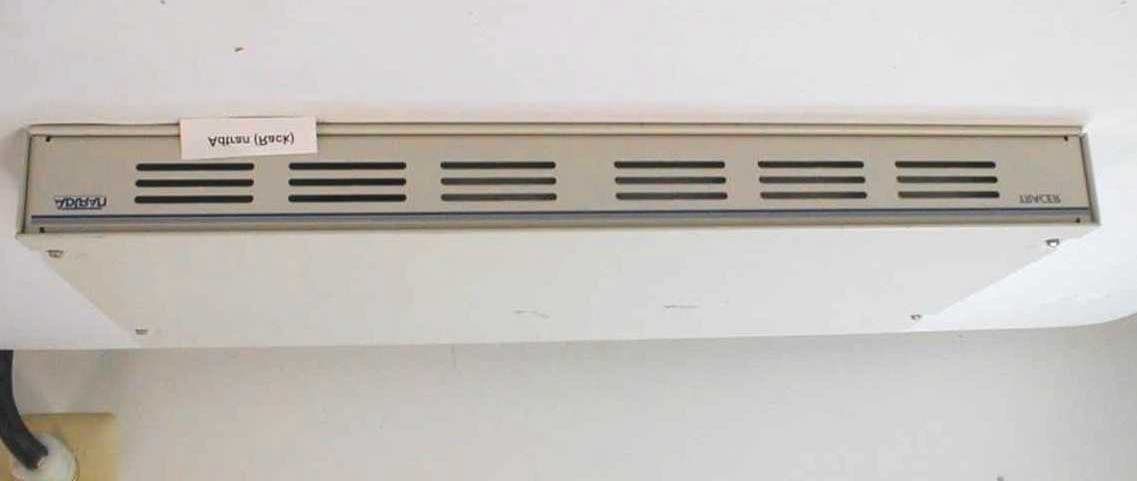
Click to zoom
Application Details
- Equipment Class
- DSS - Part 15 Spread Spectrum Transmitter
- Date of Grant
- Aug 27, 2000
- Application Purpose
- Original Equipment
- Date of Application
- Aug 27, 2000
- Equipment Note
- Point to Point Spread Spectrum System
- Frequency Range
- 5725.00000000 - 5850.00000000
- Company
- Adtran
- Country
- United States
Documents & Files
Document Text
Text extracted from the exhibit documents filed with the FCC. Open a document above to read the original.
Users Manual
TRACER 2xT1 User’s Manual61280003L2-1B Preliminary TRACER ® 2xT1 User’s Manual 61280003L2-1BTRACER 2xT1 User’s Manual Preliminary This equipment has been tested and found to comply with the limits for an intentional radiator, pursuant to Part 15, Subpart C of the FCC Rules. This equipment generates, uses, and can radiate radio frequency energy. If not installed and used in accordance with the instructions, it may cause interference to radio communications. The limits are designed to provide reasonable protection against such interference in a residential situation. However, there is no guarantee that interference will not occur in a particular installation. If this equipment does cause interference to radio or television reception, which can be determined by turning the equipment on and off, the user is encouraged to try to correct the interference by one or more of the following measures: •Reorient or relocate the receiving antenna of the affected radio or television. •Increase the separation between the equipment and the affected receiver. •Connect the equipment and the affected receiver to power outlets on separate circuits. •Consult the dealer or an experienced radio/TV technician for help. W A R N I N G Changes or modifications not expressly approved by ADTRAN could void the user’s authority to operate the equipment. Shielded Cables A shielded-type power cord is required in order to meet FCC emission limits and also to prevent interference with nearby radio and television reception when using the AC voltage adapter. It is essential that only the Adtran-provided power cord be used. FCC Output Power Restrictions The FCC does not require licensing to implement this device. However, the FCC has established restrictions regarding maximum output power and the adjustments required when employing directional gain antennas. (Refer to “Setting the Transmitter Power” in Section 2 of this manual). These restrictions are detailed in FCC Part 15.247 (b)(1), (b)(3)(i), and (3)(iii). It is the responsibility of the individuals designing and implementing the radio system to assure compliance with these and any other pertinent FCC Rules and Regulations. This device must be professionally installed. Exposure to Radio Frequency Fields The TRACER is designed in three versions with the following power options: 2.4 GHz @ 100 mw 2.4 GHz @ 1 w 5.8 GHz @100 mw These levels of RF energy in are below the Maximum Permissible Exposure (MPE) levels specified in FCC OET 65:97-01. The installation of high gain antenna equipment in the system configuration may create the opportunity for exposure to levels higher than recommended for occupation/controlled personnel a distance less than 8 feet (2.5meters) from the center of the antenna. The following precautions must be taken during installation of this equipment: RADIO FREQUENCY INTERFACE STATEMENT TRACER 2xT1 User’s Manuali Preliminary TRACER 2xT1 User’s Manual 61280003L2-1B Radio Frequency Interference Statement ii Preliminary •The installed antenna must not be located in a manner that allows exposure of the general population to the direct beam path of the antenna at a distance less than 8 feet (2.5 meters). Installation on towers, masts, or rooftops not accessible to the general population is recommended; or • Mount the antenna in a manner that prevents any personnel from entering the area within 8 feet (2.5 meters) from the front of the antenna. •It is recommended that the installer place radio frequency hazard warnings signs on the barrier that prevents access to the antenna. •Prior to installing the antenna to the RFC output, make sure the power is adjusted to the settings specified in section 2 of this manual. •During antenna installation, be sure that power to the TRACER equipment is turned off in order to prevent any energy presence on the coaxial connector. •During installation and alignment of the antenna, do not stand in front of the antenna assembly. •During installation and alignment of the antenna, do not handle or touch the front of the antenna. These simple precautions must be taken to prevent occupational and installation personnel from exposure to RF energy in excess of specified MPE levels. TRACER 2xT1 User’s Manual 61280003L2-1B Table of Contents iii Preliminary Page Section 1 TRACER Description Introduction .................................................................................................................................1 ISM Band Spread Spectrum........................................................................................................1 NEBS...........................................................................................................................................1 Applications.................................................................................................................................2 Spread Spectrum..........................................................................................................................2 Direct Sequence.........................................................................................................2 Coding.......................................................................................................................2 Channel Selection........................................................................................................................3 Forward Error Correction............................................................................................................3 T1 Operation..............................................................................................................3 Framing.......................................................................................................3 Line Code ...................................................................................................4 DS1/DSX-1 Interface .................................................................................4 Line Buil…
Text truncated - open the document above for the full version.
Block Diagram
TRACER 2xT1 User’s Manual 61280003L2-1B Section 1 TRACER Description 9Preliminary Three SMA connectors, located on the RFC module, provide RF and IF connection points. A test point is provided for monitoring the received signal strength indicator (RSSI). The voltage (relative to the GND test point) present on this test point represents the level of the received signal. This signal is used to align the antenna when installing the system and to verify the link is performing as designed. Another test point is provided to monitor the transmitter output power during system configuration. The only connections that must be made in the field are a coax connection between the baseband processor and the RFC and a coax connection between the RFC and the antenna. These connections require male, type N coax connectors. The IF connector provides the connection between the baseband processor and the rackmounted or mastmounted RFC. (An 8-inch IF cable [ADTRAN part # 3125RF027@A] is provided for rackmount systems). The TO ANTENNA connection provides the connection between the RFC and the antenna. A block diagram of the RFC functions is show in Figure 1-9. The RFC module is enclosed in either a 19-inch EIA rackmount housing, or a weather-tight enclosure suitable for mastmounting near the antenna for enhanced system performance. The RFC mastmount and rackmount housings are illustrated in Figures 1-10 and 1-11. Figure 1-8. RFC Module R X T X I F R S S I G N D T X -P W R RFC Function Block Diagram SAW 333 2321 2281 AGC Splitter Splitter AGC PA LPF RF2 IF 20185344 or 20585424 5607 or 5687 Tx Rx
External Photos
Front View Rear View
ID Label/Location Info
FCC ID: HDCTRC582TR1 TRACER This equipment complies with part 15 of FCC rules.Operation is subject to the following two conditions: (1) This device may not cause harmful interference, and (2) This device must accept any interference received, including interference that may cause undesired operation. 2.125” +/- .030” 1.00” +/- .030” .100” RAD. DATEREV ECO# COMMENT 8/15/00 @AN/A ORIGINAL REV PRODUCT DRAWN BYENGINEERAPPROVED BY A. BREMERT. HARRIS TITLE SCALEDWG. NO. 5.8GHz TRACER, R.M. 32895249 LABEL, FCC 1.00” 1:1 901 EXPLORER BVD. P.O. BOX 140000 HUNTSVILLE, AL 35814-4000 NOTES: 1. PRINT PER ARTWORK SUPPLIED. 2. MATERIAL: .002 WHITE MYLAR SUBSTRATE BLACK LETTERING, .001 CLEAR MYLAR OVERLAY LAMINATED, FLEXCON V.23 PRESSURE SENSITIVE ADHESIVE BACKSIDE. 3. FONT: HELVETICA BOLD, NO FONT SUBSTITUTIONS PERMITTED. 4. FILM: EMULSION SIDE UP.
Internal Photos
Rack Mount, Cover Off Rack Mount, Cover Off 2 Rack Mount, Cover Off 3 Transmitter PCB, Top Transmitter PCB, Bottom Receiver PCB, Top Receiver PCB, Bottom RFC PCB, Top RFC PCB, Bottom RF Top View RF Top Cover RF Housing, Top View RF Housing, Front View RF Housing, Bottom View RF Bottom View
Operational Description
TRACER Operational Description APPLICATIONS Any application that would typically use metallic T1 as a transport can use the TRACER instead. Figure 1-1 illustrates a typical application. The TRACER can be used in any application requiring that data be shared at a high rate of speed. In addition to telephony applications, TRACER can be used in data communications such as inter- networking, video conferencing, and telemetry. SPREAD SPECTRUM Spread spectrum is a form of communication in which the bandwidth of a message signal is intentionally increased or “spread.” The FCC rules allow two methods of spreading – frequency hopping and direct sequence. TRACER employs direct sequence spread spectrum. Direct Sequence A direct sequence transmitter spreads the signal by mixing the data with the output of a pseudorandom number generator which changes state at a rate higher than the data rate. This rate is called the “chipping” rate. The TRACER chipping rate is twelve times the data rate. Coding Many different pseudorandom sequences exist. The sequences are called pseudorandom because, although they appear noise-like, they are determinant and repeat after a specific number of chips. The longer a code is, the better correlation characteristics it possesses. These traits allow multiple spread Figure 1-1. Typical Application Terminal VT-100 Switch Cell Radio RS-232 Cellular/PCS Site AntennaAntenna IF Cable RF Cable Mast Unit Mast and Rack mount RFCs may be mixed to accommodate individual system requirements. TRACER Baseband Processor 2xT1, Rack-mounted RFC TRACER Baseband Processor T1 T1 T1 T1 MSC T 1 B D A T A A I S B D A T A A I S T 1 P O W T RA N SC EI T R A C E R 2xT1, Mast-mounted RFC T R A C E R T 1 B P D A T A A I S B D A T A A I S T 1 P O W T R A N S C E I T R A C E R Rack-mount RFC RF Cable spectrum systems to operate in the presence of one another with minimal interference if they are operating with different sequences. The TRACER allows the selection of one of ten different 120-bit long sequences. CHANNEL SELECTION The FCC has allocated 83.5 MHz of spectrum in the 2.4 GHz band and 125 MHz in the 5.8 GHz band in which TRACER operates. A TRACER system fully uses the available bandwidth – transmitting in one half and receiving in the other. Figure 1-2 illustrates the bandwidth division. The transmitter at one end (TxA) of a link will transmit in the lower half of the spectrum. Consequently the receiver at the other end will receive in the lower half of the band and transmit in the upper half. Thus, a system will operate in one of two frequency plans – transmit in the upper and receive in the lower or vice versa. These two plans are called Plan A and Plan B. One end of a path will be on Plan A and the other will be on Plan B. Shipment of a link will consist of an A and a B unless otherwise specified. FORWARD ERROR CORRECTION With the addition of overhead data, error detection and correction capability can be added to a data stream. Error correction can be accomplished by allowing the receiver to request the re-transmission of an errored block once detected. The TRACER, on the other hand, implements forward error correction (FEC) which adds enough overhead data for the receiver to detect and correct errors in the data stream. This capability comes at the cost of bandwidth. The addition of FEC decreases the required signal-to- noise (S/N) ratio by approximately 5.5 dB to achieve a given bit error rate (BER). T1 Operation Framing The data in a T1 stream is delimited by framing bits. The pattern of the framing bits follows one of two formats -- extended superframe ( ESF) or superframe (SF). The T1 interface must be prepared for the format that will be used. Figure 1-2. Bandwidth Division 2400 MHz 2441 MHz 2483.5 MHz 5725 MHz 5787 MHz or 5850 MHz Line Code A mark in the data stream is coded as a pulse on the T1 line. A space is coded as “no activity” on the T1 line. As a form of error detection, subsequent marks in the data stream are coded as pulses of alternating polarity, either positive going or negative going. This type of line coding is called alternate mark inversion (AMI). For the T1 receiver to operate correctly, a minimum number of “1s” must exist on the T1 facility. If the data cannot be guaranteed to meet this requirement, then another line coding format is used. In the bipolar 8 zero substitution (B8ZS) scheme, a string of eight “0s” is replaced by a special sequence of eight bits that contains a bipolar violation. The receiver, upon recognizing this sequence, reinserts the eight “0s” and the data is recovered intact. DS1/DSX-1 Interface When connecting the interface to the public switched network, an ADTRAN-provided cross-over cable (part number 3125M011@A) is required to meet FCC part 68 and IC CS03 requirements. This cable is required to cross-over the Tx and Rx pairs to meet the connecting arrangement of a network interface device. This cable is included with the BBP and is labelled “T1 Crossover.” Line Buildout or LBO The DS1/DSX-1 interface provides two different types of line buildouts (LBOs), respectively. When set for DS1, LBOs for 0 dB, -7.5 dB, -15 dB, and -22 dB are available. The DS1 interface can operate on line lengths up to 6,000 feet. When set for DSX-1 interface, LBOs for 0-133 feet, 266-399 feet, 399-533 feet, and 533-655 feet are available. TRACER SYSTEM CONFIGURATION A TRACER system is composed of three major subsystems -- a baseband processor, a radio frequency convertor, and an antenna. The following section describes the system components. Baseband Processor or BBP The BBP (ADTRAN part number 1280003L2) is a 1-U, 19-inch rackmountable unit that provides the system electrical interfaces, user controls and indicators, and performs the spread spectrum processing for the system. The rear panel provides all of the electrical interface points -- DS1/DSX-1 interface, DS1/DSX-1 monitor, VT-100 terminal, alarm contacts, IF signal, DC power (from facility), and power (from A…
Text truncated - open the document above for the full version.
RF Exposure Info
Maximum Permissible Exposure Test Report for Adtran, Inc. 901 Explorer Boulevard Huntsville, AL 35806 FCC ID: HDCTRC582TR1 Rack Mount August 8, 2000 WLL PROJECT #: 5896X This report may not be reproduced, except in full, without the prior written consent of Washington Laboratories, Ltd. Adtran, Inc. FCC ID: HDCTRC582TR1 WLL Project #: 5896X 1 Maximum Permissible Exposure Test Report for FCC ID: HDCTRC582TR1 1.0 Introduction This report has been prepared on behalf of Adtran, Inc. to show compliance with the RF exposure requirements of FCC Part 15.247(b)(4) as defined in FCC Part 1.1307(b)(1) for the Adtran TRACER 2xT1 DSSS Rack Mount unit. 2.0 Radio Frequency Radiation Exposure In accordance with Section 1.1310 of the FCC rules, the Maximum Permissible Exposure (MPE) limit for this frequency range is 1mW/cm 2 for General Population/Uncontrolled Access. The EUT is designed for telecommunications transmissions and may use relatively large antennas (12’ dish) and the transmitter section is designed for mounting on an antenna mast. Only professional installers install this device and is limited to installations such as towers and rooftops. Warnings are in the installation manual which limit the exposure to the direct beam during installation and maintenance. These warnings to the installers insure that the general public is not exposed to RF energy. The TRACER is designed for a transmit power of 20dBm (100mW). Assuming the highest gain antenna is used (44.2dBi) the following power density is calculated. S = (PG)/(4πR 2 ) Where, S = Power Density P = Output Power at the Antenna Terminals G = Gain of Transmit Antenna (linear gain) R = Distance from Transmitting Antenna For this device, the calculation is as follows: S = FCC Limit = 1mW/cm 2 P = Output Power = 100mW G = Worst Case Gain = 44.2 dBi (26,302) R = Based on 4.6 meters (15 feet) S = {(100mW)(26302)}/{(12.56)(460cm) 2 } = 0.989mW/cm 2 This power density is the worst case for maximum beam exposure. This level is below the limit of 1mW/cm 2 MPE for general population/uncontrolled access. This unit is only installed by professionals and is limited in practice to installations on rooftops or towers. Warnings are provided in the installation manual to limit exposure to the direct beam during the installation and maintenance phase. These warnings ensure that the device is installed properly and does not expose the general public to RF energy hazards.
Test Report
FCC CERTIFICATION TEST REPORT for Adtran, Inc. 901 Explorer Boulevard Huntsville, AL 35806 FCC ID: HDCTRC582TR1 Rack Mount August 8, 2000 WLL PROJECT #: 5896X This report may not be reproduced, except in full, without the prior written consent of Washington Laboratories, Ltd. Adtran, Inc. FCC ID: HDCTRC582TM1 WLL Project #: 5775X i TABLE OF CONTENTS Statement of Qualifications 1.0 INTRODUCTION...........................................................................................................................................................1 1.1 SUMMARY......................................................................................................................................................................1 2.0 DESCRIPTION OF EQUIPMENT UNDER TEST (EUT).................................................................1 3.0 TEST CONFIGURATION............................................................................................................................................2 3.1 TESTING ALGORITHM.................................................................................................................................................2 3.2 CONDUCTED EMISSIONS TESTING...........................................................................................................................3 3.3 TRANSMITTER SPURIOUS EMISSIONS TESTING......................................................................................................5 3.3.1 Radiated Emissions Testing..............................................................................................................................5 3.3.2 Radiated Data Reduction and Reporting........................................................................................................5 3.4 CONDUCTED SPURIOUS EMISSIONS TESTING......................................................................................................10 3.5 CARRIER BANDWIDTH TESTING..............................................................................................................................10 3.6 POWER OUTPUT TESTING.........................................................................................................................................10 3.7 POWER SPECTRAL DENSITY....................................................................................................................................10 Tables Table 1. Conducted Emissions Results Table 2. Radiated Emissions Results Table 3. System Under Test Table 4. Interface Cables Used Table 5. Measurement Equipment Used Exhibits Exhibit 1. Spurious Emissions at the Antenna Terminals Exhibit 2. 6dB Bandwidth Plots Exhibit 3. Power Spectral Density Plots Appendices Appendix A. Statement of Measurement Uncertainty Adtran, Inc. FCC ID: HDCTRC582TM1 WLL Project #: 5775X ii STATEMENT OF QUALIFICATIONS for Steven Koster Washington Laboratories, Ltd. I am a NARTE-Accredited EMC Test Laboratory Engineer with over nineteen years of electronics experience, the last ten years being directly involved in EMI testing. I am qualified to perform EMC testing to the methods described in this test report. The measurements taken within this report are accurate within my ability to perform the tests and within the tolerance of the measuring instrumentation. By: _______________________ Steven Koster Compliance Engineer Date: January 1, 2000 Adtran, Inc. FCC ID: HDCTRC582TM1 WLL Project #: 5775X 1 FCC CERTIFICATION TEST REPORT for FCC ID: HDCTRC582TR1 1.0 Introduction This report has been prepared on behalf of Adtran, Inc. to support the attached Application for Equipment Authorization. The test and application are submitted for an Intentional Radiator under Part 15.247 of the FCC Rules and Regulations. The Equipment Under Test was the Adtran Inc. TRACER 2xT1 Rackmount, 5.8 GHz Direct Sequence Spread Spectrum transmitter. All measurements herein were performed according to the 1992 version of ANSI C63.4. The measurement equipment conforms to ANSI C63.2 Specifications for Electromagnetic Noise and field Strength Instrumentation. Calibration checks are made periodically to verify proper performance of the measuring instrumentation. All measurements are performed at Washington Laboratories, Ltd. test center in Gaithersburg, MD. Site description and site attenuation data have been placed on file with the FCC's Sampling and Measurements Branch at the FCC laboratory in Columbia, MD. Washington Laboratories, Ltd. has been accepted by the FCC and approved by NIST NVLAP (NVLAP Lab Code: 200066-0) as an independent FCC test laboratory. All results reported herein relate only to the equipment tested. The measurement uncertainty of the data contained herein is ±2.3 dB. Refer to Appendix A for Statement of Measurement Uncertainty. This report shall not be used to claim product endorsement by NVLAP or any agency of the US Government. 1.1 Summary The Adtran, Inc. TRACER 2xT1 (Rack Mount) DSSS complies with the limits for an Intentional Radiator under Part 15.247 of the FCC Rules and Regulations. 2.0 Description of Equipment Under Test (EUT) The Adtran, Inc. TRACER 2xT1 (Rack Mount) DSSS (EUT) is a 5.8 GHz DSSS transmitter that provides dual T1 transport by microwave link. Each end of the TRACER link is composed of two units; the baseband processor (BBP) and the radio frequency converter (RFC). Both the RFC and BBP are housed in a 1U (1.75”), 19” rack mountable package. Two configurations of the TRACER 2xT1 RFC are available; the rack mountable unit as described in this report, and a Mast Mount unit (separate certification, FCC ID: HDCTRC582TM1). The two RFC configurations are identical in circuitry and operation. The only difference between the units is the external housing. This report concerns the testing and results of the rack mountable configuration. The 5.8 GHz TRACER operates on Plan A, Tx = 5747 MHz, Rx = 5827 MHz or Plan B, Tx = 5827 MHz, Rx = 5747 MHz. Two DS1/DSX1 (T1) interfaces are provided…
Text truncated - open the document above for the full version.
Test Setup Photos
Conducted Emissions Test Setup Radiated Emissions Flat Panel Antenna Radiated Emissions Test Setup Parabolic Antenna
Contact Information
Applicant
Paul Stover(Manager Compliance Engineering)
Technical Contact
Washington Laboratories, LtdMichael F Violette
[email protected]301 417 0220
7560 Lindbergh Drive · Gaithersburg, Maryland · United States
Non-Technical Contact
Washington Labrotories, LtdMichael F Violette
[email protected]301 417 0220
Test Firm
Washington Laboratories, Ltd.Michael Violette
Technical Specifications
| # | Rule Parts | Frequency Range | Power Output |
|---|---|---|---|
| 1 | 15C | 5.72 GHz - 5.85 GHz | 100.00 mW |
Other Applications from Adtran
HDC-17600083
Jul 30, 2026WiFi 7 10G Router
Equipment Class
NII - Unlicensed National Information Infrastructure TX
HDC-17600087
Apr 21, 2026WiFi 7 2.5G Router
Equipment Class
NII - Unlicensed National Information Infrastructure TX
HDC-17600085
Mar 01, 2026WiFi 7 2.5G Router
Equipment Class
NII - Unlicensed National Information Infrastructure TXHDC-17600073
Jan 22, 2024WiFi 6E Mesh AP
Equipment Class
DTS - Digital Transmission System
HDC17600021F1
Jul 31, 2021WiFi 5 Gigabit Router
Equipment Class
DSS - Part 15 Spread Spectrum Transmitter