HFLNV7930DMQ-T Sender (Transmitter)
Rohde & Schwarz Inc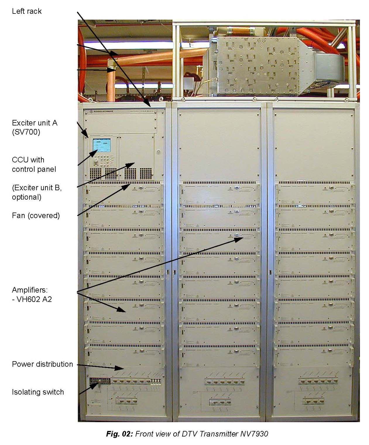
Click to zoom
Application Details
- Equipment Class
- TNB - Licensed Non-Broadcast Station Transmitter
- Date of Grant
- Oct 16, 2006
- Application Purpose
- Original Equipment
- Date of Application
- Aug 13, 2006
- Equipment Note
- DMQ-T Sender (Transmitter)
- Frequency Range
- 716.00000000 - 722.00000000
- Company
- Rohde & Schwarz Inc
- Country
- United States
Documents & Files
Document Text
Text extracted from the exhibit documents filed with the FCC. Open a document above to read the original.
Users Manual
NV7000 series Transmitter FCC Certification Application Exhibit D 7 August 2K6 Page 1 E XHIBIT D NV7000 TRANSMITTER FAMILY SPECIFICATIONS NV7000 series Transmitter FCC Certification Application Exhibit D 7 August 2K6 Page 2 Transmitter Family NV7000 General Specifications Frequency range 470 to 860 MHz Standards EN 300 744 DVB band width 6, 7 or 8 MHz, software limited to 6 MHz for operation in USA SFN function to TS 101 191 Permissible VSWR s ≤ 1,3 (switch-off at 1,3) RF Output Module (VH602A2) (Final RF Stage) LDMOS transistors, 8-pairs for a total of 16 devices per amplifier module Final stage DC operating parameters are: E = 32-volts DC, I ≈ 3.3 am- peres/transistor, 6.6 amperes/pair, 53-amperes/module. Total power output is 440-watts for OFDM/MediaFLO modulation waveform. Coolant Demineralized water, or a mixture of same with Antifrogen N or Chevron- Texaco Dexcool or Prestone Extended Life. Please consult the pump assembly documentation from for specific infor- mation. Max. installation altitude 2000 meters (6,562-feet) above sea level [>3000 meters (>9,840-feet) operation available on request] Operating temperature range in transmitter room +5° Celsius to +45° Celsius (+40° Fahrenheit to +113° Fahrenheit) when outside temperature is -30° Celsius to +50° Celsius ( -22° Fahrenheit to +122° Fahrenheit) Max. relative humidity 95% non condensing EMC to ETS 300 447 and FCC Part 2 and Part 15. AC supply voltage 400“Y”/230 Volts ±15% AC line frequency 50 Hz/60 Hz, ±2% Power factor min. 0.9 Total noise level <60 dBA Frequency processing Synthesizer adjustable between 112.5 MHz and 900 MHz Step width 1 Hz Connection internal OCXO (10 MHz), internal GPS receiver (optional) or external Transfer characteristics Transmission parameters to ETS 300 774 Input data rate 5 to 40 Mbit/s (dep. on operating mode) Frequency response f 0 ±3,805 MHz ≤ 1 dB NV7000 series Transmitter FCC Certification Application Exhibit D 7 August 2K6 Page 3 Transmitter Family NV7000 General Specifications (continued) Intermodulation suppression DVB band width 8 MHz at f 0 ±4.2 MHz (without band pass filter) ≤ -36 dB (with pre correction) DVB band width 7 MHz at f 0 ±3.7 MHz (without band pass filter) (information included for reference only!) ≤ -36 dB (with pre correction) Parasitic emissions not detectable Compliance with spectrum mask Please consult Exhibits F and S MER ≥ 33 dB at Tx output Spurious emissions Harmonics ≥ -70 dB (with output band pass filter) Noise power density ≥ 130 dBc/Hz Connectors ASI A 1/2 (LP) MPEG2; ASI, BNC, 75 W; input A or main and stand-by path for low priority data stream ASI B 1/2 (HP) MPEG2; ASI, BNC, 75 W; input B or main and stand-by path for high priority data stream Reference frequency 1, 5 or 10 MHz, 0.1 to 5 V pp or TTL, BNC Reference pulse 1 Hz, TTL, BNC, evaluating rising edge GPS antenna for integrated GPS receiver (option), active GPS antenna, BNC, 50 W, remote feed 5 V DC RF test points N or SMA RF output Please refer to next page and appropriate model number Transmitter protection facilities Remote Control Modulating signal input monitoring circuit Serial RS-232 interface Reflection (VSWR ) monitoring circuit Serial RS-485 interface / Bitbus to IEC/IEEE 864-1 (option) Amplifier and power supply monitoring cir- cuit Serial interface: NetLink software (optional) NetCCU 700 for Ethernet 10baseT with WEB Server, SNMP in- terface, or both (optional) Over temperature monitoring of power am- plifier Parallel interface (optional) Inlet temperature monitoring of coolant AC supply voltage monitoring circuit Smoke alarm (optional) NV7000 series Transmitter FCC Certification Application Exhibit D 7 August 2K6 Page 4 Model NV7080 NV7130 NV7170 NV7250 NV7340 NV7500 NV7640 NV7700 NV7930 No. of amplifiers 2 3 4 6 8 12 16 18 24 No. of Cabinets 1 1 1 1 1 2 2 3 3 Output power at Tx output E/V versions shoulder –36 dB at F o ±4,3 MHz 850 W 1280 W 1700 W 2560 W 3400 W 4890 W 6530 W 7320 W 9760 W shoulder –35 dB at F o ±4,3 MHz 870 W 1310 W 1740 W 2620 W 3480 W 5010 W 6680 W 7500 W 10000 W Power consumption TX w/o cooling system From Ch 21 to Ch 60 approx. 5 kW 7 kW 9,5 kW 13,5 kW 18,5 kW 28,5 kW 38,5 kW 42,5 kW 57 kW From Ch 61 to Ch 69 linear up to 10% higher Power consumption of cooling system Pump assembly approx. 0,8 kW 0,8 kW 0,8 kW 0,8 kW 1 kW 1,4 kW 2 kW 2 kW 2,8 kW Heat exchanger approx. 0,5 kW 0,5 kW 0,8 kW 0,8 kW 1,2 kW 1,2 kW 2,4 kW 2,4 kW 2,4 kW Cooling liquid volume flow rate (approx.) 15 l/min 22.5 l/ min 30 l/min 45 l/min 60 l/min 90 l/min 120 l/min 135 l/min 180 l/min 3.3 gal/ min 5 gal/ min 6.6 gal/ min 9.9 gal/ min 13.2 gal/ min 19.8 gal/ min 26.4 gal/ min 29.7 gal/ min 39.6 gal/ min Heat dissipation into room approx. 0,5 kW 0,8 kW 0,8 kW 1,0 kW 1,2 kW 2,0 kW 2,5 kW 3,0 kW 4,0 kW Heat dissipation guided outside approx. 4 kW 5 kW 7 kW 10 kW 14 kW 22 kW 30 kW 33 kW 44 kW Dimensions (H x D x W) E/V versions: 2167 mm x 1200 mm x 630 mm 630 mm 630 mm 630 mm 630 mm 1260 mm 1260 mm 1890 mm 1890 mm (H x D x W): 85.3" x 47.3" x 24.8" 24.8" 24.8" 24.8" 24.8" 49.6" 49.6" 74.4" 74.4" Weight (w/o transport packing and cooling system) E/V versions approx. 380 kg 410 kg 440 kg 490 kg 560 kg 1000 kg 1800 kg 1500 kg 2000 kg 838 lbs 904 lbs 970 lbs 1080 lbs 1235 lbs 2205 lbs 3968 lbs 3907 lbs 4409 lbs Weight (incl. transport packing and cooling system) 1180 kg 1220 kg 1380 kg 1480 kg 1600 kg 2700 kg 4880 kg 4440 kg 5920 kg for sea-/air freight, E/V approx. 2601 lbs 2690 lbs 3042 lbs 3263 lbs 5327 lbs 5953 lbs 10759 lbs 9789 lbs 13051 lbs RF output EIA EIA EIA EIA EIA EIA EIA EIA EIA 1-5/8" 1-5/8" 1-5/8" 1-5/8" 1-5/8" 3-1/8" 3-1/8" 3-1/8" 3-1/8" Transmitter Family NV7000 Model Specific Information
Attestation Statements
NV7000 series Transmitter FCC Certification Application 7 August 2K6 C ERTIFICATION OF DATA 47CFR§2.911 (A - G) This application contains three different measurement reports. Exhibit F, Siemens Test Report U0TG0004, contains measurements that were conducted by an FCC authorized testing facility, registration number 90932. The capabilities and qualifications of that facility are a matter of record before the Commission. Exhibit G, NV700 Exciter Temperature Stability Report, contains measure- ment data taken by, or under the supervision of Mr. Cornelius Heinemann. Mr. Heinemann is the principal designer of the exciter unit subjected to the tests and is familiar with the testing methods necessary to gather the included data. The measurements were taken at the Rohde & Schwarz environmental testing facilities located within the company’s main business campus in Munich, Ger- many. The facility is well maintained and all instruments used in the measure- ments are current in their calibrations. Exhibit H, NV7930 Factory Acceptance Test contains measurements taken at Rohde & Schwarz’s Werk Teisnach, in Teisnach, Germany; the main manufac- turing and testing facility for transmitters. All of the engineers involved in transmitter testing at that facility are well versed in the methodology required to take the measurements presented. All of the test instrumentation used to ac- quire the data are current in calibration. Given the above, I believe the measured data presented within this application to be true and accurate to the best of the knowledge and belief of the various engineers making the measurements. Respectfully, Program/Project Manager
Cover Letter(s)
APPLICATION FOR EQUIPMENT CERTIFICATION FCC FORM 731 AND S UPPORTING DOCUMENTATION SUBMITTED TO: FEDERAL COMMUNICATIONS COMMISSION EQUIPMENT APPROVAL SERVICES P OST OFFICE BOX 358318 PITTSBURGH, PA 15251-5315 F OR: R OHDE & SCHWARZ NV7000 SERIES TRANSMITTER FAMILY ( SELECT MODELS) 7 A UGUST 2006 NV7000 series Transmitter FCC Certification Application 31 July 2K6 Table of Contents Exhibit Description Confidentiality Requested Cover Letter No A Parts List and Tune Up Procedure No B Operational Description No C Block Diagrams Yes D NV7000 Transmitter Family General Specifications No E ID Labels and Location Description No F Siemens Laboratory Report No G NV700 Exciter Temperature Stability Test Report No H Rohde & Schwarz Factory Test Report Yes J NetCCU 700 Manual Yes K NV7930 Installation and Commissioning Manual (10 Parts) Yes L NV7930 DMQ-T Operating Manual (Preliminary) (3 Parts) Yes M NV7930 DMQ-T Service Manual, Volume 1 (5 Parts) Yes N NV7930 DMQ-T Service Manual, Volume 2 (3 Parts) Yes P Exciter Printed Circuit Board Photos Yes R Transmitter Printed Circuit Board Photos (includes photo of NetCCU 700 Chassis) Yes S Qualcomm MediaFLO Modulation Overview Yes T Qualcomm Source Control Document for Channel (“Mask”) Filter Yes Statements of Qualifications for Measurements No Table of Contents and Application Overview No Request for Confidentiality No NV7000 series Transmitter FCC Certification Application 31 July 2K6 Summary of Application for Certification of Equipment As stated in the cover letter Rohde & Schwarz, Inc. is hereby applying for Equipment Cer- tification for select models of the NV7000 family of UHF solid state transmitters. This is to permit licensed operation of those select models pursuant to 47CFR§27.51. To that end we are electronically submitting an Application for Equipment Authorization, FCC form 731 as specified by 47CFR§27.1033, Application for Certification. Along with that form we are including as Exhibits the requisite documentation, including reports of various measure- ments conducted in accordance with 47CFR§2, that demonstrate compliance with the perti- nent sections of 47CFR§27 and 47CFR§2. 47CFR§2.1033(c) APPLICATION FOR CERTIFICATION INFORMATION Mailing Address: FCC Identifier: Please refer to Exhibit E of this Application, FCC ID Label and Placement, for examples of the FCC ID labels and the manufacturer’s information labels for the NV7000 family of transmitters. Note that not all output power levels of the NV7000 family are considered in this Application for Certification. Therefore we have elected to request a separate FCC ID number for each of the individual model numbers (power levels) that are included. Installation and Commissioning Manual: Operating Manual: Rohde & Schwarz, Inc Rohde & Schwarz, GmbH & Co. KG 8661A Robert Fulton Drive Broadcasting Division Columbia, MD 21046-2255 Mühldorfstraße 15 D-81671 München Federal Republic of Germany Exhibit L is a copy of the NV7930 Installation and Commissioning Man- ual. This manual contains complete, detailed instructions to guide the end user from receiving the unit up to the point of turn-on, including instruc- tions on making all necessary adjustment and calibration procedures to that end. Virtually all of the information presented is applicable to all NV7000 series Transmitter FCC Certification Application 31 July 2K6 transmitters in the NV7000 family. The manual does cover additional steps required for commissioning of the three cabinet models that are not required for the smaller units but those differences are readily apparent. Exhibit M is the NV7930 Operating Manual. It includes quite detailed information for the configuration and operation of the transmitter. Where appropriate, the information is dupli- cated from NV7930 Installation and Commissioning Manual. Exhibit K is the Commissioning and Operating Manual for the optional NetCCU 700. While not a required part of the transmitter, the NV7930 unit tested for this application included this unit so the manual is provided for reference. Type or Types of Emission: 6M00W7W for this application. Please refer to Exhibit S, MediaFLO Modulation Overview for a discussion of the modula- tion methodology employed. Frequency Range: 470-mHz to 860-mHz Please refer to Exhibit D, NV7000 Transmitter Family General Specifications, for a complete listing of specifications for all models in the NV7000 transmitter family covered by this application. Range of Operating Power Values or Specific Operating Power Levels: The various transmitters covered under this application and their rated power output levels are shown in Exhibit D, NV7000 Transmitter Family General Specifications. The output power level of any transmitter in the family can be reduced to any reasonable level (100% to approximately 20%) that may be required during installation. (Widely varying output power during operation is not considered to be a routine occurrence.) Please see Exhibit K, NV7930 Installation and Commissioning Manual, Chapter 4, page 29 (3.2.1.3) and Exhibit L, NV7930 Operating Manual, Chapter 5, page 48 (1.7) for instructions on making the ad- justment. Maximum Power Rating: Refer to Exhibit D, NV7000 Family General Specifications, for the power rating for each transmitter. NV7000 series Transmitter FCC Certification Application 31 July 2K6 Final Stage DC Voltage and Currents: VH602A2 UHF Power Amplifier Module LDMOS transistors, 8-pairs for a total of 16 devices per amplifier module. Final stage DC operation parameters are: E = 32-volts, DC, I ≈ 3.3 amperes/transistor, 6.6 amperes/pair, 53-amperes/module. Total power output is 440-watts with OFDM/MediaFLO modulation waveform. Tune-Up Procedure: As the transmitters in the NV7000 family are broadband in design there is no tune-up proce- dure, per se. Exhibit A, Parts List and Tune Up Procedure, gives a brief outline of the com- missioning process needed to prepare a transmitter for operation. Commissioning and ad- justment are fur…
Text truncated - open the document above for the full version.
Cover Letter(s)
NV7000 series Transmitter FCC Certification Application 7 August 2K6 Request for Confidentiality Pursuant to 47CFR§0.459 we hereby request that the Exhibits marked on the Table of Con- tents as “Confidentiality Requested”, and also marked as “Confidential” on their respective cover pages, be withheld from public inspection. Each of these Exhibits contain informa- tion that is of a proprietary nature to our company and possibly to our customers. Informa- tion that could be obtained from the cited Exhibits, commonly referred to as “Trade Se- crets”, includes printed circuit trace routing, component selection, RF circuit “broadbanding” techniques, mechanical construction layouts and modulation methods. The confidentiality of such information is carefully guarded within our company, and only shared when further disclosure is restricted by binding agreement. Additional proprietary information is contained within drawings, schematics and equip- ment configuration instructions that’s normally supplied to customers only after their pur- chase of the described equipment. Our customers, after having made such purchases, have no reason to share the documents with other parties and, in some cases, may be restricted from doing so by binding agreement. Additionally those documents are normally supplied as hard copies as part of the equipment’s documentation, and often in a size that is difficult to duplicate with standard office equipment. We are therefore concerned that in the event the above described information were to be made available in a public forum, particularly one as easy to access as the World Wide Web, then our competitors, or those of our customers, could easily obtain and use it to compromise our ability, and that of our customers, to maintain our respective competitive positions in “the marketplace”, worldwide. We therefore respectfully ask that you honor our request to maintain that confidentiality in regard to the selected documents. To that end we’ve attempted to group the sensitive information into select Exhibits and have marked the cover pages of those Exhibits, and their respective entries in the Table of Contents as described above. Thank you very much for your consideration. Sincerely, Richard Sweitzer Program/Project Manager 1-703-779-1095 (office) 1-410-910-7843 (fax) [email protected]
Cover Letter(s)
APPLICATION FOR EQUIPMENT CERTIFICATION FCC FORM 731 AND S UPPORTING DOCUMENTATION SUBMITTED TO: FEDERAL COMMUNICATIONS COMMISSION EQUIPMENT APPROVAL SERVICES P OST OFFICE BOX 358318 PITTSBURGH, PA 15251-5315 F OR: R OHDE & SCHWARZ NV7000 SERIES TRANSMITTER FAMILY ( SELECT MODELS) 7 A UGUST 2006 NV7000 series Transmitter FCC Certification Application 7 August 2K6 Table of Contents Exhibit Description Confidentiality Requested Cover Letter No A Parts List and Tune Up Procedure No B Operational Description No C Block Diagrams Yes D NV7000 Transmitter Family General Specifications No E ID Labels and Location Description No F Siemens Laboratory Report No G NV700 Exciter Temperature Stability Test Report No H Rohde & Schwarz Factory Test Report No J NetCCU 700 Manual Yes K NV7930 Installation and Commissioning Manual (10 Parts) Yes L NV7930 DMQ-T Operating Manual (Preliminary) (3 Parts) Yes M NV7930 DMQ-T Service Manual, Volume 1 (5 Parts) Yes N NV7930 DMQ-T Service Manual, Volume 2 (3 Parts) Yes P Exciter Printed Circuit Board Photos Yes R Transmitter Printed Circuit Board Photos (includes photo of NetCCU 700 Chassis) Yes S Qualcomm MediaFLO Modulation Overview Yes T Qualcomm Source Control Document for Channel (“Mask”) Filter Yes Certification of Data No Table of Contents and Application Overview No Request for Confidentiality No NV7000 series Transmitter FCC Certification Application 7 August 2K6 Summary of Application for Certification of Equipment As stated in the cover letter Rohde & Schwarz, Inc. is hereby applying for Equipment Cer- tification for select models of the NV7000 family of UHF solid state transmitters. This is to permit licensed operation of those select models pursuant to 47CFR§27.51. To that end we are electronically submitting an Application for Equipment Authorization, FCC form 731 as specified by 47CFR§27.1033, Application for Certification. Along with that form we are including as Exhibits the requisite documentation, including reports of various measure- ments conducted in accordance with 47CFR§2, that demonstrate compliance with the perti- nent sections of 47CFR§27 and 47CFR§2. 47CFR§2.1033(c) APPLICATION FOR CERTIFICATION INFORMATION Mailing Address: FCC Identifier: Please refer to Exhibit E of this Application, FCC ID Label and Placement, for examples of the FCC ID labels and the manufacturer’s information labels for the NV7000 family of transmitters. Note that not all output power levels of the NV7000 family are considered in this Application for Certification. Therefore we have elected to request a separate FCC ID number for each of the individual model numbers (power levels) that are included. Installation and Commissioning Manual: Operating Manual: Rohde & Schwarz, Inc Rohde & Schwarz, GmbH & Co. KG 8661A Robert Fulton Drive Broadcasting Division Columbia, MD 21046-2255 Mühldorfstraße 15 D-81671 München Federal Republic of Germany Exhibit L is a copy of the NV7930 Installation and Commissioning Man- ual. This manual contains complete, detailed instructions to guide the end user from receiving the unit up to the point of turn-on, including instruc- tions on making all necessary adjustment and calibration procedures to that end. Virtually all of the information presented is applicable to all NV7000 series Transmitter FCC Certification Application 7 August 2K6 transmitters in the NV7000 family. The manual does cover additional steps required for commissioning of the three cabinet models that are not required for the smaller units but those differences are readily apparent. Exhibit M is the NV7930 Operating Manual. It includes quite detailed information for the configuration and operation of the transmitter. Where appropriate, the information is dupli- cated from NV7930 Installation and Commissioning Manual. Exhibit K is the Commissioning and Operating Manual for the optional NetCCU 700. While not a required part of the transmitter, the NV7930 unit tested for this application included this unit so the manual is provided for reference. Type or Types of Emission: 6M00W7W for this application. Please refer to Exhibit S, MediaFLO Modulation Overview for a discussion of the modula- tion methodology employed. Frequency Range: 470-mHz to 860-mHz Please refer to Exhibit D, NV7000 Transmitter Family General Specifications, for a complete listing of specifications for all models in the NV7000 transmitter family covered by this application. Range of Operating Power Values or Specific Operating Power Levels: The various transmitters covered under this application and their rated power output levels are shown in Exhibit D, NV7000 Transmitter Family General Specifications. The output power level of any transmitter in the family can be reduced to any reasonable level (100% to approximately 20%) that may be required during installation. (Widely varying output power during operation is not considered to be a routine occurrence.) Please see Exhibit K, NV7930 Installation and Commissioning Manual, Chapter 4, page 29 (3.2.1.3) and Exhibit L, NV7930 Operating Manual, Chapter 5, page 48 (1.7) for instructions on making the ad- justment. Maximum Power Rating: Refer to Exhibit D, NV7000 Family General Specifications, for the power rating for each transmitter. NV7000 series Transmitter FCC Certification Application 7 August 2K6 Final Stage DC Voltage and Currents: VH602A2 UHF Power Amplifier Module LDMOS transistors, 8-pairs for a total of 16 devices per amplifier module. Final stage DC operation parameters are: E = 32-volts, DC, I ≈ 3.3 amperes/transistor, 6.6 amperes/pair, 53-amperes/module. Total power output is 440-watts with OFDM/MediaFLO modulation waveform. Tune-Up Procedure: As the transmitters in the NV7000 family are broadband in design there is no tune-up proce- dure, per se. Exhibit A, Parts List and Tune Up Procedure, gives a brief outline of the com- missioning process needed to prepare a transmitter for operation. Commissioning and ad- justment are further described in int…
Text truncated - open the document above for the full version.
External Photos
NV7000 series Transmitter FCC Certification Application Exhibit E 7 August 2K6 Page 1 E XHIBIT E I DENTIFICATION LABEL INFORMATION AND EXTERIOR P HOTOS NV7930E/V OFDM/DMQ-T (M EDIAFLO) 9.3- KILOWATT TRANSMITTER (FCC ID L ABEL EXAMPLES INCLUDED FOR LOWER POWER MODELS AS WELL.) NV7000 series Transmitter FCC Certification Application Exhibit E 7 August 2K6 Page 2 Sample FCC Identification Labels for NV7930E/V and for lower power models. For NV7080V/E, 850-watts output power For NV7130V/E, 1,280-watts output power For NV7170V/E, 1,700-watts output power For NV7250V/E, 2,560-watts output power For NV7340V/E, 3,400-watts output power For NV7500V/E, 4,890-watts output power For NV7640V/E, 6,530-watts output power For NV7700V/E, 7,320-watts output power For NV7930V/E, 9,760-watts output power NV7000 series Transmitter FCC Certification Application Exhibit E 7 August 2K6 Page 3 Example of Manufacturers ID Labels for NV7000 series. NV7000 series Transmitter FCC Certification Application Exhibit E 7 August 2K6 Page 4 Front View of NV7930 Transmitter Manufacturers ID Label Approxi- mate Location FCC ID Label Location NV7000 series Transmitter FCC Certification Application Exhibit E 7 August 2K6 Page 5 Rear View of NV7930 Transmitter with Covers Removed
ID Label/Location Info
NV7000 series Transmitter FCC Certification Application Exhibit E 7 August 2K6 Page 1 E XHIBIT E I DENTIFICATION LABEL INFORMATION AND EXTERIOR P HOTOS NV7930E/V OFDM/DMQ-T (M EDIAFLO) 9.3- KILOWATT TRANSMITTER (FCC ID L ABEL EXAMPLES INCLUDED FOR LOWER POWER MODELS AS WELL.) NV7000 series Transmitter FCC Certification Application Exhibit E 7 August 2K6 Page 2 Sample FCC Identification Labels for NV7930E/V and for lower power models. For NV7080V/E, 850-watts output power For NV7130V/E, 1,280-watts output power For NV7170V/E, 1,700-watts output power For NV7250V/E, 2,560-watts output power For NV7340V/E, 3,400-watts output power For NV7500V/E, 4,890-watts output power For NV7640V/E, 6,530-watts output power For NV7700V/E, 7,320-watts output power For NV7930V/E, 9,760-watts output power NV7000 series Transmitter FCC Certification Application Exhibit E 7 August 2K6 Page 3 Example of Manufacturers ID Labels for NV7000 series. NV7000 series Transmitter FCC Certification Application Exhibit E 7 August 2K6 Page 4 Front View of NV7930 Transmitter Manufacturers ID Label Approxi- mate Location FCC ID Label Location NV7000 series Transmitter FCC Certification Application Exhibit E 7 August 2K6 Page 5 Rear View of NV7930 Transmitter with Covers Removed
ID Label/Location Info
NV7000 series Transmitter FCC Certification Application Exhibit E 25 August 2K6 Page 1 E XHIBIT E—REVISED I DENTIFICATION LABEL INFORMATION AND EXTERIOR P HOTOS NV7930E/V OFDM/DMQ-T (M EDIAFLO) 9.3- KILOWATT TRANSMITTER (FCC ID L ABEL EXAMPLES INCLUDED FOR LOWER POWER MODELS AS WELL.) NV7000 series Transmitter FCC Certification Application Exhibit E 25 August 2K6 Page 2 Sample FCC Identification Labels for NV7930E/V (and for lower power models). For NV7930V/E; 9,760-watts output power (enlarged view for clarity) For NV7700V/E; 7,320-watts output power (enlarged view for clarity) For NV7640V/E; 6,530-watts output power (enlarged view for clarity) For NV7500V/E, 4,890-watts output power (enlarged view for clarity) For NV7340V/E, 3,400-watts output power (enlarged view for clarity) FCC ID: HFLNV7930 FCC ID: HFLNV7700 FCC ID: HFLNV7640 FCC ID: HFLNV7500 FCC ID: HFLNV7340 NV7000 series Transmitter FCC Certification Application Exhibit E 25 August 2K6 Page 3 For NV7250V/E; 2,560-watts output power (enlarged view for clarity) For NV7170V/E; 1,700-watts output power (enlarged view for clarity) For NV7130V/E; 1,280-watts output power (enlarged view for clarity) For NV7080V/E, 850-watts output power (enlarged view for clarity) View of sample label at approximate actual size FCC ID: HFLNV7250 FCC ID: HFLNV7170 FCC ID: HFLNV7130 FCC ID: HFLNV7080 ≈ 2” (51 mm) ≈ 5/8” (16 mm) FCC ID: HFLNVXXXX NV7000 series Transmitter FCC Certification Application Exhibit E 25 August 2K6 Page 4 Example of Manufacturers ID Labels for NV7000 series. NV7000 series Transmitter FCC Certification Application Exhibit E 25 August 2K6 Page 5 Front View of NV7930 Transmitter Manufacturers ID Label Approxi- mate Location FCC ID Label Location NV7000 series Transmitter FCC Certification Application Exhibit E 25 August 2K6 Page 6 Rear View of NV7930 Transmitter with Cover Panels Removed
Operational Description
NV7000 series Transmitter FCC Certification Application Exhibit B 7 August 2K6 Page 1 E XHIBIT B O PERATIONAL DESCRIPTION NV7930E/V OFDM/DMQ-T (M EDIAFLO) 9.3- KILOWATT TRANSMITTER NV7000 series Transmitter FCC Certification Application Exhibit B 7 August 2K6 Page 2 SV7000 Transmitter Operational Description/Functional Overview Following is a brief description of the NV7000 series transmitter. A much more detailed description of the transmitters’ functionality, operation and mechanical layout can be found in Exhibit K, NV7930 Installation and Commissioning Manual; Exhibit L, NV7930 Operating Manual; Exhibit M, NV7930 Maintenance Man- ual Volume 1; and Exhibit N, NV7930 Maintenance Manual Volume 2 that accompany this application. The NV7000 series transmitter may be viewed in two parts. The exciter portion generates the desired carrier frequency and modulates it with the intelligent information of interest. The power amplifiers increase the ex- citer’s output signal level to that desired for transmission. SV700 Exciter: The SV 700 processes the received MPEG transport stream in ASI or SMPTE 310 format. The utilized data packets are extracted from the data stream and coded and modulated in line with ETS 300744. The OFDM/ DMQ-T (MediaFLO) signal is then generated at the transmit frequency and fed to the output stage. Since the exciter is able to synchronize the output signal to an external reference (e.g. GPS = global positioning system) with a view to frequency and time, the transmitter can be used in MFNs (multi-frequency networks = single transmitters operating at different frequencies) and in SFNs (single frequency networks). The exciter comprises the following, modules: encoder, equalizer/pre-corrector, modulator and synthesizer. The modules are interconnected via the motherboard and are powered from their own switching power supply (one per exciter). Encoder: The encoder accepts up to two MPEG transport streams (TS). The selected input signal is first read into a buffer (FIFO) for clock decoupling and then coded and modulated according to the DVB standard. Baseband signals are thus obtained which are forwarded to the equalizer. At the same time the encoder evaluates the MIP (megaframe initialization packet) and so synchronizes the transmission time of the data packets with the aid of a time reference like GPS (SFN automatic). The DVB / transmission parameters can also be read from the MIP and used to configure the encoder (TPS automatic). The encoder also contains a microcontroller which drives the whole exciter and handles communication with the CCU (central control unit). A program memory is provided as a peripheral for the microcontroller. This means that all the exciter firmware and software is stored at one location and an update can be performed via the serial interface without replacing any hardware. The coder extension board is an add-on encoder module. With this option proprietary modulation standards such as DMQ-T (MediaFLO) can easily be installed on the exciter by only transferring an FPGA configuration file to the unit. Equalizer/Pre-Corrector: The equalizer/pre-corrector consists of a linear equalizer and a non linear equalizer. Pre- correction is performed at digital baseband level. The linear pre-corrector corrects the phase and frequency response of any power filter that is used. The non linear equalizer separately corrects the amplitude and the phase of the time signal as a function of ampli- tude. A limiter can be added to linearity pre-correction to optimize the efficiency of the transmitter. NV7000 series Transmitter FCC Certification Application Exhibit B 7 August 2K6 Page 3 An optional data recorder allows recording of the RF signal and thus automation of the pre-correction operation. The pre-emphasized digital baseband signals are subsequently converted into analog signals and applied to the …
Text truncated - open the document above for the full version.
Contact Information
Applicant
Erik Balladeres
Test Firm
SGS Germany GmbHJosef Bauer
Technical Specifications
| # | Rule Parts | Frequency Range | Power Output | Emission | Tolerance |
|---|---|---|---|---|---|
| 1 | 27 | 716 MHz - 722 MHz | 9760 W | 6M00W7W | 2000.0000000000 Hz |
Other Applications from Rohde & Schwarz Inc
HFLTMU91
Aug 18, 2014500 Watt UHF ATSC Transmitter
Equipment Class
TBC - Licensed Broadcast Station Transmitter
HFLTMU925
Jul 21, 2014UHF DTV ATSC 1KW TO 2.5 KW TRANSMITTER FAMILY
Equipment Class
TBC - Licensed Broadcast Station Transmitter
HFLNV830X
May 22, 2012UHF 1.8kW maximum Digital TV transmitter
Equipment Class
TBC - Licensed Broadcast Station Transmitter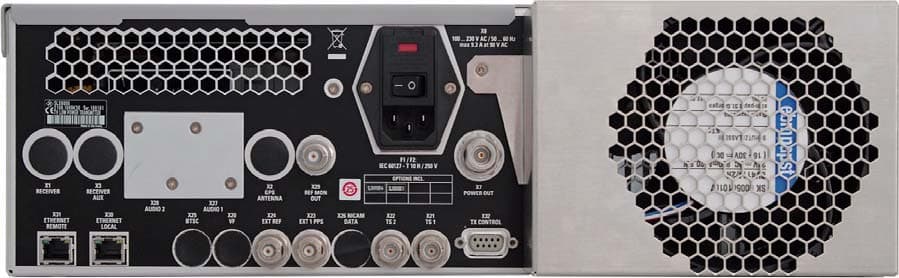
HFLSLV8000
Jan 05, 2011SLV8000 Low Power Transmitter
Equipment Class
TBC - Licensed Broadcast Station Transmitter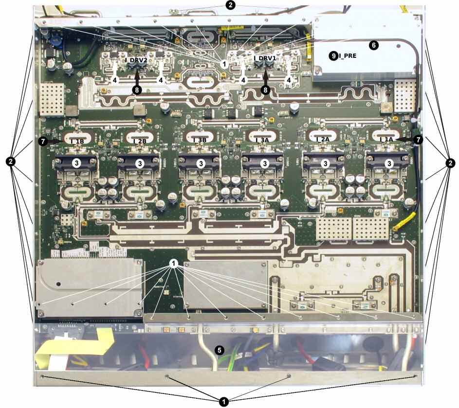
HFLSCV8000
May 04, 2010SCV8000
Equipment Class
TBC - Licensed Broadcast Station Transmitter