HFS-A100PCS Band GSM Phone
Quanta Computer Inc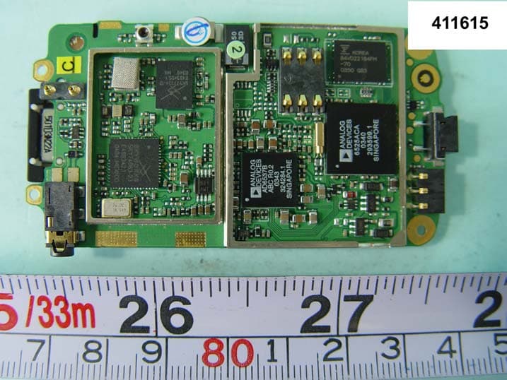
Click to zoom
Application Details
- Equipment Class
- PCE - PCS Licensed Transmitter held to ear
- Date of Grant
- Mar 30, 2004
- Application Purpose
- Original Equipment
- Date of Application
- Mar 30, 2004
- Equipment Note
- PCS Band GSM Phone
- Frequency Range
- 1850.20000000 - 1909.80000000
- Company
- Quanta Computer Inc
- Country
- Taiwan
Documents & Files
Document Text
Text extracted from the exhibit documents filed with the FCC. Open a document above to read the original.
Users Manual
FCC Regulations Conditions of Use Operation of this Panasonic mobile phone is subject to the following two conditions; (1) this device may not cause harmful interference, and (2) this device must accept any interference received, including interference that may cause undesired operation. This Panasonic mobile phone generates, uses and can radiate radio frequency energy and, if not installed and used in accordance with the instructions, may cause harmful interference to radio communications. If this device does cause harmful interference to radio or television reception, which can be determined by turning the device on and off, the user is encouraged to try to correct the interference by one or more of the following measures: 1). Reorient or relocate the receiving antenna. 2). Increase the distance between the device and receiver. 3). Connect the device into an outlet on a circuit different from that to which the receiver is connected. 4). Consult the dealer or an experienced radio/TV technician for help. The radiated output power of this internal wireless radio is far below the FCC radio frequency exposure limits. Nevertheless, the wireless radio shall be used in such a manner that the radio is 2.5 cm or further from the human body. However, the user of wireless radios may be restricted in some places or situations, such as aboard airplanes. If you are unsure of restrictions, you are encouraged to ask for authorization before turning on the wireless radio. Several restrictions and cautions of using mobile phone are listed in the Important Information. FCC RF EXPOSURE INFORMATION Read this information before using your handset In August 1996 the Federal Communication Commission (FCC) of the United States with its action in Report and Order FCC 96-326 adopted an updated safety standard for human exposure to radio frequency (RF) electromagnetic energy emitted by FCC regulated transmitters. Those guidelines are consistent with the safety standard previously set by both U.S and international standards bodies. The design of this phone complies with the FCC guidelines and these international standards. Use only the supplied or an approved antenna. Unauthorized antennas, modifications, or attachments could impair call quality, damage the phone, or result in violation of FCC regulations. Do not use the phone with a damaged antenna. If a damaged antenna comes into contact with the skin, a minor burn may result. Please contact your local dealer for replacement antenna. Body-worn Operation This device was tested for typical body-worn operations. To comply with FCC RF exposure requirements, a minimum separation distance of 0.6 inches (1.5 cm) must be maintained between the user’s body and the handset, including the antenna. Third-party belt-clips, holsters, and similar accessories used by this device should not contain any metallic components. Body-worn accessories that do not meet these requirements may not comply with FCC RF exposure requirements and should be avoided. For more information about RF exposure, please visit the FCC website at www.fcc.gov
Users Manual
Getting Started 7 Getting Started Fitting and removing the battery Before removing the battery, ensure that the phone is switched off and the charger is disconnected from the phone. Remove the battery compartment cover. Insert the battery ensuring the 3 gold Contacts align with the 3 gold pins in the phone. Push and hold the release latch toward the top of the phone then lift the battery out . Removing the battery Fitting the battery A100_OI_English.book Page 7 Monday, March 8, 2004 3:10 PM 8 Getting Started Fitting and removing the SIM The SIM is located under the battery. Charging the battery Connecting and disconnecting the Travel Charger The battery must be fitted in the phone before the charger is connected. Insert the Charger Connector into the socket at the base of the phone before connecting the Charger to the Mains socket-outlet. Once Connected the Battery Level Indicator will start scrolling. (See page 9 "Battery level indicator") It is recommended to charge the battery for a minimum of 4 hours before first use. NOTE: DO NOT force the connector as this may damage the phone and/or the charger. If the battery has been deeply discharged, it may take several minutes before the Battery Level Indicator is displayed. Fitting the SIM Removing the SIM Ensure the gold contacts are facing downwards before sliding the SIM into the SIM holder. While holding the tab down slide the SIM out. A100_OI_English.book Page 8 Monday, March 8, 2004 3:10 PM Getting Started 9 When charging is complete disconnect the charger from the socket-outlet before removing the plug from the Phone. Battery level indicator Low battery power warning When the battery power is low, Battery is low message will be displayed. If this occurs during conversation, finish your call immediately. The power will automatically switch off after the warning tone. Fully recharge the battery. See "Charging the battery" on page 8. (Calls can be made and received while the phone is charging.) While chargingCharging complete Phone on >J Phone off A100_OI_English.book Page 9 Monday, March 8, 2004 3:10 PM 10 Getting Started Keys and display Ear Piece Personal Hands Free Connector Left Soft Key Performs functions indicated on the left side corner Send Key Answers/makes a call Charging Connector Display Silent Mode Key Press and hold to switch Silent Mode on/off Navi-key Scrolls/moves through menus Right Soft Key Cancels/exits Perform functions indicated on the right side corner Power/End Key Press and hold to switch your phone on/off A100_OI_English.book Page 10 Monday, March 8, 2004 3:10 PM Getting Started 11 Key functions Key Function 4 2-Way (up/down) Navi-key: Scrolls or moves through menus, text and phone numbers. In idle mode, press to activate "Contacts". A Left Soft key: Performs the functions indicated by text shown on the display. In idle mode, press to activate "Menu" display, or press and hold to activate"Profiles" menu. @ Right Soft key/Cancel or Exit key: Performs the functions indicated by text shown on the display. Mainly used to cancel and return to the previous menu level. In text entry mode, long press to delete text. In idle mode, press and hold to activate "Messages" menu. When receiving a call, press to mute the ringtone. #, " Numeric key pads: Enters numbers. Press and hold one of the keys from$to,to make a Hotkey dial. In text entry mode, enter text, numbers and characters. Press and hold #to enter a "+" (international access code) or "P" (extension number code). When you need to dial an extension number, dial the phone number first and press and hold # to add a "P" then enter the extension number. C Send Key: Makes a call or answers a call. In idle mode, press to check the last dialled list. In text entry mode, press to switch between input methods. D Power/End Key: Ends/rejects a call. During key operation, press to return to the previous display. In idle mode, press and hold to switch phone on/off. Press and hold to return to idle mode. ! Silent Mode Key: In idle mode, press and hold to switch the Silent Mode (Vibration on/Ring off) on and off. In text entry mode, press and hold to turn T9 smart English input mode on/off. During a call hold to press to turn the loud speaker on/off. A100_OI_English.book Page 11 Monday, March 8, 2004 3:10 PM 12 Getting Started Key functions (During a call) During a call minimal menu options are available by pressing the following key options. Key Function A Hands free, Conference call, Call transfer, Contacts list, Messages menu, Call status. @ Swaps between two calls. Put the call on hold. 1 Increases the volume while in a call. 5 Decreases the volume while in a call. #, !" Sends DTMF. A100_OI_English.book Page 12 Monday, March 8, 2004 3:10 PM Getting Started 13 Displays Idle display The clock appears on the display one minute after you press the last key. NOTE: All Screen images in the manual are simulated. NOTE: Some services described in this manual are network dependent or may only be available on a subscription basis. Some functions are SIM dependent. For more information contact your service provider. Status Icon Left Soft Key Selection Area Wallpaper Right Soft Key Selection Area A100_OI_English.book Page 13 Monday, March 8, 2004 3:10 PM 14 Getting Started Status icons The status icons are displayed or animated according to the currently activated functions. The Antenna, Signal and Battery icons are displayed when the handset is switched on and connected to a network. When the network level is zero, the Signal icon will not be displayed. Icon Indication OP Antenna and signal strength Registered to a non-home network - roaming G Call Diverts is on L Key Guard is enabled Message area is full Unread message is stored N Voice mail indicator (Voice mail is received) Alarm is set All tones or ring volume is off Vibration is on J K Battery full level low battery A100_OI_English.book Page 14 Monday, March 8, 2004 3:10 PM Getting Started 15 Symbols in the Manual SymbolsContent 154Pr…
Text truncated - open the document above for the full version.
Cover Letter(s)
Quanta Computer Incorporation Mar. 05, 2004 Federal Communications Commission Authorization and Evaluation Division FCC ID: HFS-A100 Confidentiality Request Pursuant to Sections 0.457 and 0.459 of the Commission’s Rules, the Applicant hereby requests confidential treatment of information accompanying this Application as outlined below: 1. Schematic RF circuitry diagram 2. Functional block diagram 3. Antenna Specification 4. Tune-up procedures 5. Part’s list The above materials contain trade secrets and proprietary information not customarily released to the public. The public disclosure of these matters might be harmful to the Applicant and provide unjustified benefits to its competitors. The Applicant understands that pursuant to Rule 0.457, disclosure of this Application and all accompanying documentation will not be made before the date of the Grant for this application. Sincerely, Johnathan Chen Johnathan Chen/ Product Manager Quanta Computer Inc.
External Photos
FCC TEST REPORT REPORT NO. : F411615 SPORTON International Inc. PAGE NUMBER : A1 OF A2 TEL : 886-2-2696-2468 ISSUED DATE : Mar. 25, 2004 FAX : 886-2-2696-2255 APPENDIX A. External Photographs of EUT FCC TEST REPORT REPORT NO. : F411615 SPORTON International Inc. PAGE NUMBER : A2 OF A2 TEL : 886-2-2696-2468 ISSUED DATE : Mar. 25, 2004 FAX : 886-2-2696-2255 FCC TEST REPORT REPORT NO. : F411615 SPORTON International Inc. PAGE NUMBER : A1 OF A5 TEL : 886-2-2696-2468 ISSUED DATE : Mar. 25, 2004 FAX : 886-2-2696-2255 APPENDIX B. Internal Photographs of EUT FCC TEST REPORT REPORT NO. : F411615 SPORTON International Inc. PAGE NUMBER : A2 OF A5 TEL : 886-2-2696-2468 ISSUED DATE : Mar. 25, 2004 FAX : 886-2-2696-2255 FCC TEST REPORT REPORT NO. : F411615 SPORTON International Inc. PAGE NUMBER : A3 OF A5 TEL : 886-2-2696-2468 ISSUED DATE : Mar. 25, 2004 FAX : 886-2-2696-2255 FCC TEST REPORT REPORT NO. : F411615 SPORTON International Inc. PAGE NUMBER : A4 OF A5 TEL : 886-2-2696-2468 ISSUED DATE : Mar. 25, 2004 FAX : 886-2-2696-2255 FCC TEST REPORT REPORT NO. : F411615 SPORTON International Inc. PAGE NUMBER : A5 OF A5 TEL : 886-2-2696-2468 ISSUED DATE : Mar. 25, 2004 FAX : 886-2-2696-2255 FCC TEST REPORT REPORT NO. : F411615 SPORTON International Inc. PAGE NUMBER : A1 OF A3 TEL : 886-2-2696-2468 ISSUED DATE : Mar. 25, 2004 FAX : 886-2-2696-2255 APPENDIX C. Setup Photograph For Radiated Emission FRONT VIEW BACK VIEW FCC TEST REPORT REPORT NO. : F411615 SPORTON International Inc. PAGE NUMBER : A2 OF A3 TEL : 886-2-2696-2468 ISSUED DATE : Mar. 25, 2004 FAX : 886-2-2696-2255 For Conducted Emission FRONT VIEW BACK VIEW FCC TEST REPORT REPORT NO. : F411615 SPORTON International Inc. PAGE NUMBER : A3 OF A3 TEL : 886-2-2696-2468 ISSUED DATE : Mar. 25, 2004 FAX : 886-2-2696-2255 REAR VIEW
Internal Photos
FCC TEST REPORT REPORT NO. : F411615 SPORTON International Inc. PAGE NUMBER : A1 OF A9 TEL : 886-2-2696-2468 ISSUED DATE : Mar. 25, 2004 FAX : 886-2-2696-2255 APPENDIX B. Internal Photographs of EUT FCC TEST REPORT REPORT NO. : F411615 SPORTON International Inc. PAGE NUMBER : A2 OF A9 TEL : 886-2-2696-2468 ISSUED DATE : Mar. 25, 2004 FAX : 886-2-2696-2255 FCC TEST REPORT REPORT NO. : F411615 SPORTON International Inc. PAGE NUMBER : A3 OF A9 TEL : 886-2-2696-2468 ISSUED DATE : Mar. 25, 2004 FAX : 886-2-2696-2255 FCC TEST REPORT REPORT NO. : F411615 SPORTON International Inc. PAGE NUMBER : A4 OF A9 TEL : 886-2-2696-2468 ISSUED DATE : Mar. 25, 2004 FAX : 886-2-2696-2255 FCC TEST REPORT REPORT NO. : F411615 SPORTON International Inc. PAGE NUMBER : A5 OF A9 TEL : 886-2-2696-2468 ISSUED DATE : Mar. 25, 2004 FAX : 886-2-2696-2255 FCC TEST REPORT REPORT NO. : F411615 SPORTON International Inc. PAGE NUMBER : A6 OF A9 TEL : 886-2-2696-2468 ISSUED DATE : Mar. 25, 2004 FAX : 886-2-2696-2255 FCC TEST REPORT REPORT NO. : F411615 SPORTON International Inc. PAGE NUMBER : A7 OF A9 TEL : 886-2-2696-2468 ISSUED DATE : Mar. 25, 2004 FAX : 886-2-2696-2255 FCC TEST REPORT REPORT NO. : F411615 SPORTON International Inc. PAGE NUMBER : A8 OF A9 TEL : 886-2-2696-2468 ISSUED DATE : Mar. 25, 2004 FAX : 886-2-2696-2255 FCC TEST REPORT REPORT NO. : F411615 SPORTON International Inc. PAGE NUMBER : A9 OF A9 TEL : 886-2-2696-2468 ISSUED DATE : Mar. 25, 2004 FAX : 886-2-2696-2255
Operational Description
FCC Regulations Conditions of Use Operation of this Panasonic mobile phone is subject to the following two conditions; (1) this device may not cause harmful interference, and (2) this device must accept any interference received, including interference that may cause undesired operation. This Panasonic mobile phone generates, uses and can radiate radio frequency energy and, if not installed and used in accordance with the instructions, may cause harmful interference to radio communications. If this device does cause harmful interference to radio or television reception, which can be determined by turning the device on and off, the user is encouraged to try to correct the interference by one or more of the following measures: 1). Reorient or relocate the receiving antenna. 2). Increase the distance between the device and receiver. 3). Connect the device into an outlet on a circuit different from that to which the receiver is connected. 4). Consult the dealer or an experienced radio/TV technician for help. The radiated output power of this internal wireless radio is far below the FCC radio frequency exposure limits. Nevertheless, the wireless radio shall be used in such a manner that the radio is 2.5 cm or further from the human body. However, the user of wireless radios may be restricted in some places or situations, such as aboard airplanes. If you are unsure of restrictions, you are encouraged to ask for authorization before turning on the wireless radio. Several restrictions and cautions of using mobile phone are listed in the Important Information. FCC RF EXPOSURE INFORMATION Read this information before using your handset In August 1996 the Federal Communication Commission (FCC) of the United States with its action in Report and Order FCC 96-326 adopted an updated safety standard for human exposure to radio frequency (RF) electromagnetic energy emitted by FCC regulated transmitters. Those guidelines are consistent with the safety standard previously set by both U.S and international standards bodies. The design of this phone complies with the FCC guidelines and these international standards. Use only the supplied or an approved antenna. Unauthorized antennas, modifications, or attachments could impair call quality, damage the phone, or result in violation of FCC regulations. Do not use the phone with a damaged antenna. If a damaged antenna comes into contact with the skin, a minor burn may result. Please contact your local dealer for replacement antenna. Body-worn Operation This device was tested for typical body-worn operations. To comply with FCC RF exposure requirements, a minimum separation distance of 0.6 inches (1.5 cm) must be maintained between the user’s body and the handset, including the antenna. Third-party belt-clips, holsters, and similar accessories used by this device should not contain any metallic components. Body-worn accessories that do not meet these requirements may not comply with FCC RF exposure requirements and should be avoided. For more information about RF exposure, please visit the FCC website at www.fcc.gov
RF Exposure Info
© 2003 SPORTON International Inc..SAR Testing Lab This report shall not be reproduced except in full, without the written approval of Sporton. Rev.00 Tel:886-22696-2468 Fax:886-2-2696-2255 FCC SAR Test Report Test Report No ﹕ O411615-F Specific Absorption Rate (SAR) Test Report for Quanta Computer Inc. on the GSM phone Report No. : O411615-F Trade Name : Panasonic Model Name : EB-A100 Date of Testing : Mar.15 ~ 16, 2004 Date of Report. : Mar.19, 2004 Date of Review : Mar.19, 2004 The test results refer exclusively to the presented test model/sample only. Without written approval of SPORTON International Inc., the test report shall not be reproduced except in full. SPORTON International Inc. 6F, No.106, Sec. 1, Hsin Tai Wu Rd., Hsi Chih, Taipei Hsien, Taiwan, R.O.C. © 2003 SPORTON International Inc..SAR Testing Lab This report shall not be reproduced except in full, without the written approval of Sporton. Rev.00 Tel:886-22696-2468 Fax:886-2-2696-2255 FCC SAR Test Report Test Report No ﹕ O411615-F Table of Contents 1. Statement of Compliance --------------------------------------------------------------------------------------- 1 2. Administration Data---------------------------------------------------------------------------------------------- 2 2.1 Testing Laboratory--------------------------------------------------------------------------------------------- 2 2.2 Detail of Applicant--------------------------------------------------------------------------------------------- 2 2.3 Detail of Manfacturer----------------------------------------------------------------------------------------- 2 2.4 Application Detail---------------------------------------------------------------------------------------------- 2 3.General Information ----------------------------------------------------------------------------------------------- 3 3.1 Description of Device Under Test (DUT)------------------------------------------------------------------- 3 3.2 Applied Standards:--------------------------------------------------------------------------------------------- 6 3.3 Device Category and SAR Limits---------------------------------------------------------------------------- 7 3.4 Test Conditions:------------------------------------------------------------------------------------------------ 7 3.4.1 Ambient Condition------------------------------------------------------------------------------------- 7 3.4.2 Test Configuration------------------------------------------------------------------------------------- 7 4.Specific Absorption Rate (SAR)------------------------------------------------------------------------------- 8 4.1 Introduction----------------------------------------------------------------------------------------------------- 8 4.2. SAR Definition------------------------------------------------------------------------------------------------- 8 5. SAR Measurement Setup--------------------------------------------------------------------------------------- 9 5.1.DASY4 E-Field Probe System------------------------------------------------------------------------------- 10 5.1.1.ET3DV6 E-Field Probe Specification-------------------------------------------------------------- 11 5.1.2 ET3DV6 E-Field Probe Calibration---------------------------------------------------------------- 11 5.2 DATA Acquisition Electronics (DAE)----------------------------------------------------------------------- 12 5.3 Robot------------------------------------------------------------------------------------------------------------ 13 5.4 Measurement Server------------------------------------------------------------------------------------------ 13 5.5 SAM Twin Phantom------------------------------------------------------------------------------------------- 13 5.6. Device Holder for SAM Twin Phantom-------------------------------------------------------------------- 15 5.7 Data Storage and Evaluation-------------------------------------------------------------------------------- 16 5.7.1 Data Storage------------------------------------------------------------------------------------------- 16 5.7.2 Data Evaluation--------------------------------------------------------------------------------------- 16 5.8. Test Equipment List------------------------------------------------------------------------------------------ 19 6. Tissue Simulating Liquids------------------------------------------------------------------------------------- 20 7. Uncertainty Assessment ---------------------------------------------------------------------------------------- 22 8. SAR Measurement Evaluation------------------------------------------------------------------------------- 24 8.1 Purpose of System Performance check--------------------------------------------------------------------- 24 8.2 System Setup--------------------------------------------------------------------------------------------------- 24 8.3Validation Results---------------------------------------------------------------------------------------------- 26 9. Description for DUT Testing Position--------------------------------------------------------------------- 27 10. Measurement Procedures------------------------------------------------------------------------------------- 32 10.1 Spatial Peak SAR Evaluation------------------------------------------------------------------------------ 32 10.2 Scan Procedures--------------------------------------------------------------------------------------------- 33 10.3 SAR Averaged Methods------------------------------------------------------------------------------------- 33 © 2003 SPORTON International Inc..SAR Testing Lab This report shall not be reproduced except in full, without the written approval of Sporton. Rev.00 Tel:886-22696-2468 Fax:886-2-2696-2255 FCC SAR Test Report Test Report No ﹕ O411615-F 11. SAR Test Results------------------------------------------------------------------------------------------------ 34 1…
Text truncated - open the document above for the full version.
Test Report
FCC TEST REPORT Report No. : F411615 SPORTON International Inc. FCC ID HFS-A100 TEL : 886-2-2696-2468 Pa ge No. 1 of 50 FAX : 886-2-2696-2255 Issued Date Mar. 25, 2004 FCC TEST REPORT for 47 CFR Part 24E Equipment : GSM phone Model No. : EB-A100 FCC ID : HFS-A100 Filing Type : Certification Applicant : Quanta Computer Inc. No. 188, Wen Hwa 2 nd Road, Kuei Shan Hsiang, Tao Yuan Shien, Taiwan, R.O.C. The test result refers exclusively to the test presented test model / sample. Without written approval of SPORTON International Inc., the test report shall not be reproduced except in full. Certificate or Test Report must not be used by the applicant to claim the product in this test report endorsement by NVLAP or any agency of U.S. government. SPORTON International Inc. 6F, No.106, Sec. 1, Hsin Tai Wu Rd., Hsi Chih, Taipei Hsien, Taiwan, R.O.C. FCC TEST REPORT Report No. : F411615 SPORTON International Inc. FCC ID HFS-A100 TEL : 886-2-2696-2468 Pa ge No. 2 of 50 FAX : 886-2-2696-2255 Issued Date Mar. 25, 2004 The applicant has been cautioned as to the following: 15.21 Information to User. The users manual or instruction manual for an intentional radiator shall caution the user that changes or modifications not expressly approved by the party responsible for compliance could void the user's authority to operate the equipment. 15.27(a) Special Accessories. Equipment marketed to a consumer must be capable of complying with the necessary regulations in the configuration in which the equipment is marketed. Where special accessories, such as shielded cables and/or special connectors are required to enable an unintentional or intentional radiator to comply with the emission limits in this part, the equipment must be marketed with, i.e. shipped and sold with, those special accessories. However, in lieu of shipping or packaging the special accessories with the unintentional or intentional radiator, the responsible party may employ other methods of ensuring that the special accessories are provided to the consumer, without additional charge. Information detailing any alternative method used to supply the special accessories for a grant of equipment authorization or retained in the verification records, as appropriate. The party responsible for the equipment, as detailed in § 2.909 of this chapter, shall ensure that these special accessories are provided with the equipment. The instruction manual for such devices shall include appropriate instructions on the first page of text concerned with the installation of the device that these special accessories must be used with the device. It is the responsibility of the user to use the needed special accessories supplied with the equipment. FCC TEST REPORT Report No. : F411615 SPORTON International Inc. FCC ID HFS-A100 TEL : 886-2-2696-2468 Pa ge No. 3 of 50 FAX : 886-2-2696-2255 Issued Date Mar. 25, 2004 Table of Contents Rule Description Page Test Report 4 2.1033(c) General Information Required 5 2.1033(c)(14) Rule Summary 8 General Information 9 Standard Test Conditions and Engineering Practices 10 2.1046(a) EIRP Carrier Power (Radiated) 11 2.1051, 2.1049(c), 24, 24.238(b). Transmitter Conducted Measurements 17 2.1053(a) Field Strength of Spurious Radiation 23 2.1055(a)(1) Frequency Stability (Temperature Variation) 43 2.1055(b)(1) Frequency Stability (Voltage Variation) 46 Antenna Factor & Cable Loss 47 List of Measuring Equipments 48 Uncertainty of Test Site 49 Appendix A External Product Photograph Appendix B Internal Photograph Appendix C Set up Photograph FCC TEST REPORT Report No. : F411615 SPORTON International Inc. FCC ID HFS-A100 TEL : 886-2-2696-2468 Pa ge No. 4 of 50 FAX : 886-2-2696-2255 Issued Date Mar. 25, 2004 Required information per ISO/IEC Guide 25-1990, paragraph 13.2: a) Test Report b) Laboratory: Sporton International Inc. No.52, Hwa-Ya 1 st RD., Hwa Ya Technology Park, Kwei-Shan Hsiang, TaoYuan Hsien, Taiwan, R.O.C. c) Report Number: F411615 d) Client: Quanta Computer Inc. No. 188, Wen Hwa 2 nd Road, Kuei Shan Hsiang Tao Yuan Shien, Taiwan, R.O.C. e) Identification: Model Name: EB-A100 FCC ID : HFS-A100 Description: GSM 1900 Radio f) EUT Condition: Not required unless specified in individual tests. g) Report Date: Mar. 25, 2004 EUT Received: Jan. 28, 2004 h, j, k): As indicated in individual tests. i) Sampling method: No sampling procedure used. l) Uncertainty: In accordance with Sporton internal quality manual. m) Supervised by: Daniel Lee n) Results: The results presented in this report relate only to the item tested. o) Reproduction: This report must not be reproduced, except in full, without written permission from this laboratory. Accessories Used During Testing: Type Model EUT EB-A100 Earpiece N/A Laptop N/A FCC TEST REPORT Report No. : F411615 SPORTON International Inc. FCC ID HFS-A100 TEL : 886-2-2696-2468 Pa ge No. 5 of 50 FAX : 886-2-2696-2255 Issued Date Mar. 25, 2004 List of General Information Required for Certification In Accordance with FCC Rules and Regulations, Volume II, Part 2 and 24E, Confidentiality Sub-Part 2.1033 (c)(1): Name and Address of Applicant: Quanta Computer Inc. No. 188, Hen Hwa 2 nd Road, Kuei Shan Hsiang, Tao Yuan Shien, Taiwan, R.O.C. Manufacturer As above (c)(2): FCC ID: HFS-A100 Model Number: EB-A100 (c)(3): Instruction Manual(s): Please See Attached Exhibits (c)(4): Type of Emission: GSM 1900 (c)(5): FREQUENCY RANGE, MHz: 1850.2 to 1909.8 GSM 1900 (c)(6): Power Rating, Watts: 1.0447 (GSM 1900) Switchable x Variable N/A (c)(7): Maximum Power Rating, Watts: 1 (GSM 1900) FCC TEST REPORT Report No. : F411615 SPORTON International Inc. FCC ID HFS-A100 TEL : 886-2-2696-2468 Pa ge No. 6 of 50 FAX : 886-2-2696-2255 Issued Date Mar. 25, 2004 Subpart 2.1033 (continued) (c)(8): Voltages & Currents in All Elements in Final RF Stage, Including Final Transistor or Solid State Device: Collector Current, A = 0.5 Collector Voltage, Vdc = 3.6 Supply Voltage, Vdc = 3.6 (c)(9): Tune-Up Procedure: Please See Att…
Text truncated - open the document above for the full version.
Test Setup Photos
FCC TEST REPORT REPORT NO. : F411615 SPORTON International Inc. PAGE NUMBER : A1 OF A6 TEL : 886-2-2696-2468 ISSUED DATE : Mar. 25, 2004 FAX : 886-2-2696-2255 APPENDIX C. Setup Photograph For Radiated Emission FRONT VIEW FCC TEST REPORT REPORT NO. : F411615 SPORTON International Inc. PAGE NUMBER : A2 OF A6 TEL : 886-2-2696-2468 ISSUED DATE : Mar. 25, 2004 FAX : 886-2-2696-2255 BACK VIEW FCC TEST REPORT REPORT NO. : F411615 SPORTON International Inc. PAGE NUMBER : A3 OF A6 TEL : 886-2-2696-2468 ISSUED DATE : Mar. 25, 2004 FAX : 886-2-2696-2255 For Conducted Emission FRONT VIEW FCC TEST REPORT REPORT NO. : F411615 SPORTON International Inc. PAGE NUMBER : A4 OF A6 TEL : 886-2-2696-2468 ISSUED DATE : Mar. 25, 2004 FAX : 886-2-2696-2255 BACK VIEW FCC TEST REPORT REPORT NO. : F411615 SPORTON International Inc. PAGE NUMBER : A5 OF A6 TEL : 886-2-2696-2468 ISSUED DATE : Mar. 25, 2004 FAX : 886-2-2696-2255 REAR VIEW FCC TEST REPORT REPORT NO. : F411615 SPORTON International Inc. PAGE NUMBER : A6 OF A6 TEL : 886-2-2696-2468 ISSUED DATE : Mar. 25, 2004 FAX : 886-2-2696-2255
Contact Information
Applicant
Joyce Kuo
Technical Contact
Sporton International Inc.Daniel Lee
[email protected]+886 6 327 3456
No. 52, Hwa-Ya 1st Rd., Hwa Ya Technology Park · Tao Yuan Hsien · Taiwan
Test Firm
SPORTON International IncKathy Lin
Technical Specifications
| # | Rule Parts | Frequency Range | Power Output | Emission | Tolerance |
|---|---|---|---|---|---|
| 1 | 24E | 1.85 GHz - 1.91 GHz | 502.00 mW | 300KGXW | 0.0400000000 ppm |
Other Applications from Quanta Computer Inc
HFS-C306
Sep 03, 2026Mini
Equipment Class
DTS - Digital Transmission SystemHFS-QV28NRW
Jul 15, 2026Telematics Module
Equipment Class
PCB - PCS Licensed TransmitterHFSCIP
Jun 15, 2026QOCA ecg1202
Equipment Class
DTS - Digital Transmission System
HFS-QV28NUS
Apr 16, 2026Telematics Module
Equipment Class
PCB - PCS Licensed TransmitterHFS-C407
Jul 21, 2024Clover Flex Pocket
Equipment Class
NII - Unlicensed National Information Infrastructure TX