HFSEFSERIESWireless LAN Module
Quanta Computer Inc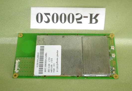
Click to zoom
Application Details
- Equipment Class
- DSS - Part 15 Spread Spectrum Transmitter
- Date of Grant
- Mar 07, 2002
- Application Purpose
- Original Equipment
- Date of Application
- Mar 07, 2002
- Equipment Note
- Wireless LAN Module
- Frequency Range
- 2412.00000000 - 2462.00000000
- Company
- Quanta Computer Inc
- Country
- Taiwan
Documents & Files
Document Text
Text extracted from the exhibit documents filed with the FCC. Open a document above to read the original.
Users Manual
11Mbps MiniUSB Wireless Adapter Date of Issue: January. 25, 2002 Technical Support The firmware version of the MiniUSB Wireless Adapter is displayed on the utility About window. Users could download the most recent software version from the supplier’s web site or refer to the selling contact for the latest software information. If you have difficulty resolving the problem while installing or using the 11Mbps MiniUSB Wireless Adapter, please contact the supplier for support. About This Manual 11Mbps MiniUSB Wireless Adapter User Manual is first published on January, 2002. The manual includes procedures for the setup of the 11Mbps MiniUSB Wireless Adapter under Windows XP, Windows 2000, Windows 98 or Windows ME. Take a moment to read through this manual and familiarize yourself with wireless technology. FCC Information This device complies with Part 15 of the FCC Rules. Operation is subject to the following two conditions: (1) this device may not cause harmful interference, and (2) this device must accept any interference received; including interference that may cause undesired operation. Federal Communications Commission (FCC) Statement This Equipment has been tested and found to comply with the limits for a Class B digital device, pursuant to Part 15 of the FCC rules. These limits are designed to provide reasonable protection against harmful interference in a residential installation. This equipment generates, uses and can radiate radio frequency energy and, if not installed and used in accordance with the instructions, may cause harmful interference to radio communications. However, there is no guarantee that interference will not occur in a particular installation. If this equipment does cause harmful interference to radio or television reception, which can be determined by turning the equipment off and on, the user is encouraged to try to correct the interference by one or more of the following measures: - Reorient or relocate the receiving antenna. - Increase the separation between the equipment and receiver. - Connect the equipment into an outlet on a circuit different from that to which the receiver is connected. - Consult the dealer or an experienced radio/TV technician for help. FCC RF Radiation Exposure Statement: 1. This Transmitter must not be co-located or operating in conjunction with any other antenna or transmitter. 2. This equipment complies with FCC RF radiation exposure limits set forth for an uncontrolled environment. This equipment should be installed and operated with a minimum distance of 20 centimeters between the radiator and your body. Limited Warranty This Warranty constitutes the sole and exclusive remedy of any buyer or reseller’s equipment and the sole and exclusive liability of the supplier in connection with the products and is in lieu of all other warranties, express, implied or statutory, including, but not limited to, any implied warranty of merchantability of fitness for a particular use and all other obligations or liabilities of the supplier. In no even will the supplier or any other party or person be liable to your or anyone else for any damages, including lost profits, lost savings or other incidental or consequential damages, or inability to use the software provided on the software media even if the supplier or the other party person has been advised of the possibility of such damages. The following are special terms applicable to your hardware warranty as well as services you may use during part of the warranty period. Your formal Warranty Statement, including the warranty applicable to our Wireless LAN products, appears in the Quick Installation Guide, which accompanies your products. Duration of Hardware Warranty: One Year Replacement, Repair or Refund Procedure for Hardware: If your unit needs a repair or replacement, return it to your dealer/distributor in its original packaging. When returning a defective product for Warranty, always include the following documents: n The Warranty Repair Card n A copy of the invoice/proof of purchase, and n The RMA Report Form (To receive a Return Materials Authorization form (RMA), please contact the party from whom you purchased the product). Upon proof-of-purchase we shall, at its option, repair or replace the defective item at no cost to the buyer. This warranty is contingent upon proper use in the application for which the products are intended and does not cover products which have been modified without the reseller’s approval or which have been subjected to unusual physical or electrical demands or damaged in any way. Please complete the information below and include it along with your products. Name: Title: Company: Telephone: Fax: Email: City/State/Zipcode: Country: Product Name: Serial Number: MAC Address: Invoice Date: Product Description: If you have any further questions, please contact your local authorized reseller for support. Table of Contents FCC Information ...........................................................................................2 Limited Warranty ..........................................................................................3 Chapter 1 About MiniUSB Wireless Adapter...........................................1 1-1 Features and Benefits............................................................................1 1-2 Applications..........................................................................................2 1-3 Product Kit...........................................................................................3 Chapter 2 Getting Started...........................................................................4 2-1 Before Installation.................................................................................4 Chapter 3 Install Driver for Windows........................................................5 3-1 Set up MiniUSB Wireless Adapter for Windows XP...............................5 3-2 Set up MiniUSB Wireless Adapter for Windows 2000.......…
Text truncated - open the document above for the full version.
Cover Letter(s)
C&C Laboratory Co. Ltd. REPORT NO: 020005-R FCC ID: HFSEFSERIES DATE: 03/08/2002 Accredited Lab. of NEMKO, A2LA, BSMI, CNLA NEMKO Authorization #: ELA 124 Page 90 Listed Lab. of FCC, VCCI, MOC A2LA Certificate #: 824.01 (for Emission) This report shall not be reproduced except in full, without the written approval of C&C Rev. 02 APPENDIX 9 RF Exposure Warning Language in User Manual
Cover Letter(s)
From: Nancy [[email protected]] Sent: Friday, February 22, 2002 3:57 AM To: Mike Kuo Cc: ??? Subject: Answers for FCC ID: HFSEFSERIES / Assessment No.: AN02T1790 Dear Mike, I am glad to received the message from you, Thank you for your advice. With regarding to Quanta issue FCC ID: HFSEFSERIES, Assessment No.: AN02T1790, the questions' answers as below: Question #1: Please see attachment file: XI726 circuit description-Q1 Question #2: Please see attachment file: XI726 circuit description Question #3: Please see attachment file: FCC LA-System & FCC-LA-Module Question #4: Regarding Page 4 of test report listed the frequency range is from 2400-2470MHz that are available chip for module , but this USB Wireless LAN Module is fixed from 2412-2462MHz. So, please see page 4 of test report listed that have been modify it. ( Please see attachment file: Page 4 of test report) Question #5: Please see attachment file: 15.205 1000-4824MHz data Question #6: Please see attachment file: 15.206(15.109) Test Requirement Question #7: Please see attachment file: Output Power spectrum plot Question #8: Please see attachment file: 30MHz to 10 th Harmonics spectrum plots. Question #9: Regarding MPE calculation equation formal is safe distance (cm). Distance (cm) = 100*(30/(3770*1.0)) /\ 0.5*(10 /\ (115dBm-30+2.14dBi)/20) = 2.03cm ≒ 2.5cm So, addition caution in the Page 30 of user manual . But written "FCC RF Radiation Exposure statement : "2. This equipment complies with FCC RF radiation exposure limits set forth for an uncontrolled environment. This equipment should be installed and operated with a minimum distance of 20 centimeters between the radiator and your body." and according to 2.1093(b), this equipment MPE calculation to comply with 15.247(b)(4). Question #10: Please see attachment file: Antenna Requirement Question #11: Please see attachment file: Athu. Letter If you have any other requests please let me know. Thanks a lot for your advice. Best regards, Nancy Tel: +886-3-324-5966#25 6. “The modular transmitter must be labeled with its own FCC ID number.” The EUT is labeled with its own FCC ID number. Please see APPENDIX 5 for a drawing of the label and its location on the device, since the FCC ID number will not be visible when the module is installed inside a host computer, there is instructions given to the OEM on how to apply the exterior label, please see page 2 of APPENDIX 5. 7. “The modular transmitter must comply with any specific rule or operating requirements and the manufacture must provide adequate instruction along with the module to explain any such requirements.” The EUT is compliant with all applicable FCC rules, Detail instructions RF Exposure. Please see the Test Report. Question 13: In my previous question #6. I am not asking for the instrument used ( test equipment list ). I need to know the RBW used for 15.109/15.209 measurement. Please provide it. Please see note of page 15 of the Test Report. Question 14: In my previous question #6. I am not asking for the instrument used ( test equipment list ). I need to know the RBW used for 15.109/15.209 measurement. Please provide it. Pplease see graph of page 30, 31, 32 of the Test Report. Question 15: In my previous question #11. I request to have cover letter to indicate which documents ( schematic diagram, block diagram etcc.) will be withheld from public disclosure. You provide a agency authorization letter. Authorization letter can not be used for requesting for confidentiality letter. Please see APPENDIX 6. Question 16: Please provide a revised user manual to include the RF exposure information indicated in your e-mail. Please see APPENDIX 7.
Cover Letter(s)
March 08, 2002 The 2.4 GHz Direct sequence spread spectrum USB wireless LAN Module, FCC ID, HFSEFSERIES is seeking FCC Authorization as a modular transmitter. The EUT meets the requirements for modular approval as detailed in FCC public Notice DA00-1407. Compliance to each of the requirements is described bellow: Question is 1. “The modular transmitter must have its own RF shielding.” The radio portion of the wireless LAN Module has its own RF shieldings. The shieldings are installed at the factory. Please see page 1 of Appendix 1 for photographs of the shielding. 2. “The modular transmitter must have buffered modulation / data inputs.” The EUT has buffered data inputs to insure compliance with part 15 requirements under condition of excessive data rates or over – modulation. Please see Appendix 2 for schematics of the module and Appendix 3. 3. “The modular transmitter must have its own power supply regulation” The EUT uses USB host power. It insures compliance with port 15 supplying the module from the host unit. Please see APPENDIX 2 for schematics of the module and Appendix 3. 4. “The modular transmitter must comply with the antenna requirements of section 15.203 and 15.204 (c)” The EUT meets the FCC antenna requirements. Please see APPENDIX 3 for x1726 circuit Description, APPENDIX 1 for photographs of the Antennas, APPENDIX 4 for Antenna Connection method. 5. “The modular transmitter must be tested in a stand – alone configuration.” The EUT was tested in a stand – alone configuration. Please see APPENDIX 3 for x1726 circuit Description, and test report for the testing setup photos. Please see note of Description that the EUT. 6. “The modular transmitter must be labeled with its own FCC ID number.” The EUT is labeled with its own FCC ID number. Please see APPENDIX 5 for a drawing of the label and its location on the device, since the FCC ID number will not be visible when the module is installed inside a host computer, there is instructions given to the OEM on how to apply the exterior label, please see page 2 of APPENDIX 5. 7. “The modular transmitter must comply with any specific rule or operating requirements and the manufacture must provide adequate instruction along with the module to explain any such requirements.” The EUT is compliant with all applicable FCC rules, Detail instructions RF Exposure. Please see the Test Report. Question 13: In my previous question #6. I am not asking for the instrument used ( test equipment list ). I need to know the RBW used for 15.109/15.209 measurement. Please provide it. Please see note of page 15 of the Test Report. Question 14: In my previous question #6. I am not asking for the instrument used ( test equipment list ). I need to know the RBW used for 15.109/15.209 measurement. Please provide it. Pplease see graph of page 30, 31, 32 of the Test Report. Question 15: In my previous question #11. I request to have cover letter to indicate which documents ( schematic diagram, block diagram etcc.) will be withheld from public disclosure. You provide a agency authorization letter. Authorization letter can not be used for requesting for confidentiality letter. Please see APPENDIX 6. Question 16: Please provide a revised user manual to include the RF exposure information indicated in your e-mail. Please see APPENDIX 7.
Cover Letter(s)
C&C Laboratory Co. Ltd. REPORT NO: 020005-R FCC ID: HFSEFSERIES DATE: 03/08/2002 Accredited Lab. of NEMKO, A2LA, BSMI, CNLA NEMKO Authorization #: ELA 124 Page 76 Listed Lab. of FCC, VCCI, MOC A2LA Certificate #: 824.01 (for Emission) This report shall not be reproduced except in full, without the written approval of C&C Rev. 02 APPENDIX 4 ANTENNA PROCEDURE C&C Laboratory Co. Ltd. REPORT NO: 020005-R FCC ID: HFSEFSERIES DATE: 03/08/2002 Accredited Lab. of NEMKO, A2LA, BSMI, CNLA NEMKO Authorization #: ELA 124 Page 77 Listed Lab. of FCC, VCCI, MOC A2LA Certificate #: 824.01 (for Emission) This report shall not be reproduced except in full, without the written approval of C&C Rev. 02 C&C Laboratory Co. Ltd. REPORT NO: 020005-R FCC ID: HFSEFSERIES DATE: 03/08/2002 Accredited Lab. of NEMKO, A2LA, BSMI, CNLA NEMKO Authorization #: ELA 124 Page 78 Listed Lab. of FCC, VCCI, MOC A2LA Certificate #: 824.01 (for Emission) This report shall not be reproduced except in full, without the written approval of C&C Rev. 02 C&C Laboratory Co. Ltd. REPORT NO: 020005-R FCC ID: HFSEFSERIES DATE: 03/08/2002 Accredited Lab. of NEMKO, A2LA, BSMI, CNLA NEMKO Authorization #: ELA 124 Page 79 Listed Lab. of FCC, VCCI, MOC A2LA Certificate #: 824.01 (for Emission) This report shall not be reproduced except in full, without the written approval of C&C Rev. 02 C&C Laboratory Co. Ltd. REPORT NO: 020005-R FCC ID: HFSEFSERIES DATE: 03/08/2002 Accredited Lab. of NEMKO, A2LA, BSMI, CNLA NEMKO Authorization #: ELA 124 Page 80 Listed Lab. of FCC, VCCI, MOC A2LA Certificate #: 824.01 (for Emission) This report shall not be reproduced except in full, without the written approval of C&C Rev. 02 C&C Laboratory Co. Ltd. REPORT NO: 020005-R FCC ID: HFSEFSERIES DATE: 03/08/2002 Accredited Lab. of NEMKO, A2LA, BSMI, CNLA NEMKO Authorization #: ELA 124 Page 81 Listed Lab. of FCC, VCCI, MOC A2LA Certificate #: 824.01 (for Emission) This report shall not be reproduced except in full, without the written approval of C&C Rev. 02 C&C Laboratory Co. Ltd. REPORT NO: 020005-R FCC ID: HFSEFSERIES DATE: 03/08/2002 Accredited Lab. of NEMKO, A2LA, BSMI, CNLA NEMKO Authorization #: ELA 124 Page 82 Listed Lab. of FCC, VCCI, MOC A2LA Certificate #: 824.01 (for Emission) This report shall not be reproduced except in full, without the written approval of C&C Rev. 02 C&C Laboratory Co. Ltd. REPORT NO: 020005-R FCC ID: HFSEFSERIES DATE: 03/08/2002 Accredited Lab. of NEMKO, A2LA, BSMI, CNLA NEMKO Authorization #: ELA 124 Page 83 Listed Lab. of FCC, VCCI, MOC A2LA Certificate #: 824.01 (for Emission) This report shall not be reproduced except in full, without the written approval of C&C Rev. 02 C&C Laboratory Co. Ltd. REPORT NO: 020005-R FCC ID: HFSEFSERIES DATE: 03/08/2002 Accredited Lab. of NEMKO, A2LA, BSMI, CNLA NEMKO Authorization #: ELA 124 Page 84 Listed Lab. of FCC, VCCI, MOC A2LA Certificate #: 824.01 (for Emission) This report shall not be reproduced except in full, without the written approval of C&C Rev. 02 C&C Laboratory Co. Ltd. REPORT NO: 020005-R FCC ID: HFSEFSERIES DATE: 03/08/2002 Accredited Lab. of NEMKO, A2LA, BSMI, CNLA NEMKO Authorization #: ELA 124 Page 85 Listed Lab. of FCC, VCCI, MOC A2LA Certificate #: 824.01 (for Emission) This report shall not be reproduced except in full, without the written approval of C&C Rev. 02
External Photos
C&C Laboratory Co. Ltd. REPORT NO: 020005-R FCC ID: HFSEFSERIES DATE: 01/28/2002 Accredited Lab. of NEMKO, A2LA, BSMI, CNLA NEMKO Authorization #: ELA 124 Page 48 Listed Lab. of FCC, VCCI, MOC A2LA Certificate #: 824.01 (for Emission) This report shall not be reproduced except in full, without the written approval of C&C Rev. 02 Photo of EUT
ID Label/Location Info
C&C Laboratory Co. Ltd. REPORT NO: 020005-R FCC ID: HFSEFSERIES DATE: 03/08/2002 Accredited Lab. of NEMKO, A2LA, BSMI, CNLA NEMKO Authorization #: ELA 124 Page 86 Listed Lab. of FCC, VCCI, MOC A2LA Certificate #: 824.01 (for Emission) This report shall not be reproduced except in full, without the written approval of C&C Rev. 02 APPENDIX 5 Proposed FCC ID Label Format C&C Laboratory Co. Ltd. REPORT NO: 020005-R FCC ID: HFSEFSERIES DATE: 03/08/2002 Accredited Lab. of NEMKO, A2LA, BSMI, CNLA NEMKO Authorization #: ELA 124 Page 87 Listed Lab. of FCC, VCCI, MOC A2LA Certificate #: 824.01 (for Emission) This report shall not be reproduced except in full, without the written approval of C&C Rev. 02 C&C Laboratory Co. Ltd. REPORT NO: 020005-R FCC ID: HFSEFSERIES DATE: 03/08/2002 Accredited Lab. of NEMKO, A2LA, BSMI, CNLA NEMKO Authorization #: ELA 124 Page 88 Listed Lab. of FCC, VCCI, MOC A2LA Certificate #: 824.01 (for Emission) This report shall not be reproduced except in full, without the written approval of C&C Rev. 02
Internal Photos
C&C Laboratory Co. Ltd. REPORT NO: 020005-R FCC ID: HFSEFSERIES DATE: 01/28/2002 Accredited Lab. of NEMKO, A2LA, BSMI, CNLA NEMKO Authorization #: ELA 124 Page 49 Listed Lab. of FCC, VCCI, MOC A2LA Certificate #: 824.01 (for Emission) This report shall not be reproduced except in full, without the written approval of C&C Rev. 02
Internal Photos
C&C Laboratory Co. Ltd. REPORT NO: 020005-R FCC ID: HFSEFSERIES DATE: 03/08/2002 Accredited Lab. of NEMKO, A2LA, BSMI, CNLA NEMKO Authorization #: ELA 124 Page 68 Listed Lab. of FCC, VCCI, MOC A2LA Certificate #: 824.01 (for Emission) This report shall not be reproduced except in full, without the written approval of C&C Rev. 02
Operational Description
ZCOM, Inc. 7F-2, 9, Prosperity 1st Rd., Science-Based Industrial Park, Hsinchu, Taiwan Website: http:/// www.zcom.com.tw Tel: +886-3-577-7364 Fax: +886-3-577-3359 Page 1 of 5 XI726 Circuit Description ZCOM/Gilbert Tsai ZCOM, Inc. 7F-2, 9, Prosperity 1st Rd., Science-Based Industrial Park, Hsinchu, Taiwan Website: http:/// www.zcom.com.tw Tel: +886-3-577-7364 Fax: +886-3-577-3359 Page 2 of 5 Block Diagram Key Component Description MAC & BBP ISL3873B: U3 ISL3873B has both MAC (Media Access Controller) and BBP (Base Band Processor), it directly interfaces with the IF Qmodem (U8 HFA3783) and USB v1.1 interface. Adding RF/IF Converter (ISL3685) and Power amplifier (ISL3984) to offer the complete WLAN solution. IEEE802.11 Protocol and PHY support are implemented in firmware thus, supporting customization of the WLAN solution. The ISL3873B has on board A/Ds and D/A for analog I and Q inputs and outputs, for which the HFA3783 recommended. DBPSK and DQPSK with data scrambling capability, are available along with CCK to provide a variety of data rates. Both Receive and Transmit AGC functions with 7-bit AGC control obtain maximum performance in the analog portion of the transceiver. IF QMODEM HFA3783: HFA3783 is a highly integrated and fully SiGe baseband converter for half duplex wireless application. It has integrated AGC receive IF amplifier and variety Transmit amplifier. Receive and Transmit paths share a common differential path. A pair of 2 nd order anti-aliasing filters with an integrated DC offset cancellation architecture is included in the AGC chain for threshold comparison. Up and down conversion are performed by doubly balanced mixer for I/Q IF processing. RF/IF Converter and Synthesizer ISL3685: ZCOM, Inc. 7F-2, 9, Prosperity 1st Rd., Science-Based Industrial Park, Hsinchu, Taiwan Website: http:/// www.zcom.com.tw Tel: +886-3-577-7364 Fax: +886-3-577-3359 Page 3 of 5 U14 ISL3685 includes a receive chain feature LNA and down-converter mixer. TX chain has an up-converter mixer and driver amplifier. RF synthesizer can phase lock the VCO at 2.1GHz and converts 374MHz IF and 2.4GHz RF through 2.1GHz LO. RF Power Amplifier ISL3984: The U16 ISL3984 is a 2.4GHz RF power amplifier that amplifies the signal from ISL3685 transmit chain. ISL3984 includes both power amplifier and power detector that can perform ALC (Automatic Level Control) function. RF Filter FL4 MDR742F and FL2 MDR741F: Pass the desired RF signal and reject spurious from transmit-chain mixer that ISL3685 polling out. Transmit/Receive Switch U11 NJG1533KB2: Control RF signal to Receive or transmit path by ISL3873B. Antenna Switch U13 AS179-92: Antenna controlled by ISL3873B, and can be configured by register setting ZCOM, Inc. 7F-2, 9, Prosperity 1st Rd., Science-Based Industrial Park, Hsinchu, Taiwan Website: http:/// www.zcom.com.tw Tel: +886-3-577-7364 Fax: +886-3-577-3359 Page 4 of 5 RX Signal Flow 1. The signal is received by one of two antennas through ANT Switch 2. Signal passes to one BPF for image rejection, and then feeds to LNA for front-end signal amplification and raise the SNR 3. Down-convert the frequency from RF to IF in ISL3685 4. After ISL3685, SAW filter rejects image spurious with its sharp shape 5. HFA3783 can dynamic adjust variable 70dB gain according to receiving signal variation, and down-convert to baseband I/Q balanced signal 6. ISL3873 demodulates the data from I/Q signals to packet-form information, and passes the data to host via USB interface ZCOM, Inc. 7F-2, 9, Prosperity 1st Rd., Science-Based Industrial Park, Hsinchu, Taiwan Website: http:/// www.zcom.com.tw Tel: +886-3-577-7364 Fax: +886-3-577-3359 Page 5 of 5 Transmit Signal Flow 1. ISL3873B receives the data from host via USB interface. Also, packetizes to compliant with 802.11b and translates into BPSK, QPSK and CCK I/Q signal by different rate – 1, 2, 5.5 and 11Mbps 2. Up-convert the I/Q to IF 374MHz and a variable gain block amplifies the IF signal by TX close-loop control 3. Filtering the signal by SAW filter to reject the spurious 4. Channel can be settled by changing PLL lock frequency via 3-wire control. Then IF signal can be up-convert to RF in ISL3685 5. The unwanted signal is filtered out by a BPF and feeds into PA 6. After the power amplified, a BPF rejects the harmonics and spurious 7. One of two antennas is chose for diversity
RF Exposure Info
From: Nancy [[email protected]] Sent: Friday, February 22, 2002 3:57 AM To: Mike Kuo Cc: ??? Subject: Answers for FCC ID: HFSEFSERIES / Assessment No.: AN02T1790 Dear Mike, I am glad to received the message from you, Thank you for your advice. With regarding to Quanta issue FCC ID: HFSEFSERIES, Assessment No.: AN02T1790, the questions' answers as below: Question #1: Please see attachment file: XI726 circuit description-Q1 Question #2: Please see attachment file: XI726 circuit description Question #3: Please see attachment file: FCC LA-System & FCC-LA-Module Question #4: Regarding Page 4 of test report listed the frequency range is from 2400-2470MHz that are available chip for module , but this USB Wireless LAN Module is fixed from 2412-2462MHz. So, please see page 4 of test report listed that have been modify it. ( Please see attachment file: Page 4 of test report) Question #5: Please see attachment file: 15.205 1000-4824MHz data Question #6: Please see attachment file: 15.206(15.109) Test Requirement Question #7: Please see attachment file: Output Power spectrum plot Question #8: Please see attachment file: 30MHz to 10 th Harmonics spectrum plots. Question #9: Regarding MPE calculation equation formal is safe distance (cm). Distance (cm) = 100*(30/(3770*1.0)) /\ 0.5*(10 /\ (115dBm-30+2.14dBi)/20) = 2.03cm ≒ 2.5cm So, addition caution in the Page 30 of user manual . But written "FCC RF Radiation Exposure statement : "2. This equipment complies with FCC RF radiation exposure limits set forth for an uncontrolled environment. This equipment should be installed and operated with a minimum distance of 20 centimeters between the radiator and your body." and according to 2.1093(b), this equipment MPE calculation to comply with 15.247(b)(4). Question #10: Please see attachment file: Antenna Requirement Question #11: Please see attachment file: Athu. Letter If you have any other requests please let me know. Thanks a lot for your advice. Best regards, Nancy Tel: +886-3-324-5966#25
RF Exposure Info
C&C Laboratory Co. Ltd. REPORT NO: 020005-R FCC ID: HFSEFSERIES DATE: 03/08/2002 Accredited Lab. of NEMKO, A2LA, BSMI, CNLA NEMKO Authorization #: ELA 124 Page 92 Listed Lab. of FCC, VCCI, MOC A2LA Certificate #: 824.01 (for Emission) This report shall not be reproduced except in full, without the written approval of C&C Rev. 02
Test Report
C&C Laboratory Co. Ltd. REPORT NO: 020005-R FCC ID: HFSEFSERIES DATE: 02/18/2002 Accredited Lab. of NEMKO, A2LA, BSMI, CNLA NEMKO Authorization #: ELA 124 Page 1 of 69 Listed Lab. of FCC, VCCI, MOC A2LA Certificate #: 824.01 (for Emission) This report shall not be reproduced except in full, without the written approval of C&C Rev. 02 ELECTROMAGNETIC EMISSIONS COMPLIANCE REPORT INTENTIONAL RADIATOR CERTIFICATION TO FCC PART 15 SUBPART C REQUIREMENT OF 2.4GHz Direct Sequence Spread Spectrum USB Wireless LAN Module MODEL No.: XI726 mini USB module BRAND NAME: Quanta FCC ID: HFSEFSERIES REPORT NO: 020005-R ISSUE DATE: March 8, 2002 Prepared for Quanta Computer Inc. No. 188, Wen Hwa 2 nd Rd., Kuei shan Hsiang, Tao Yuan Shien, Taiwan, R. O. C. Prepared by C&C LABORATORY, CO., LTD. #B1, 1 st Fl., Universal Center, No. 183, Sec. 1, Tatung Rd., Hsi Chih, Taipei Hsien, Taiwan, R.O.C. TEL: (02)8642-2071~3 FAX: (02)8642-2256 C&C Laboratory Co. Ltd. REPORT NO: 020005-R FCC ID: HFSEFSERIES DATE: 03/08/2002 Accredited Lab. of NEMKO, A2LA, BSMI, CNLA NEMKO Authorization #: ELA 124 Page 2 Listed Lab. of FCC, VCCI, MOC A2LA Certificate #: 824.01 (for Emission) This report shall not be reproduced except in full, without the written approval of C&C Rev. 02 TABLE OF CONTENT PAGE 1. VERIFICATION OF COMPLIANCE.................................................................................3 2. DESCRIPTION OF EQUIPMENT UNDER TEST (EUT).................................................4 3. TEST LOCATION.................................................................................................................4 4. DESCRIPTION OF TEST MODES..................................................................................................5 5. SUPPORT EQUIPMENT......................................................................................................5 6. TEST PROCEDURES AND TEST RESULTS....................................................................6 RADIATED EMISSIONS (GENERAL REQUIREMENTS).....................................................................6 TEST REQUIREMENT: 15.205.......................................................................................................6 TEST REQUIREMENT: 15.209 (15.109).......................................................................................14 TEST REQUIREMENT: 15.207.....................................................................................................19 MINIMUM 6 DB BANDWIDTH FOR DSSS...................................................................................23 TEST REQUIREMENT: 15.247(A)(2)............................................................................................23 RF POWER OUTPUT...................................................................................................................28 TEST REQUIREMENT: 15.247(B).................................................................................................28 OUT OF BAND MEASUREMENTS.................................................................................................33 TEST REQUIREMENT: 15.247(C).................................................................................................33 DSSS POWER DENSITY.............................................................................................................55 TEST REQUIREMENT: 15.247(D).................................................................................................55 PROCESSING GAIN OF A DSSS..........................................................................64 TEST REQUIREMENT: 15.247(E)........................................................................64 APPENDIX 1 EUT PHOTOGRAPHS APPENDIX 2 MANUAL / SCHEMATICS / BLOCK DIAGRAM APPENDIX 3 CIRCUIT DESCRIPTION APPENDIX 4 ANTENNA PROCEDURE APPENDIX 5 PROPOSED FCC ID LABEL FORMAT APPENDIX 6 CONFIDENTIAL STATUS APPENDIX 7 RF EXPOSURE WARNING LANGUAGE IN USER MANUAL C&C Laboratory Co. Ltd. REPORT NO: 020005-R FCC ID: HFSEFSERIES DATE: 03/08/2002 Accredited Lab. of NEMKO, A2LA, BSMI, CNLA NEMKO Authorization #: ELA 124 Page 3 Listed Lab. of FCC, VCCI, MOC A2LA Certificate #: 824.01 (for Emission) This report shall not be reproduced except in full, without the written approval of C&C Rev. 02 1. VERIFICATION OF COMPLIANCE COMOANY NAME: Quanta Computer Inc. CONTACT PERSON: Joyce Kuo / R & D Dept. 5 Design Section 3 EMI Specialist TELEPHONE NO.: +886-3-3272345 # 5714 EUT DESCRIPTION: 2.4GHz Direct Sequence Spre…
Text truncated - open the document above for the full version.
Contact Information
Applicant
Joyce Kuo
Test Firm
Compliance Certification Services Inc.Kurt Chen
Technical Specifications
| # | Rule Parts | Frequency Range | Power Output |
|---|---|---|---|
| 1 | 15C | 2.41 GHz - 2.46 GHz | 33.00 mW |
Other Applications from Quanta Computer Inc
HFS-QV28NRW
Jul 15, 2026Telematics Module
Equipment Class
PCB - PCS Licensed TransmitterHFSCIP
Jun 15, 2026QOCA ecg1202
Equipment Class
DTS - Digital Transmission System
HFS-QV28NUS
Apr 16, 2026Telematics Module
Equipment Class
PCB - PCS Licensed TransmitterHFS-C407
Jul 21, 2024Clover Flex Pocket
Equipment Class
NII - Unlicensed National Information Infrastructure TXHFS-C406
Jul 01, 2024Clover Flex
Equipment Class
DTS - Digital Transmission System