HFSWM3B2100Wireless Mini PCI LAN Module
Quanta Computer Inc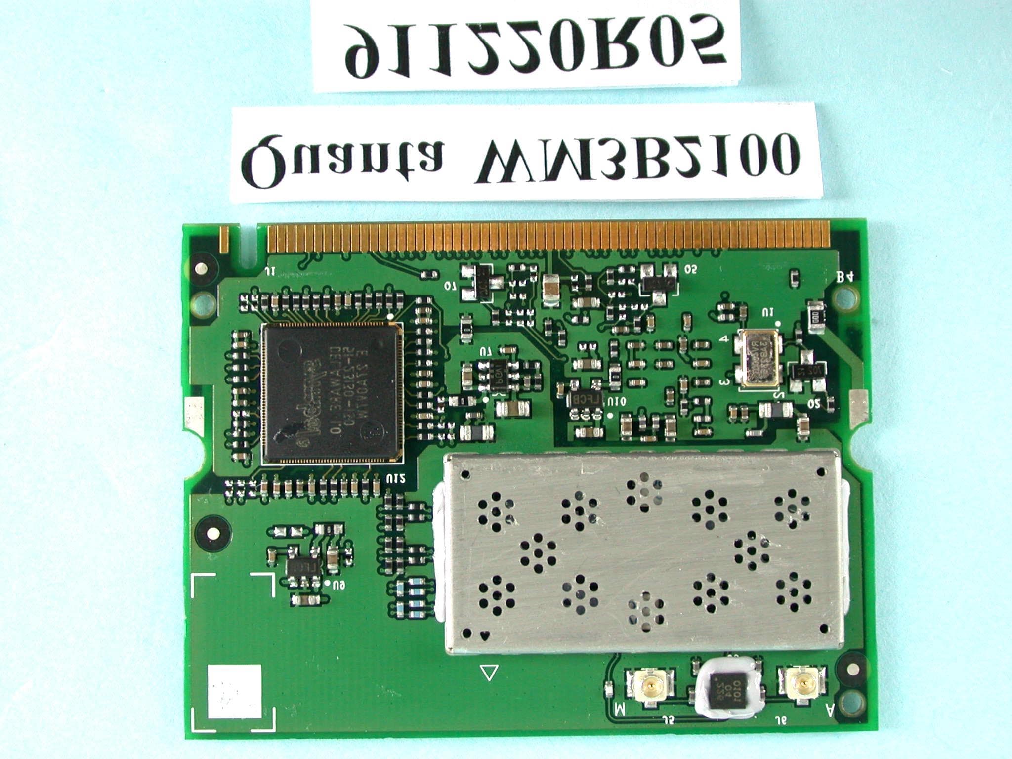
Click to zoom
Application Details
- Equipment Class
- DTS - Digital Transmission System
- Date of Grant
- Jan 13, 2003
- Application Purpose
- Original Equipment
- Date of Application
- Jan 13, 2003
- Equipment Note
- Wireless Mini PCI LAN Module
- Frequency Range
- 2412.00000000 - 2462.00000000
- Company
- Quanta Computer Inc
- Country
- Taiwan
Documents & Files
Document Text
Text extracted from the exhibit documents filed with the FCC. Open a document above to read the original.
Users Manual
Intel(R) PRO/Wireless LAN Mini PCI Adapter User's Guide [Preliminary Draft] The Intel(R) PRO/Wireless LAN Mini PCI Adapter is a wireless device that operates at 5 and 2.4 GHz. This adapter operates with high-capacity networks using multiple access points within large or small environments. Using the Intel(R) PROSet Windows utility you can configure, manage wireless local area network (WLAN) management tasks, adapter switching functions, and connections. Wireless LAN General Information About Wireless LAN Technology Adapter Setup and Configuration Software Installation Using PROSet Connecting to a Network Security Overview Setting Up Security Troubleshooting Specifications Glossary Support and Warranty Customer Support Software License Safety and Regulatory Notices Limited Warranty Legal Notices Copyright © 2002 Intel Corporation. All rights reserved. Intel Corporation, 5200 N.E. Elam Young Parkway, Hillsboro, OR 97124-6497 Intel Corporation assumes no responsibility for errors or omissions in this document. Nor does Intel make any commitment to update the information contained herein. Intel, Itanium, and Pentium are trademarks or registered trademarks of Intel Corporation or its subsidiaries in the United States and other countries. *Other names and brands may be claimed as the property of others. Back to Contents About Wireless LAN Technology • Choosing a WLAN • Configuring a WLAN • Identifying a WLAN • Surveying the Site of Your WLAN • Factors Affecting Range • Stronger Security A wireless network connects computers without using network cables. Computers use radio communications to send data between each other. You can communicate directly with other wireless computers, or connect to an existing network through a wireless access point. When you set up your wireless adapter, you select the operating mode for the kind of wireless network you want. You can use your Intel(R) PRO/Wireless adapter to connect to other similar wireless devices that comply with the 802.11 standard for wireless networking. Choosing a Wireless LAN Mode Wireless LANs can operate with or without access points, depending on the number of users in the network. Infrastructure mode uses access points to allow wireless computers to send and receive information. Wireless computers transmit to the access point, the access point receives the information and rebroadcasts it to other computers. The access point can also connect to a wired network or to the Internet. Multiple access points can work together to provide coverage over a wide area. Peer-to-Peer mode, also called Ad Hoc mode, works without access points and allows wireless computers to send information directly to other wireless computers. You can use Peer-to-Peer mode to network computers in a home or small office or to set up a temporary wireless network for a meeting. Configuring a Wireless LAN There are three basic components that must be configured for a wireless LAN to operate properly: • Network Name—Each wireless network uses a unique Network Name to identify the network. This name is called the Service Set Identifier (SSID). When you set up your wireless adapter, you specify the SSID. If you want to connect to an existing network, you must use the name for that network. If you are setting up your own network you can make up your own name and use it on each computer. The name can be up to 32 characters long and contain letters and numbers. • Profiles—When you set up your computer to access a wireless network, Intel(R) PROSet creates a profile for the wireless settings that you specify. If you want to connect to another network, you can scan for existing networks and make a temporary connection, or create a new profile for that network. After you create profiles, your computer will automatically connect when you change locations. • Security—The 802.11 wireless networks use encryption to help protect your data. Wired equivalent privacy (WEP) uses a 64-bit or 128-bit shared encryption key to scramble data. Before a computer transmits data, it scrambles the data using the secret encryption key. The receiving computer uses this same key to unscramble the data. If you are connecting to an existing network, use the encryption key provided by the administrator of the wireless network. If you are setting up your own network you can make up your own key and use it on each computer. Identifying a Wireless Network Depending on the size and components of a wireless LAN, there are many ways to identify a wireless LAN: • The Network Name or Service Set Identifier (SSID)—Identifies a wireless network. All wireless devices on the network must use the same SSID. • Extended Service Set Identifier (ESSID)—A special case of SSID used to identify a wireless network that includes access points. • Independent Basic Service Set Identifier (IBSSID)—A special case of SSID used to identify a network of wireless computers configured to communicate directly with one another without using an access point. • Basic Service Set Identifier (BSSID)—A unique identifier for each wireless device. The BSSID is the Ethernet MAC address of the device. • Broadcast SSID—An access point can respond to computers sending probe packets with the broadcast SSID. If this feature is enabled on the access point, any wireless user can associate with the access point by using a blank (null) SSID. Surveying the Site of Your Wireless LAN Conducting a site survey for your wireless LAN is the most crucial step in the process of setting up a wireless network. It greatly reduces the amount of troubleshooting you will have to do once you have the wireless LAN set up and ready for connection testing. To conduct a site survey, you will need the following tools: • An access point (or laptop computer) that is set up to be the transmitter. It should be mounted near and at the same height as the designated location of your wireless LAN. • A laptop that will act as the mobile receiver. It must contain your site survey soft…
Text truncated - open the document above for the full version.
Cover Letter(s)
FCC ID: HFSWM3B2100 ADT No.911220R05 Modular Approval Request Letter Advance Data Technology Jan. 13, 2003 Dear Application Examiner, QUANTA COMPUTER INC’s Mini-PCI card, FCC ID: HFSWM3B2100, would like to have your authorization as a limited modular approval specific to the notebook with antenna mounted around the LCD panel. The requirements of Public Notice DA00-1407 have been met and shown on the following statements. 1. “The modular transmitter must have its own RF shielding.”: The radio portion of this module has been shielded, please see exhibition External Photo. 2. “The modular transmitter must have buffered modulation/data inputs.” The EUT has buffered data inputs, it is integrated in chip ARDON_A0. 3. “The modular transmitter must have its own power supply regulation.” The chips IF converter and RF/IF converter which will influence the frequency radiation, have to be 1.8V DC powered. The mini-pci interface provides 3.3VDC, so there are regulators in front of these chips, the part number of this regulator is LP2992. 4. “The modular transmitter must comply with the antenna requirements of section 15.203 and 15.204(C).” The EUT meets the FCC antenna requirements. The spurious emission, unique antenna connector and photo of antennas are shown in the test report. 5. “The modular transmitter must be tested in a stand-alone configuration” The EUT was tested in a stand-alone configuration via a PCI to mini-PCI extender. Please see section Photographs of Test Configuration in the test report, the EUT was plugged in this extender. 6. “The modular transmitter must be labeled with its own FCC ID number.” Please see exhibition Label Sample for the FCC ID of this module. And also in the exhibition Users Manual, there are instructions give to the OEM on how to label the end product. FCC ID: HFSWM3B2100 ADT No.911220R05 7. “The modular transmitter must comply with any specific rule or operating requirements applicable to the transmitter and the manufacturer must provide adequate instructions along with the module to explain any such requirements.” The EUT is compliant with all applicable FCC rules. Detail instructions for maintaining compliance are given in the Users Manual. 8. “The modular transmitter must comply with any applicable RF exposure requirements.” The EUT is compliant with all applicable RF exposure requirements. RF Exposure is addressed in the RF exposure exhibition. Please contact me if you have any further questions. Thanks for your attention. Best Regards, Dr. Alan Lane J. VP Advance Data Technology
Cover Letter(s)
American Telecommunications Certification Body Inc. 6731 Whittier Ave, McLean, VA 22101 January 14, 2003 RE: Quanta Computer Inc. FCC ID: HFSWM3B2100 After a review of the submitted information, I have a few comments on the above referenced Application. 1) The responsible party located on the DoC information sheet must be located within the U.S. Please provide a corrected copy of the DoC statement that references a U.S. based responsible party, or if this is yet to be determined, then fill in with "U.S. based responsible party yet to be determined". 2) Please provide photograph or drawing showing placement of the FCC label on the device. 3) The users manual references 802.11a and 802.11b networks, while this adapter only functions on 802.11b as given in the application. Please explain and/or modify the manual as necessary. 4) The users manual should also explain to the OEM manufacturer that the DO NOT provide any information to the end user regarding how to install or remove the device. Timothy R. Johnson Examining Engineer Direct Phone: 404-414-8071 mailto: [email protected] The items indicated above must be submitted before processing can continue on the above referenced application. Failure to provide the requested information may result in application termination. Correspondence should be considered part of the permanent submission and may be viewed from the Internet after a Grant of Equipment Authorization is issued. Please do not respond to this correspondence using the email reply button. In order for your response to be processed expeditiously, you must submit your documents through the AmericanTCB.com website. Also, please note that partial responses increase processing time and should not be submitted. Any questions about the content of this correspondence should be directed to the sender.
External Photos
Page 1 ANNEX PHOTOGRAPHS OF EUT Page 3 Page 4 Page 5 Page 6 Page 7 Page 8
ID Label/Location Info
FCC ID Label Location D D 1 2 3 4 5 6 7 ABCE 7 6 5 4 3 2 1 ECBA LTR NAME MODEL MATERIAL FINISH DATE SCALE UNIT MM DWG. NO. APPROVED DESIGNED DRAWN REV 3B TOL. + - 1 PLC2 PLCANGLE 7F, 116 HOU KANG ST. SHIN LIN, TAIPEI, TAIWAN, R.O.C. ITEMDESCRIPTION REVISIONS DESCRIPTION DATEAPP THE 3RD PROJECTION PART NO. Quanta Computer Inc. 2 1 3 FIRST RELEASE RITA S/N HCYA1004 1/1 HCYA1004011 91.11.18 91.03.29 Ya1 WIRELESS LBL(SYSTEM) SEE NOTES 3A Rita 0.1 3B SEE NOTES NOTES 3C 8 . 0 40.0 FCC ID:HFSWM3B2100 IC: 1787B-WM3B2100 IEEE 802.11B RLan Card CHANGE TEXT FROM CANADA TO IC: 91.11.18 Rita 3B D D 1 2 3 4 5 6 7 ABCE 7 6 5 4 3 2 1 ECBA LTR NAME MODEL MATERIAL FINISH DATE SCALE UNIT MM DWG. NO. APPROVED DESIGNED DRAWN REV 3A TOL. + - 1 PLC2 PLCANGLE 7F, 116 HOU KANG ST. SHIN LIN, TAIPEI, TAIWAN, R.O.C. ITEMDESCRIPTION REVISIONS DESCRIPTION DATEAPP THE 3RD PROJECTION PART NO. Quanta Computer Inc. 2 1 3 FIRST RELEASE RITA S/N HC0A2 1/1 HC0A2 91.12.23 91.12.23 Oa2 Wireless LABEL 3A Rita 0.1 3B 3 6 Fitted with Intel FCC ID: HFSWM3B2100 IC: 1787B-WM3B2100 WM3B2100 802.11B Wireless Lan Card. Contains CAUTION - Do not remove cover. User access is prohibited. Breaking this seal will void your warranty. 9003054
Internal Photos
Page 2
Operational Description
FCC ID: HFSWM3B2100 ADT No.911220R05 Operational Description The transmitter of the EUT is powered by host equipment. Four different Inverted F Antennas are provided to this EUT. The antenna connector type is UFL. This device would like to have your authorization for Limited Module Approval specific to notebook. Under normal use condition, the user has to keep at least 20cm separation distance between radiator and the body of the user. The other instruction, please have a look at the users manual. DSSS Information This device is Direct Sequence Spread Spectrum, the data is mixed by pseudorandom code which is an orthogonal code. The mixed data is digital modulated by BPSK and QPSK technique depends on the data rates. The CCK coding is applied for increasing the data rate, and also the processing gain will be increased. The bit rates are 1,2,5.5,11Mbps, the symbol rates are 1,1,1.375,1.375Mbps, the chip rates are always 11Mbps. So, the Chip/symbol is 11,11,8 and 8 respectively. Although is higher bit rate, the processing gain is lower than 10, but the CCK coding used in higher bit rate will provide 2.2dB coding gain.
RF Exposure Info
FCC ID: HFSWM3B2100 ADT No.: 911220R05 FCC TEST REPORT REPORT NO.: RF911220R05 MODEL NO.: WM3B2100 ACCORDING: FCC Guidelines for Human Exposure IEEE C95.1 APPLICANT:QUANTA COMPUTER INC. ADDRESS: 7F, No.116, Hou Kang St., Shih Lin 111, Taipei, Taiwan, R.O.C. ISSUED BY:Advance Data Technology Corporation LAB LOCATION:47 14th Lin, Chiapau Tsun, Linko, Taipei, Taiwan, R.O.C. 0528 ILAC MRA Lab Code: 200102-0 FCC ID: HFSWM3B2100 ADT No.: 911220R05 RF Exposure Measurement (Mobile Device) 1. Introduction 2.4 GHz frequency band is regarded specially as a dangerous band for its heating harmfulness to the human body. That’s why microwave oven is operating in this frequency band. The manufacturer whose product is working in this frequency band is obligatory to prove the harmfulness of his product. In this document, we try to prove the safety of radiation harmfulness to the human body for our product. The limit for Maximum Permissible Exposure (MPE) specified in FCC 1.1310 is followed. The Gain of the antenna used in this product is measured in a Fully Anechoic Chamber (FAC), and the maximum total power input to the antenna is measured. Through the Friis transmission formula and the maximum gain of the antenna, we can calculate the distance, away from the product, where the limit of MPE is reached. 2. Classification The antenna of the product, under normal use condition, is at least 20 cm away from the body of the user. Warning statement for keeping 20 cm separation distance and the prohibition of operating next to a person has been printed on the users manual. So, this product is classified as the Mobile Device. 3. RF Exposure Limit According to FCC 1.1310: The criteria listed in the following table shall be used to evaluate the environmental impact of human exposure to radio-frequency (RF) radiation as specified in 1.1307(b). FCC ID: HFSWM3B2100 ADT No.: 911220R05 LIMITS FOR MAXIMUM PERMISSIBLE EXPOSURE (MPE) Frequency Range (MHz) Electric Field Strength (V/m) Magnetic Field Strength (A/m) Power Density (mW/cm 2 ) Average Time (minutes) (A)Limits For Occupational / Control Exposures 30-30061.40.1631.06 300-1500......F/3006 1500-100,000......56 (B)Limits For General Population / Uncontrolled Exposure 30-30027.50.0730.230 300-1500......F/150030 1500-100,000......1.030 F = Frequency in MHz 4. Friis Formula Friis transmission formula : Pd = (Pout*G) / (4*pi*r 2 ) where Pd = power density in mW/cm 2 Pout = output power to antenna in mW G = gain of antenna in linear scale Pi = 3.1416 R = distance between observation point and center of the radiator in cm Pd is the limit of MPE, 1 mW/cm 2 . If we know the maximum Gain of the antenna and the total power input to the antenna, through the calculation, we will know the distance r where the MPE limit is reached. Ref. : David K. Cheng, Field and Wave Electromagnetics, Second Edition, Page 640, Eq. (11-133). 5. EUT Operating condition The software provided by Manufacturer enabled the EUT to transmit and receive data at lowest, middle and highest channel individually. FCC ID: HFSWM3B2100 ADT No.: 911220R05 6. Test Results 6.1 Antenna Gain The maximum Gain measured in Fully Anechoic Chamber is 1.26dBi or 1.34(numeric). 6.2 Output Power Into Antenna & RF Exposure Distance : CHANNEL CHANNEL FREQUENCY (MHz) OUTPUT POWER TO ANTENNA (mW) MINIMUM ALLOWABLE DISTANCE ( r ) FROM SKIN (Centi-Meter) 1241248.0842.261 6243747.2062.243 11246238.3702.023 The minimum allowable distance is very close to the enclosure of the antenna and is very far away from the human being under normal use condition.
Test Report
FCC ID: HFSWM3B2100 Report No.: RF911220R05 1 Issued: Jan. 10, 2003 FCC TEST REPORT REPORT NO.: RF911220R05 MODEL NO.: WM3B2100 RECEIVED: Dec. 20, 2002 TESTED: Dec. 28, 2002 ~ Jan. 1, 2003 APPLICANT:QUANTA COMPUTER INC. ADDRESS:7F, No. 116, Hou Kang St., Shih Lin, Taipei, Taiwan, R.O.C. ISSUED BY:Advance Data Technology Corporation LAB LOCATION:47 14th Lin, Chiapau Tsun, Linko, Taipei, Taiwan, R.O.C. This test report consists of 54 pages in total. It may be duplicated completely for legal use with the approval of the applicant. It should not be reproduced except in full, without the written approval of our laboratory. The client should not use it to claim product endorsement by CNLA, NVLAP or any government agencies. The test results in the report only apply to the tested sample. 0528 ILAC MRA Lab Code: 200102-0 FCC ID: HFSWM3B2100 Report No.: RF911220R05 2 Issued: Jan. 10, 2003 Table of Contents 1CERTIFICATION ........................................................................................... 4 2SUMMARY OF TEST RESULTS................................................................... 5 3GENERAL INFORMATION ........................................................................... 6 3.1GENERAL DESCRIPTION OF EUT ............................................................. 6 3.2DESCRIPTION OF TEST MODES ............................................................... 7 3.3GENERAL DESCRIPTION OF APPLIED STANDARDS............................... 7 3.4DESCRIPTION OF SUPPORT UNITS.......................................................... 8 4TEST TYPES AND RESULTS ...................................................................... 9 4.1CONDUCTED EMISSION MEASUREMENT ................................................ 9 4.1.1LIMITS OF CONDUCTED EMISSION MEASUREMENT ............................. 9 4.1.2TEST INSTRUMENTS .................................................................................. 9 4.1.3TEST PROCEDURES................................................................................. 10 4.1.4DEVIATION FROM TEST STANDARD ....................................................... 10 4.1.5TEST SETUP ...............................................................................................11 4.1.6EUT OPERATING CONDITIONS.................................................................11 4.1.7TEST RESULTS.......................................................................................... 12 4.2RADIATED EMISSION MEASUREMENT ................................................... 18 4.2.1LIMITS OF RADIATED EMISSION MEASUREMENT ................................ 18 4.2.2TEST INSTRUMENTS ................................................................................ 19 4.2.3TEST PROCEDURES................................................................................. 20 4.2.4DEVIATION FROM TEST STANDARD ....................................................... 20 4.2.5TEST SETUP .............................................................................................. 21 4.2.6EUT OPERATING CONDITIONS................................................................ 21 4.2.7TEST RESULTS (A) .................................................................................... 22 4.2.8TEST RESULTS (B) .................................................................................... 26 4.36dB BANDWIDTH MEASUREMENT .......................................................... 30 4.3.1LIMITS OF 6dB BANDWIDTH MEASUREMENT........................................ 30 4.3.2TEST INSTRUMENTS ................................................................................ 30 4.3.3TEST PROCEDURE ................................................................................... 31 4.3.4DEVIATION FROM TEST STANDARD ....................................................... 31 4.3.5TEST SETUP .............................................................................................. 31 4.3.6EUT OPERATING CONDITIONS................................................................ 31 4.3.7TEST RESULTS.......................................................................................... 32 4.4MAXIMUM PEAK OUTPUT POWER .......................................................... 36 4.4.1LIMITS OF MAXIMUM PEAK OUTPUT POWER MEASUREMENT ........... 36 4.4.2TEST INSTRUMENTS ................................................................................ 36 4.4.3TEST PROCEDURES................................................................................. 37 4.4.4DEVIATION FROM TEST STANDARD ....................................................... 37 4.4.5TEST SETUP .............................................................................................. 37 4.4.6EUT OPERATING CONDITIONS................................................................ 37 FCC ID: HFSWM3B2100 Report No.: RF911220R05 3 Issued: Jan. 10, 2003 4.4.7TEST RESULTS.......................................................................................... 38 4.5POWER SPECTRAL DENSITY MEASUREMENT ..................................... 39 4.5.1LIMITS OF POWER SPECTRAL DENSITY MEASUREMENT ................... 39 4.5.2TEST INSTRUMENTS ................................................................................ 39 4.5.3TEST PROCEDURE ................................................................................... 40 4.5.4DEVIATION FROM TEST STANDARD ....................................................... 40 4.5.5TEST SETUP .............................................................................................. 40 4.5.6EUT OPERATING CONDITIONS................................................................ 40 4.5.7TEST RESULTS.......................................................................................... 41 4.6BAND EDGES MEASUREMENT ................................................................ 45 4.6.1LIMITS OF BAND EDGES MEASUREMENT ............................................. 45 4.6.2TEST INSTRUMENTS …
Text truncated - open the document above for the full version.
Test Setup Photos
FCC ID: HFSWM3B2100 Report No.: RF911220R05 50 Issued: Jan. 10, 2003 5 PHOTOGRAPHS OF THE TEST CONFIGURATION CONDUCTED EMISSION TEST FCC ID: HFSWM3B2100 Report No.: RF911220R05 51 Issued: Jan. 10, 2003 FCC ID: HFSWM3B2100 Report No.: RF911220R05 52 Issued: Jan. 10, 2003 RADIATED EMISSION TEST FCC ID: HFSWM3B2100 Report No.: RF911220R05 53 Issued: Jan. 10, 2003
Contact Information
Applicant
Joyce Kuo
Technical Contact
Advance Data Technology CorporationEllis Wu
[email protected]+886-3-327-0910
13-1, Lane 19, WenShan 3rd., St. · Taoyuan · Taiwan
Non-Technical Contact
Advance Data Technology CorporationEllis Wu
[email protected]+886-3-327-0910
Test Firm
Bureau Veritas CPS (H.K.) Ltd. Taoyuan BranchTommy Wu
Technical Specifications
| # | Rule Parts | Frequency Range | Power Output |
|---|---|---|---|
| 1 | 15C | 2.41 GHz - 2.46 GHz | 48.00 mW |
Other Applications from Quanta Computer Inc
HFS-QV28NRW
Jul 15, 2026Telematics Module
Equipment Class
PCB - PCS Licensed TransmitterHFSCIP
Jun 15, 2026QOCA ecg1202
Equipment Class
DTS - Digital Transmission System
HFS-QV28NUS
Apr 16, 2026Telematics Module
Equipment Class
PCB - PCS Licensed TransmitterHFS-C407
Jul 21, 2024Clover Flex Pocket
Equipment Class
NII - Unlicensed National Information Infrastructure TXHFS-C406
Jul 01, 2024Clover Flex
Equipment Class
DTS - Digital Transmission System