HFSZG1SWM3B2100BTNotebook Computer With 802.11b and Bluetooth Modem
Quanta Computer Inc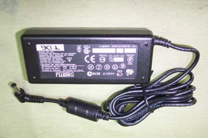
Click to zoom
Application Details
- Equipment Class
- DTS - Digital Transmission System
- Date of Grant
- Apr 17, 2003
- Application Purpose
- Original Equipment
- Date of Application
- Apr 17, 2003
- Equipment Note
- Notebook Computer With 802.11b and Bluetooth Modem
- Frequency Range
- 2412.00000000 - 2462.00000000
- Company
- Quanta Computer Inc
- Country
- Taiwan
Documents & Files
Document Text
Text extracted from the exhibit documents filed with the FCC. Open a document above to read the original.
Users Manual
TravelMate 800 series User’s guide Changes may be made periodically to the information in this publication without obligation to notify any person of such revision or changes. Such changes will be incorporated in new editions of this manual or supplementary documents and publications. This company makes no representations or warranties, either expressed or implied, with respect to the contents hereof and specifically disclaims the implied warranties of merchantability or fitness for a particular purpose. Record the model number, serial number, purchase date, and place of purchase information in the space provided below. The serial number and model number are recorded on the label affixed to your computer. All correspondence concerning your unit should include the serial number, model number, and purchase information. No part of this publication may be reproduced, stored in a retrieval system, or transmitted, in any form or by any means, electronic, mechanical, photocopy, recording, or otherwise, without the prior written permission of Acer Incorporated. Model number : _________________________________ Serial number: ___________________________________ Purchase date: ___________________________________ Place of purchase: ________________________________ Copyright © 2003 Acer Incorporated. All Rights Reserved. TravelMate 800 series User’s guide Original Issue: February 2003 TravelMate 800 series Notebook computer Acer and the Acer logo are registered trademarks of Acer Incorporated. Other company's product names or trademarks are used herein for identification purposes only and belong to their respective companies. iii English First things first We would like to thank you for making the TravelMate series of notebook computers your choice for your mobile computing needs. We hope you will be happy with your TravelMate as much as we enjoyed making it for you. Your guides To help you use your TravelMate, we have designed a set of guides: For more information about our products, services, and support information, please visit our Web site (global.acer.com). First off, the Just for Starters... poster helps you get started with setting up your computer. This User’s guide introduces you to the many ways your computer can help you be more productive. This guide provides clear and concise information about the computer, so read it thoroughly. If you ever need to print out a copy, this User’s guide is also available in PDF (Portable Document Format). Follow these steps: 1 Click on Start, Programs, TravelMate. 2 Click on TravelMate User’s guide. Note: Viewing the file requires Adobe Acrobat Reader installed. If Adobe Acrobat Reader is not installed on your computer, clicking on TravelMate User’s guide will run the Acrobat Reader setup program first. Follow the instructions on the screen to complete the installation. For instructions on how to use Adobe Acrobat Reader, access the Help menu. iv English Basic care and tips for using your computer Turning your computer on and off To turn on the computer, simply press the power button, the button left of the launch keys found above your TravelMate’s standard keyboard. See “Front open view” on page 3 for the location of the power switch. To turn the power off, do any of the following: •Use the Windows shutdown command For Windows 2000: Click on Start, Shut Down..., and select Shut down; then click on OK. - or - For Windows XP: Click on Start, Tur n off Computer; then click Turn Off. •Use the power button Note: You can also use the power button to perform power management functions. See Windows help for more information. •Use the customized functions for power management You can also shut down the computer by closing the display cover, or by pressing the sleep hot key (Fn-F4). See the online guide for details. Note: If you cannot power off the computer normally, press and hold the power switch for more than four seconds to shut down the computer. If you turn off the computer and want to turn it on again, wait at least two seconds before powering up. Taking care of your computer Your computer will serve you well if you take care of it. •Do not expose the computer to direct sunlight. Do not place it near sources of heat, such as a radiator. •Do not expose the computer to temperatures below 0ºC (32ºF) or above 50ºC (122ºF). v English •Do not subject the computer to magnetic fields. •Do not expose the computer to rain or moisture. •Do not spill water or any liquid on the computer. •Do not subject the computer to heavy shock and vibration. •Do not expose the computer to dust and dirt. •Never place objects on top of the computer to avoid damaging the computer. •Do not slam the computer display when you close it. •Never place the computer on uneven surfaces. Taking care of your AC adapter Here are some ways to take care of your AC adapter: •Do not connect the adapter to any other device. •Do not step on the power cord or place heavy objects on top of it. Carefully route the power cord and any cables away from personal traffic. •When unplugging the power cord, do not pull on the cord itself but pull on the plug. •The total ampere ratings of the equipment plugged in should not exceed the ampere rating of the cord if you are using an extension cord. Also, the total current rating of all equipment plugged into a single wall outlet should not exceed the fuse rating. Taking care of your battery pack Here are some ways to take care of your battery pack: •Use only batteries of the same kind as replacements. Turn the power off before removing or replacing batteries. •Do not tamper with batteries. Keep them away from children. •Dispose of used batteries according to local regulations. Recycle if at all possible. Cleaning and servicing When cleaning the computer, follow these steps: 1Power off the computer and remove the battery pack. vi English 2Disconnect the AC adapter. 3Use a soft cloth moistened with water. Do not use liquid or aerosol cleaners. 4To clean the display scr…
Text truncated - open the document above for the full version.
Users Manual
2 Customizing my computer48 English IEEE 1394 port The computer's IEEE 1394 port allows you to connect to an IEEE 1394 supported devices like a video camera or digital camera. See your video or digital camera's documentation for details. PC Card slot The type II CardBus PC Card slot found on the left side of the computer accepts credit-card-sized cards that enhance the usability and expandability of the computer. These cards should have a PC Card logo on them. PC Cards (formerly PCMCIA) are add-on cards for portable computers, giving you expansion possibilities long afforded by desktop PCs. Popular PC cards include flash, fax/data modem, LAN, wireless LAN and SCSI cards. CardBus improves on the 16-bit PC card technology by expanding the bandwidth to 32 bits. Note: Refer to your card’s manual for details on how to install and use the card and its functions. 49 English Inserting a PC Card Insert the card into the slot and make the proper connections (e.g., network cable), if necessary. See your card manual for details. Ejecting a PC Card Before ejecting a PC Card: 1Exit the application using the card. 2Left-click on the PC Card icon on the taskbar and stop the card operation. 3Press the slot eject button to pop out the eject button (a); then press it again to eject the card (b). 2 Customizing my computer50 English Port expansion devices Two types of expansion devices are available for your computer: •I/O replicator - adds serial port and parallel port connections to your computer. •EasyPort - adds a host of ports for your computer, and allows you to connect and disconnect peripherals from your computer in one quick step. See your dealer for more information. Upgrade options Your computer delivers superior power and performance. However, some users and the applications they use may demand more. This computer allows you to upgrade key components when you need increased performance. Note: Contact your authorized dealer if you decide to perform a key component upgrade. Memory upgrade Memory is expandable to 2 GB, employing 256/512/1024-MB industry standard soDIMMs (Small Outline Dual Inline Memory Modules). The computer supports DDR (Double Data Rate) RAM. There are two memory slots on your computer, one of which is occupied by standard memory. You can upgrade memory by installing a memory module into the one available slot, or replacing the standard memory with a higher-capacity memory module. Installing memory Follow these steps to install memory: 1Turn off the computer, unplug the AC adapter (if connected) and remove the battery pack. Then turn the computer over to access its base. 51 English 2Remove the screws from the memory cover (a); then lift up and remove the memory cover (b). 3Insert the memory module diagonally into the slot (a), then gently press it down (b) until it clicks into place. 4Replace the memory cover and secure it with the screw. 5Reinstall the battery pack, and reconnect the AC adapter. 6Turn on the computer. The computer automatically detects and reconfigures the total memory size. 2 Customizing my computer52 English Swapping AcerMedia drive modules Note: The hard disk drive module is not hot-swappable. You have to turn off your computer before you can swap the module. You can swap the AcerMedia drive with any optional AcerMedia modules. First slide the AcerMedia release latch as shown in the illustration (a). Then remove the optical drive from the AcerMedia bay (b). Then insert the optional AcerMedia module into the AcerMedia bay until the it click into place. 53 English Using system utilities Notebook Manager The computer has a built-in system setup program called Notebook Manager. The Windows-based Notebook Manager allows you to set passwords, the startup sequence of the drives, and power management settings. It also shows current hardware configurations. To start the Notebook Manager, press Fn-F2 or follow these steps: 1Click on Start, Programs, then Notebook Manager. 2Select the Notebook Manager application to run the program. Click on Help for more information. 2 Customizing my computer54 English Launch Manager Launch Manager allows you to set the five launch keys located above the keyboard. See “Touchpad” on page 22 for the location of the launch key. You can access the Launch Manager by clicking on Start, Programs, and then Launch Manager to start the application. BIOS Utility The BIOS Utility is a hardware configuration program built into your computer’s BIOS (basic input/output system). Your computer is already properly configured and optimized, and you do not need to run this utility. However, if you encounter configuration problems, you may need to run it. To activate the BIOS Utility, press F2 during the POST (power-on self- test) while the TravelMate logo is being displayed. 3 Troubleshooting my computer This chapter instructs you on how to deal with common system problems. Read it before calling a technician if a problem occurs. Solutions to more serious problems require opening up the computer. Do not attempt to open the computer by yourself. Contact your dealer or an authorized service center for assistance. key link: www.acersupport.com 57 English Frequently-asked questions The following is a list of possible situations that may arise during the use of your computer. Easy answers and solutions are provided for each one. I slid the power switch and opened the display, but the computer does not start or boot-up. Look at the Power indicator: •If it is not lit, no power is being applied to the computer. Check the following: •If you are running on battery power, it may be low and unable to power the computer. Connect the AC adapter to recharge the battery pack. •Make sure that the AC adapter is plugged in properly to the computer and to the power outlet. •If it is lit, check the following: •Is a non-bootable (non-system) CD in the optical drive? Remove or replace it with a system diskette and press Ctrl-Alt- Del to restart the system. •The operating system…
Text truncated - open the document above for the full version.
External Photos
Report Number:021367-T December 25, 2002 Page 83 Rev. 00 Open view of EUT (14”) Open view of EUT (15”) Report Number:021367-T December 25, 2002 Page 84 Rev. 00 Front View of EUT Back View of EUT Report Number:021367-T December 25, 2002 Page 85 Rev. 00 Left View of EUT Right View of EUT Report Number:021367-T December 25, 2002 Page 86 Rev. 00 Bottom View of EUT One to Two Adapter Report Number:021367-T December 25, 2002 Page 87 Rev. 00 Power Adapter (DELTA / ADP-75FB) Report Number:021367-T December 25, 2002 Page 88 Rev. 00 Power Adapter (LITEON / PA-1750-02)
External Photos
FCC ID: PD9WM3B2100 View with Transmitter Outside of the Host Desktop Computer FCC ID: PD9WM3B2100 Top View “Hitachi Antennas” FCC ID: PD9WM3B2100 Bottom View “Hitachi Antennas” FCC ID: PD9WM3B2100 Cable Length Between Antenna and Device “Hitachi Antennas” 20 inch coax cable FCC ID: PD9WM3B2100 Top View “Ethetronics Antennas” FCC ID: PD9WM3B2100 Bottom View “Ethertronics Antennas” FCC ID: PD9WM3B2100 Cable Length Between Antenna and Device “Ethertronics Antennas” 20 inch coax cable
Internal Photos
Report Number:021367-T December 25, 2002 Page 90 Rev. 00 Internal of EUT---1 Internal of EUT---2 Report Number:021367-T December 25, 2002 Page 91 Rev. 00 Internal of EUT---3 Internal of EUT---4 Report Number:021367-T December 25, 2002 Page 92 Rev. 00 Internal of EUT---5 Internal of EUT---6 Report Number:021367-T December 25, 2002 Page 93 Rev. 00 Internal of EUT---7 Internal of EUT---8 Report Number:021367-T December 25, 2002 Page 94 Rev. 00 Internal of EUT---9 Internal of EUT---10 Report Number:021367-T December 25, 2002 Page 95 Rev. 00 Internal of EUT---11 Internal of EUT---12 Report Number:021367-T December 25, 2002 Page 96 Rev. 00 Internal of EUT---13 Internal of EUT---14 Report Number:021367-T December 25, 2002 Page 97 Rev. 00 Internal of EUT---15 Internal of EUT---16 Report Number:021367-T December 25, 2002 Page 98 Rev. 00 Internal of EUT---17 Internal of EUT---18 Report Number:021367-T December 25, 2002 Page 99 Rev. 00 Internal of EUT---19 Internal of EUT---20 Report Number:021367-T December 25, 2002 Page 100 Rev. 00 Internal of EUT---21 Internal of EUT---22 Report Number:021367-T December 25, 2002 Page 101 Rev. 00 Internal of EUT---23
Parts List/Tune Up Info
Prepared By: NWInG-CABLE-ME Shwan Hung page1 Date : 2003/02/18 FOXCONN NWInG Antenna Engineering Test Report Quanta ZG1S WLAN Antenna Prepared By: NWInG-CABLE-ME Shwan Hung page2 Date : 2003/02/18 Prepared By: NWInG-CABLE-ME Shwan Hung page3 Date : 2003/02/18 VSWR of Blue-tooth Antenna VS W R 123456 2 2.5 3 3.5 4 F r e q ( GHz ) SWR 2.4 GHz = 2.3412.45GHz = 1.3372.5 GHz = 1.618 Cable length = 73.5 mm Prepared By: NWInG-CABLE-ME Shwan Hung page4 Date : 2003/02/18 X-Y Plane Radiation Pattern of WLAN BT Antenna 2.4GHz~2.5GHz HORIZONTAL POLARIZATION VERTICAL POLARIZATION Prepared By: NWInG-CABLE-ME Shwan Hung page5 Date : 2003/02/18 X-Y Plane Gain of Blue-tooth Antenna Average Gain ( d B i ) 2 400M H z 2450 M H z 2500 M H z X Y - H - 6.74 - 6 .04 - 5.67 X Y - V - 5.22 - 4 .78 - 3.72 X Y - A V G . - 2 .90 - 2.35 - 1 .58 Peak Gain ( d B i ) 2 400M H z 2450 M H z 2500 M H z X Y - r i g h t - H 0.95 1.36 1.36 X Y -r i g h t -V 0 . 2 1 -0 . 1 1 1 . 1 0 Prepared By: NWInG-CABLE-ME Shwan Hung page6 Date : 2003/02/18 VSWR of WLAN Right Antenna VS W R 123456 2 2.5 3 3.5 4 4.5 5 5.5 6 F r e q ( GHz ) SWR 2.4 GHz = 1.8492.45GHz = 1.1282.5 GHz = 1.6065.15 GHz = 1.9015.25 GHz = 1.7025.35 GHz = 1.802 Cable length = 492 mm Prepared By: NWInG-CABLE-ME Shwan Hung page7 Date : 2003/02/18 X-Y Plane Radiation Pattern of WLAN Right Antenna 2.4GHz~2.5GHz HORIZONTAL POLARIZATION VERTICAL POLARIZATION Prepared By: NWInG-CABLE-ME Shwan Hung page8 Date : 2003/02/18 X-Y Plane Radiation Pattern of WLAN Right Antenna 5.15GHz~5.35GHz HORIZONTAL POLARIZATION VERTICAL POLARIZATION Prepared By: NWInG-CABLE-ME Shwan Hung page9 Date : 2003/02/18 X-Y Plane Gain of WLAN Right Antenna Average Gain F r e q ( G H z ) 2 .4 2.45 2.5 5 .15 5 .25 5 .35 X Y -H (d B i ) - 11.31 - 10.62 - 11.58 - 17.27 - 17.20 - 17.59 XY- V ( d B i ) - 10.80 - 9 .77 - 9.83 - 8 .62 - 7.86 - 7 .65 A v e r age G a i n - 8 .03 - 7.16 - 7 .61 - 8.06 - 7 .38 - 7.23 Peak Gain F r e q ( G H z ) 2 .4 2.45 2.5 5 .15 5 .25 5 .35 X Y -H (d B i ) - 5 .73 - 4.57 - 5 .00 - 10.65 - 1 0.14 - 9 .24 X Y -V (d B i ) - 3 .63 - 4.32 - 2 .67 - 1.82 0.01 1.25 Prepared By: NWInG-CABLE-ME Shwan Hung page10 Date : 2003/02/18 VSWR of WLAN Left Antenna VS W R 123456 2 2.5 3 3.5 4 4.5 5 5.5 6 Fr e q ( G H z ) SWR 2.4 GHz = 1.7512.45GHz = 1.6622.5 GHz = 1.9435.15 GHz = 1.8205.25 GHz = 1.3255.35 GHz = 1.884 Cable length = 340 mm Prepared By: NWInG-CABLE-ME Shwan Hung page11 Date : 2003/02/18 X-Y Plane Radiation Pattern of WLAN Left Antenna 2.4GHz~2.5GHz HORIZONTAL POLARIZATION VERTICAL POLARIZATION Prepared By: NWInG-CABLE-ME Shwan Hung page12 Date : 2003/02/18 X-Y Plane Radiation Pattern of WLAN Left Antenna 5.15GHz~5.35GHz HORIZONTAL POLARIZATION VERTICAL POLARIZATION Prepared By: NWInG-CABLE-ME Shwan Hung page13 Date : 2003/02/18 X-Y Plane Gain of WLAN Left Antenna Average Gain F r e q ( G H z ) 2 .4 2.45 2.5 5 .15 5 .25 5 .35 X Y -H (d B i ) - 17.23 - 15.61 - 17.35 - 15.25 - 13.96 - 14.16 XY- V ( d B i ) - 9 .17 - 8.05 - 9 .52 - 8.21 - 8 .37 - 9.92 A v e r age G a i n - 8 .54 - 7.35 - 8 .85 - 7.43 - 7 .31 - 8.53 Peak Gain F r e q ( G H z ) 2 .4 2.45 2.5 5 .15 5 .25 5 .35 X Y -H (d B i ) - 1 0.69 - 9 .15 - 9.99 - 8 .72 - 7.88 - 5 .61 X Y -V (d B i ) - 3 .14 - 1.76 - 4 .03 - 0.90 - 0 .11 - 2.03
RF Exposure Info
in accordance with the requirements of FCC Report and Order: ET Docket 93-62, and OET Bulletin 65 Supplement C for Notebook Computer With 802.11b Wireless LAN and Bluetooth Modem MODEL: ZG1S FCC ID: HFSZG1SWM3B2100BT February 18, 2003 REPORT NO: 03T1782-2B Prepared for Quanta Computer Inc. No. 188, Wen Hwa 2 nd Road Kuei Shan Hsiang, Tao Yuan Shien Taiwan, R. O. C. Prepared by COMPLIANCE CERTIFICATION SERVICES 561F MONTEREY ROAD MORGAN HILL, CA 95037 USA TEL: (408) 463-0885 REPORT NO: 03T1782-2B DATE: February 18, 2003 FCC ID: HFSZG1SWM3B2100BT COMPLIANCE CERTIFICATION SERVICES Page: 2 of 22 This report shall not be reproduced except in full, without the written approval of CCS. This document may be altered or revised by Compliance Certification Services personnel only, and shall be noted in the revision section of the document. CERTIFICATE OF COMPLIANCE (SAR EVALUATION) Date of Tests: February 18, 2003 Report No: 03T1782-2B APPLICANT: Quanta Computer Inc. No. 188, Wen Hwa 2nd Road Kuei Shan Hsiang, Tao Yuan Shien Taiwan, R. O. C. MODEL: ZG1S FCC ID: HFSZG1SWM3B2100BT DEVICE CATEGORY: PORTABLE DEVICES EXPOSURE CATEGORY: GENERAL POPULATION/UNCONTROLLED EXPOSURE Test Sample is a: Production unit Modulation type: DSSS - 802.11b Wireless LAN DSSS - Bluetooth Tx Frequency: Wireless LAN - 2412 ~ 2462 MHz Bluetooth - 2402 ~ 2480 MHz Max. O/P Power (Conducted): Wireless LAN - 16.89 dBm Max. SAR (1g): Wireless LAN - 0.00606 mW/g Co-Location - 0.00831 mW/g Application Type: Certification FCC Rule Part(s): §15.247 This wireless portable device has been shown to be capable of compliance for localized specific absorption rate (SAR) for uncontrolled environment/general population exposure limits specified in ANSI/IEEE Std. C95.1-1992 and had been tested in accordance with the measurement procedures specified in FCC OET 65 Supplement C (released on 6/29/2001 see Test Report). I attest to the accuracy of data. All measurements reported herein were performed by me or were made under my supervision and are correct to the best of my knowledge and belief. I assume full responsibility for the completeness of these measurements and vouch for the qualifications of all persons taking them. Steve Cheng EMC Engineering Manager REPORT NO: 03T1782-2B DATE: February 18, 2003 FCC ID: HFSZG1SWM3B2100BT COMPLIANCE CERTIFICATION SERVICES Page: 3 of 22 This report shall not be reproduced except in full, without the written approval of CCS. This document may be altered or revised by Compliance Certification Services personnel only, and shall be noted in the revision section of the document. TABLE OF CONTENT 1. EUT DESCRIPTION........................................................................................................4 2. REQUIREMENTS FOR COMPLIANCE TESTING DEFINED BY THE FCC.................5 3. DOSIMETRIC ASSESSMENT SYSTEM........................................................................5 3.1. MEASUREMENT SYSTEM DIAGRAM.......................................................................................................6 3.2. SYSTEM COMPONENTS..............................................................................................................................7 4. EVALUATION PROCEDURE..........................................................................................9 5. MEASUREMENT UNCERTAINTY................................................................................12 6. EXPOSURE LIMIT.........................................................................................................13 7. MEASUREMENT RESULTS.........................................................................................14 7.1. SYSTEM VALIDATION.................................................................................................................................14 7.2. TEST LIQUID CONFIRMATION.................................................................................................................15 7.3. EUT TUNE-UP PROCEDURE....................................................................................................................16 7.4. EUT SETUP PHOTOS.................................................................................................................................17 7.5. SAR MEASUREMENT RESULTS..............................................................................................................18 8. EUT PHOTOS................................................................................................................19 9. EQUIPMENTS LIST & CALIBRATION STATUS.........................................................20 10. REFERENCES...............................................................................................................21 11. ATTACHMENT..............................................................................................................22 REPORT NO: 03T1782-2B DATE: February 18, 2003 FCC ID: HFSZG1SWM3B2100BT COMPLIANCE CERTIFICATION SERVICES Page: 4 of 22 This report shall not be reproduced except in full, without the written approval of CCS. This document may be altered or revised by Compliance Certification Services personnel only, and shall be noted in the revision section of the document. 1. EUT DESCRIPTION APPLICANT: Quanta Computer Inc. No. 188, Wen Hwa 2nd Road Kuei Shan Hsiang, Tao Yuan Shien Taiwan, R. O. C. MODEL: ZG1S FCC ID: HFSZG1SWM3B2100BT DEVICE CATEGORY: PORTABLE DEVICES EXPOSURE CATEGORY: GENERAL POPULATION/UNCONTROLLED EXPOSURE Test Sample is a: Production unit Modulation type: DSSS - 802.11b Wireless LAN DSSS - Bluetooth Tx Frequency: Wireless LAN - 2412 ~ 2462 MHz Bluetooth - 2402 ~ 2480 MHz Max. O/P Power (Conducted): Wireless LAN - 16.89 dBm Max. SAR (1g): Wireless LAN - 0.00606 mW/g Co-Location - 0.00831 mW/g Application Type: Certification FCC Rule Part(s): §15.247 Wireless Module: 1. Wireless LAN - Manufactured “Intel”, model “WM3B2100”, FCC ID “PD9WM3B2100” 2. Bluetooth - Manufactured “Ambit ”, m…
Text truncated - open the document above for the full version.
RF Exposure Info
Date/Time: 02/18/03 10:25:47 Test Laboratory: Compliance Certification Services File Name: D2450V2_021803_14.1mW.da4 DUT: Dipole Type & Serial Number: D2450V2 SN 706 Program: System Validation Communication System: D2450V2 SN 706; Frequency: 2450 MHz; Duty Cycle: 1:1 Medium: Head 2450 MHz ( σ = 1.8754 mho/m, ε = 39.37, ρ = 1000 kg/m3) Phantom section: FlatSection DASY4 Configuration: - Probe: ET3DV6 - SN1578; ConvF(4.5, 4.5, 4.5); Calibrated: 2/22/2002 - Sensor-Surface: 4mm (Mechanical Surface Detection) - Electronics: DAE3 Sn500; Calibrated: 2/26/2002 - Phantom: SAM 1 - TP: 1185 - Software: DASY4, V4.0 Build 51 Area Scan (9x9x1): Measurement grid: dx=10mm, dy=10mm Zoom Scan (5x5x7)/Cube 0: Measurement grid: dx=7.5mm, dy=7.5mm Reference Value = 87.5 V/m Peak SAR = 38.59 mW/g SAR(1 g) = 14.1 mW/g; SAR(10 g) = 5.9 mW/g Power Drift = -0.04 dB SAR in dB -23.7 -21.3 -18.9 -16.6 -14.2 -11.8 -9.46 -7.1 -4.73 -2.37 0
Test Setup Photos
REPORT NO: 03T1782-1 DATE: FEBUARY 13, 2003 EUT: NOTE BOOK WITH 802.11b WLAN AND BLUETOOTH FCC ID: HFSZGISWM3B2100 Page 31 of 36 COMPLIANCE CERTIFICATION SERVICES DOCUMENT NO: CCSUP4031A 561F MONTEREY ROAD, MORGAN HILL, CA 95037 USA TEL: (408) 463-0885 FAX: (408) 463-0888 This report shall not be reproduced except in full, without the written approval of CCS. This document may be altered or revised by Compliance Certification Services personnel only, and shall be noted in the revision section of the document. 9. SETUP PHOTOS SETUP PHOTOS FOR TRANSMITTER TESTING REPORT NO: 03T1782-1 DATE: FEBUARY 13, 2003 EUT: NOTE BOOK WITH 802.11b WLAN AND BLUETOOTH FCC ID: HFSZGISWM3B2100 Page 32 of 36 COMPLIANCE CERTIFICATION SERVICES DOCUMENT NO: CCSUP4031A 561F MONTEREY ROAD, MORGAN HILL, CA 95037 USA TEL: (408) 463-0885 FAX: (408) 463-0888 This report shall not be reproduced except in full, without the written approval of CCS. This document may be altered or revised by Compliance Certification Services personnel only, and shall be noted in the revision section of the document. REPORT NO: 03T1782-1 DATE: FEBUARY 13, 2003 EUT: NOTE BOOK WITH 802.11b WLAN AND BLUETOOTH FCC ID: HFSZGISWM3B2100 Page 33 of 36 COMPLIANCE CERTIFICATION SERVICES DOCUMENT NO: CCSUP4031A 561F MONTEREY ROAD, MORGAN HILL, CA 95037 USA TEL: (408) 463-0885 FAX: (408) 463-0888 This report shall not be reproduced except in full, without the written approval of CCS. This document may be altered or revised by Compliance Certification Services personnel only, and shall be noted in the revision section of the document. SETUP PHOTOS FOR DIGITAL DEVICE TESTING REPORT NO: 03T1782-1 DATE: FEBUARY 13, 2003 EUT: NOTE BOOK WITH 802.11b WLAN AND BLUETOOTH FCC ID: HFSZGISWM3B2100 Page 34 of 36 COMPLIANCE CERTIFICATION SERVICES DOCUMENT NO: CCSUP4031A 561F MONTEREY ROAD, MORGAN HILL, CA 95037 USA TEL: (408) 463-0885 FAX: (408) 463-0888 This report shall not be reproduced except in full, without the written approval of CCS. This document may be altered or revised by Compliance Certification Services personnel only, and shall be noted in the revision section of the document. REPORT NO: 03T1782-1 DATE: FEBUARY 13, 2003 EUT: NOTE BOOK WITH 802.11b WLAN AND BLUETOOTH FCC ID: HFSZGISWM3B2100 Page 35 of 36 COMPLIANCE CERTIFICATION SERVICES DOCUMENT NO: CCSUP4031A 561F MONTEREY ROAD, MORGAN HILL, CA 95037 USA TEL: (408) 463-0885 FAX: (408) 463-0888 This report shall not be reproduced except in full, without the written approval of CCS. This document may be altered or revised by Compliance Certification Services personnel only, and shall be noted in the revision section of the document. LINE CONDUCTION SETUP PHOTO REPORT NO: 03T1782-1 DATE: FEBUARY 13, 2003 EUT: NOTE BOOK WITH 802.11b WLAN AND BLUETOOTH FCC ID: HFSZGISWM3B2100 Page 36 of 36 COMPLIANCE CERTIFICATION SERVICES DOCUMENT NO: CCSUP4031A 561F MONTEREY ROAD, MORGAN HILL, CA 95037 USA TEL: (408) 463-0885 FAX: (408) 463-0888 This report shall not be reproduced except in full, without the written approval of CCS. This document may be altered or revised by Compliance Certification Services personnel only, and shall be noted in the revision section of the document. END OF REPORT
Contact Information
Applicant
Joyce Kuo
Test Firm
Compliance Certification Services IncSteve Cheng
Technical Specifications
| # | Rule Parts | Frequency Range | Power Output |
|---|---|---|---|
| 1 | 15C | 2.41 GHz - 2.46 GHz | 47.00 mW |
Other Applications from Quanta Computer Inc
HFS-QV28NRW
Jul 15, 2026Telematics Module
Equipment Class
PCB - PCS Licensed TransmitterHFSCIP
Jun 15, 2026QOCA ecg1202
Equipment Class
DTS - Digital Transmission System
HFS-QV28NUS
Apr 16, 2026Telematics Module
Equipment Class
PCB - PCS Licensed TransmitterHFS-C407
Jul 21, 2024Clover Flex Pocket
Equipment Class
NII - Unlicensed National Information Infrastructure TXHFS-C406
Jul 01, 2024Clover Flex
Equipment Class
DTS - Digital Transmission System