HFSZI3RM8NoteBook Personal Computer
Quanta Computer Inc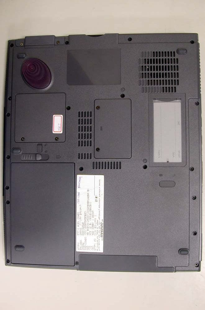
Click to zoom
Application Details
- Equipment Class
- DTS - Digital Transmission System
- Date of Grant
- Oct 23, 2003
- Application Purpose
- Original Equipment
- Date of Application
- Oct 23, 2003
- Equipment Note
- NoteBook Personal Computer
- Frequency Range
- 2412.00000000 - 2462.00000000
- Company
- Quanta Computer Inc
- Country
- Taiwan
Documents & Files
Document Text
Text extracted from the exhibit documents filed with the FCC. Open a document above to read the original.
Users Manual
Acer Aspire 1450 series User’s guide Changes may be made periodically to the information in this publication without obligation to notify any person of such revision or changes. Such changes will be incorporated in new editions of this manual or supplementary documents and publications. This company makes no representations or warranties, either expressed or implied, with respect to the contents hereof and specifically disclaims the implied warranties of merchantability or fitness for a particular purpose. Record the model number, serial number, purchase date, and place of purchase information in the space provided below. The serial number and model number are recorded on the label affixed to your computer. All correspondense concerning your unit should include the serial number, model number, and purchase information. No part of this publication may be reproduced, stored in a retrieval system, or transmitted, in any form or by any means, electronic, mechanical, photocopy, recording, or otherwise, without the prior written permission of Acer Incorporated. Model Number : _________________________________ Serial Number: ___________________________________ Purchase Date: ___________________________________ Place of Purchase: ________________________________ Copyright © 2003 All Rights Reserved Acer Aspire 1450 Series Notebook Computer User's Guide Original Issue: September 2003 Acer Aspire 1450 series Notebook computer All trademarks and registered trademarks are the properties of their respective companies. iii English English First things first Your guides A set of guides is provided to help you set up and use your Aspire computer.: For more information on our products, services, and support, please visit our web site: www.global.acer.com. Basic care and tips for using your computer Turning your computer on and off To turn on your computer, open the lid and press the power button above the keyboard. To turn the power off, you can do any of the following: •Click on the Start button in Windows, and then select Shut Down on the popup menu. •Push the power button. To use this method, you must first click on the Power Management icon in Windows Control Panel, and then check that the power button is set to shut down the computer when pressed. See Windows Help for more information. The Just for starters... poster shows you how to set up your computer. This User's Guide provides clear and concise information on using your computer productively. You are advised to read it thoroughly and keep it handy for future reference. iv English Note: If you are unable to shut down the computer in the usual way, press and hold the power button for more than four seconds. You should then wait at least two seconds before turning the computer on again. Taking care of your computer Your computer will serve you well if you take care of it. •Do not expose the computer to direct sunlight. Do not place it near sources of heat, such as a radiator. •Do not expose the computer to temperatures below 0°C (32°F), or above 50°C (122°F). •Do not expose the computer to magnetic fields. •Do not expose the computer to rain or moisture. •Do not spill water or any liquid on the computer. •Do not subject the computer to heavy shock or vibration. •Do not expose the computer to dust or dirt. •Do not place objects on top of the computer. •Do not slam the lid shut. Close the computer gently. •Do not place the computer on unstable or uneven surfaces. Taking care of your AC adapter It is important that you look after your AC adapter. •Do not connect the adapter to any other device. •Do not step on the power cord or place heavy objects on it. Route the power cord away from areas where people might walk on it or trip over it. •Do not pull on the power cord when disconnecting from the mains power socket. Grasp and pull the plug instead. •The total ampere ratings of equipment plugged into a power strip should not exceed the ampere rating for that power strip. v English English Taking care of your battery pack It is also important that you look after your computer's battery pack. •Use the correct battery model for your computer. Do not use other kinds of batteries. •Turn the power off before removing or replacing the battery. •Do not tamper with the battery. Keep the battery away from children. •Dispose of batteries according to local regulations. Recycle if possible. Cleaning and servicing When cleaning your computer, it is important that you follow these steps: •Turn off the computer and remove the battery. •Disconnect the AC adapter. •Clean with a soft cloth moistened with a little water. Do not use liquid or aerosol cleaners. Refer to the chapter entitled “Frequently asked questions” on page 67 if any of the following occurs: •You drop the computer or damage the case. •You spill liquid on the computer. •The computer does not operate normally. vi English English First things firstiii Your guidesiii Basic care and tips for using your computeriii Getting familiar with your computer1 A tour of your computer3 Front open view3 Front view4 Left view 6 Right view 7 Rear view8 Bottom view9 Features11 Indicators13 Using the Keyboard14 Special keys14 Touchpad21 Touchpad basics21 Launch Keys23 24 Storage25 Hard disk25 Optical drive25 Emergency ejection of the optical drive tray26 Audio27 Adjusting the volume27 Connectivity options28 Ethernet and LAN28 Fax/data modem29 Fast infrared30 Securing your computer31 Using a computer security lock31 Using passwords31 Operating on battery power33 Battery pack35 Battery pack characteristics35 Installing and removing the battery pack36 Charging the battery37 Checking the battery level37 Contents English Optimizing battery life37 Battery-low warning38 Power management39 Peripherals and options41 External display devices43 External input devices43 External keyboard43 External keypad43 External pointing device43 USB devices44 IEEE 1394 Port45 Printer46 Audio devices46 Expansion devices47 PC Card47 Miscellaneous opt…
Text truncated - open the document above for the full version.
Users Manual
WLAN 802.11g mini-PCI Module User Manual Version: 1.0 Sep. 2003 1 Copyright Statement No part of this publication may be reproduced, stored in a retrieval system, or transmitted in any form or by any means, whether electronic, mechanical, photocopying, recording or otherwise without the prior writing of the publisher. Windows ™ 98SE/2000/ME/XP are trademarks of Microsoft ® Corp. Pentium is trademark of Intel. All copyright reserved. 2 Federal Communication Commission Interference Statement This equipment has been tested and found to comply with the limits for a Class B digital device, pursuant to Part 15 of the FCC Rules. These limits are designed to provide reasonable protection against harmful interference in a residential installation. This equipment generates, uses and can radiate radio frequency energy and, if not installed and used in accordance with the instructions, may cause harmful interference to radio communications. However, there is no guarantee that interference will not occur in a particular installation. If this equipment does cause harmful interference to radio or television reception, which can be determined by turning the equipment off and on, the user is encouraged to try to correct the interference by one of the following measures: - Reorient or relocate the receiving antenna. - Increase the separation between the equipment and receiver. - Connect the equipment into an outlet on a circuit different from that to which the receiver is connected. - Consult the dealer or an experienced radio/TV technician for help. FCC Caution: To assure continued compliance, (example - use only shielded interface cables when connecting to computer or peripheral devices) any changes or modifications not expressly approved by the party responsible for compliance could void the user's authority to operate this equipment. This device complies with Part 15 of the FCC Rules. Operation is subject to the following two conditions: (1) This device may not cause harmful interference, and (2) This device must accept any interference received, including interference that may cause undesired operation. IMPORTANT NOTE: This transmitter must not be co-located or operating in conjunction with any other antenna or transmitter. 3 Table of Contents 1. INTRODUCTION 4 1.1 THE WLAN 802.11G MINI-PCI MODULE..............................................................4 1.2 FEATURES................................................................................................................4 2. PLANNING YOUR WIRELESS NETWORK 5 2.1 NETWORK TOPOLOGY.............................................................................................5 2.2 AD-HOC VERSUS INFRASTRUCTURE MODE............................................................5 3. SOFTWARE INSTALLATION AND UNINSTALLATION 7 3.1 SETUP WIZARD INSTALLATION.......................................................................7 3.2 ADDITIONAL SETUP PROCESSES.............................................................................9 3.3 DISABLE WINDOWS XP ZERO-CONFIGURATION.................................................11 3.4 UNINSTALLATION...................................................................................................12 4. USING THE CONFIGURATION UTILITY 14 4.1 OVERVIEW.............................................................................................................14 4.2 ACCESSING THE CONFIGURATION UTILITY.........................................................14 4.3 LINK STATUS..........................................................................................................18 4.4 SITE MONITOR.......................................................................................................19 4.5 STATISTICS.............................................................................................................20 4.6 DIAGNOSTICS.........................................................................................................21 4.7 INFORMATION........................................................................................................22 APPENDIX A: TROUBLESHOOTING23 APPENDIX B: GLOSSARY 26 APPENDIX C: SPECIFICATION 31 4 1. Introduction 1.1 The WLAN 802.11g mini-PCI Module 802.11g is the 54Mbps wireless networking standard that's almost five times faster than the widely deployed 802.11b products found in homes, businesses, and public wireless hotspots around the country — but since they share the same 2.4GHz radio band, 802.11g devices can also work with existing 11Mbps 802.11b equipment. The new 802.11g mini-PCI Module has both standards built in, so you can connect your notebook to existing 802.11b infrastructure, and also the new screaming fast 802.11g networks. The included Setup Wizard will walk you through configuring the module to your network's settings, step by step. Once you're connected, you can keep in touch with your e-mail, access the Internet, and share files and other resources such as printers and network storage with other computers on the network, wherever you wander. At home, you can surf the web or use instant messaging to chat with friends while sitting out on the patio. You'll also be able to connect with any of the growing number of public wireless hotspots springing up in coffee shops, airport lounges, hotels and convention centers. And as those hotspots upgrade to the new high-speed 802.11g standard, you'll be ready to take advantage of the increased speeds. Get connected to current-standard 802.11b networks today, and be prepared for the future with the WLAN 802.11g mini-PCI Module. 1.2 Features l High-speed 802.11g networking for your notebook computer l Data rates up to 54Mbps -- 5 times faster than 802.11b l Also interoperates with 802.11b networks (at 11Mbps) l Wireless security -- up to 128-bit WEP encryption 5 2. Planning Your Wireless Network 2.1 Network Topology A wireless local area network (WLAN) is exactly like a regular local area network (LAN), exce…
Text truncated - open the document above for the full version.
Cover Letter(s)
Rev 2 C:\tmp\03LR018 ZI3\FCC\AP FORM.doc 02/08/02 American Telecommunications Certification Body, Inc. 6731 Whittier Avenue McLean, VA 22101 Ph: (703) 847-4700 FAX: (703) 847-6888 Certification Application Package AmericanTCB CERTIFICATION APPLICATION Rev 2 C:\tmp\03LR018 ZI3\FCC\AP FORM.doc 02/08/02 Quanta Computer Inc. 7F, 116, Hou Kang St., Shih Lin, Taipei Taiwan, R. O. C. This TESTING AND CERTIFICATION AGREEMENT ("Agreement") is made effective as of the latter date of execution below, by and between American Telecommunication Certification Body (ATCB) and Quanta Computer Inc. (Applicant), collectively referred to as "the Parties". Equipment Description Equipment Description: Notebook Personal Computer Model Number: Aspire 1450; ZI3 FCC Rule Part(s): 15C In consideration of the mutual covenants in this Agreement, ATCB or its subcontractors will perform certification inspection services to determine if Applicant's device(s) identified above under Equipment Description (hereinafter "Devices") are in compliance with the laws, regulations and technical standards (hereinafter "Certification Regulations") of the national authorities specified by Applicant in Schedule A. 1. General 1.1 This Agreement is for the purpose of testing and certification and applies to all tests, audits, and certifications for the Devices, and will be performed in accordance with the Certification Regulations of the national authorities specified in Schedule A. 1.2 ATCB retains full discretion to determine if the Devices are compliant with the Certification Regulations of the Countries. In the event that certification is not issued for the aforementioned Devices, ATCB agrees to advise Applicant in writing of the reasons thereof. 1.3 This Agreement may not be assigned to or acquired by any other person, firm, or corporation without ATCB's written authorization. 2. Scope of Performance 2.1 The scope of performance between the Parties shall be agreed to by contract, purchase order or other mutually agreed-upon schedule or order. 2.2 Except as provided in Section 2.3 hereof, testing of all Devices shall take place at ATCB facilities. 2.3 In lieu of section 2.2 above, ATCB may agree to accept test data from any ISO/IEC Guide 25 accredited laboratory or FCC-Listed Laboratory and evaluate the Devices on the basis of this data. ATCB may also choose to accept test data from ISO Guide 25 accredited laboratories owned by Applicant, provided the requirements of 2.3.1. are met. 2.3.1 Employees of Applicant shall not participate in any tests, evaluations, or assessments described in sections 2.2 or 2.3 above without the presence and supervision of an ATCB engineer or technician. 2.4 If requested for sample purposes (as required by the FCC), client shall supply ATCB, at no charge, with at least one test sample of each Device, including the necessary peripherals, connecting cables, accessories or other hardware or software (hereinafter collectively referred to as "support equipment") required for testing, evaluation, and assessment. 2.5 Applicant shall supply ATCB, at no charge, with all technical documentation and materials required for the testing, evaluation, and assessment of such Devices and support equipment. 2.5.1 Technical documentation and materials include, but are not limited to, any relevant operating instructions, schematics, block diagrams, photographs, prior tests and certificates concerning the safety of the Devices, its components or support equipment. 2.6 Applicant recognizes that Device samples, including support equipment, may be damaged or completely destroyed when subjected to ATCB's testing and evaluation process. Applicant shall hold ATCB harmless for any such damage or destruction to its equipment. 2.7 If necessary ATCB shall test, evaluate, or assess Applicant's equipment within 30 business days of ATCB's receipt of such Devices, support equipment and technical documentation, and to work diligently until certification is granted or denied, or Applicant decides to abandon testing, evaluation, and assessment on such Devices. AmericanTCB CERTIFICATION APPLICATION Rev 2 C:\tmp\03LR018 ZI3\FCC\AP FORM.doc 02/08/02 2.8 Upon completion of testing, evaluation, or assessment, ATCB shall advise Applicant via an abbreviated report whether the results are favorable, and what, if any, conditions, limitations or qualifications to the requested Certification exist. 2.9 Applicant agrees that a full report is available to Applicant only by special request, and for the separate charge specified. 2.10 Where testing, evaluation, and assessment results in certification, ATCB shall certify Applicant's equipment as compliant with the laws, regulations and/or standards of the Countries within 30 business days from the date testing, evaluation, and assessment is completed. 2.10.1 Section 2.11 may be dependent upon a timely response by the United States Federal Communications Commission (FCC) or its foreign equivalent. 2.10.2 In the event of product certification, Applicant may request that ATCB return or destroy Applicant's Device sample(s), equipment support, and technical documentation. Applicant shall bear all costs associated with the return or destruction of such equipment test sample(s) and support equipment. 2.11 Where testing, evaluation, and assessment does not result in certification, ATCB shall provide cost-free storage for each Device sample, support equipment, and technical documentation for a period not to exceed 30 days, provided Applicant agrees to re-testing within this period when notified of the Device's failure. 2.12 If Applicant does not collect or accept receipt of the Device sample(s), support equipment and technical documentation, despite ATCB having sent notice pursuant to subsection 2.12.1, ATCB reserves the right to dispose of them at Applicant's expense. 2.13 Applicant shall retain all documents forwarded to it by ATCB as required by the Certification Regulations of the Countries. 2.14 Applicant shall…
Text truncated - open the document above for the full version.
External Photos
EUT-1 EUT-2 EUT-3
ID Label/Location Info
Label Location Label Location
Internal Photos
EUT-1 EUT-2 EUT-3 EUT-4 EUT-5 EUT-6 EUT-7
RF Exposure Info
Prepared By: NWInG-CABLE-ME Mike Ke page1 Date : 2003/9/4 FOXCONN NWInG Antenna Engineering Test Report Quanta ZI3 WLAN Antenna Prepared By: NWInG-CABLE-ME Mike Ke page2 Date : 2003/9/4 HORIZONTAL POLARIZATIONX-Y Plane Radiation Pattern of WLAN Left Antenna for 6/25’03 Report (for 14” panel) 2.4GHz~2.5GHz HORIZONTAL POLARIZATION VERTICAL POLARIZATION 5.15GHz~5.35GHz VERTICAL POLARIZATION Prepared By: NWInG-CABLE-ME Mike Ke page3 Date : 2003/9/4 X-Y Plane Radiation Pattern of WLAN Right Antenna for 6/25’03 Report (for 14” panel ) 2.4GHz~2.5GHz HORIZONTAL POLARIZATION VERTICAL POLARIZATION 5.15GHz~5.35GHz HORIZONTAL POLARIZATION VERTICAL POLARIZATION Prepared By: NWInG-CABLE-ME Mike Ke page4 Date : 2003/9/4 Average Gain (Left) Peak Gain (Left) Freq(GHz) 2.4 2.45 2.5 5.15 5.25 5.35 XY-H(dBi) -8.35 -8.18 -8.71 -10.10 -9.02 -7.66 XY-V(dBi) -4.67 -4.80 -5.59 -5.48 -4.56 -4.85 Average Gain -3.12 -3.16 -3.86 -4.19 -3.23 -3.02 Freq(GHz) 2.4 2.45 2.5 5.15 5.25 5.35 XY-H(dBi) -3.65 -3.66 -3.58 -3.22 -2.36 -2.46 XY-V(dBi) 3.34 0.92 0.60 0.31 1.85 1.51 Average Gain (Right) Peak Gain (Right) X-Y Plane Gain of WLAN Left and Right Antenna for 6/25’03 Report (for 14” panel) Freq(GHz) 2.4 2.45 2.5 5.15 5.25 5.35 XY-H(dBi) -9.40 -8.86 -9.11 -10.67 -10.56 -10.29 XY-V(dBi) -8.16 -7.67 -7.59 -5.94 -6.88 -6.02 Average Gain -5.73 -5.21 -5.27 -4.68 -5.33 -4.64 Freq(GHz) 2.4 2.45 2.5 5.15 5.25 5.35 XY-H(dBi) -4.30 -3.75 -3.86 -3.51 -3.64 -4.03 XY-V(dBi) -1.69 -1.35 -1.64 0.50 -1.14 0.25 Prepared By: NWInG-CABLE-ME Mike Ke page5 Date : 2003/9/4 X-Y Plane Radiation Pattern of WLAN Left Antenna for 9/2’03 Report (for 15” panel) 2.4GHz~2.5GHz HORIZONTAL POLARIZATION VERTICAL POLARIZATION 5.15GHz~5.35GHz HORIZONTAL POLARIZATION VERTICAL POLARIZATION Prepared By: NWInG-CABLE-ME Mike Ke page6 Date : 2003/9/4 X-Y Plane Radiation Pattern of WLAN Right Antenna for 9/2’03 Report (for 15” panel) 2.4GHz~2.5GHz HORIZONTAL POLARIZATION VERTICAL POLARIZATION 5.15GHz~5.35GHz HORIZONTAL POLARIZATION VERTICAL POLARIZATION Prepared By: NWInG-CABLE-ME Mike Ke page7 Date : 2003/9/4 Average Gain (Left) Peak Gain (Left) Freq(GHz) 2.4 2.45 2.5 5.15 5.25 5.35 XY-H(dBi) -12.84 -12.68 -12.71 -7.54 -7.18 -6.78 XY-V(dBi) -4.39 -4.52 -5.38 -8.17 -7.92 -7.91 Average Gain -3.81 -3.90 -4.64 -4.83 -4.53 -4.30 Freq(GHz) 2.4 2.45 2.5 5.15 5.25 5.35 XY-H(dBi) -7.88 -6.73 -6.97 -0.28 0.12 1.12 XY-V(dBi) 2.02 1.76 1.30 -1.38 -1.45 -2.06 X-Y Plane Gain of WLAN Left and Right Antenna for 9/2’03 Report (for 15” panel) Average Gain (Right) Peak Gain (Right) Freq(GHz) 2.4 2.45 2.5 5.15 5.25 5.35 XY-H(dBi) -11.17 -11.03 -11.83 -9.79 -9.83 -9.53 XY-V(dBi) -7.77 -7.55 -8.11 -5.19 -5.10 -5.63 Average Gain -6.13 -5.94 -6.57 -3.89 -3.84 -4.14 Freq(GHz) 2.4 2.45 2.5 5.15 5.25 5.35 XY-H(dBi) -5.35 -5.27 -5.86 -3.04 -2.95 -1.95 XY-V(dBi) -2.54 -2.78 -3.43 1.64 0.85 0.44 Prepared By: NWInG-CABLE-ME Mike Ke page8 Date : 2003/9/4 X-Y Plane Radiation Pattern of WLAN Left Antenna (9/3’03 , 15” panel) 2.4GHz~2.5GHz HORIZONTAL POLARIZATION VERTICAL POLARIZATION Prepared By: NWInG-CABLE-ME Mike Ke page9 Date : 2003/9/4 X-Y Plane Radiation Pattern of WLAN Left Antenna(9/3’03 , 15” panel) 5.15GHz~5.35GHz HORIZONTAL POLARIZATION VERTICAL POLARIZATION Prepared By: NWInG-CABLE-ME Mike Ke page10 Date : 2003/9/4 Average Gain Peak Gain X-Y Plane Gain of WLAN Left Antenna (9/3’03 , 15” panel) Freq(GHz) 2.4 2.45 2.5 5.15 5.25 5.35 XY-H(dBi) -12.74 -12.67 -13.12 -8.26 -8.02 -8.13 XY-V(dBi) -4.45 -4.43 -5.49 -9.30 -9.23 -9.40 Average Gain -3.85 -3.83 -4.79 -5.74 -5.57 -5.71 Freq(GHz) 2.4 2.45 2.5 5.15 5.25 5.35 XY-H(dBi) -8.24 -8.25 -7.64 -1.93 -1.08 -0.65 XY-V(dBi) 0.63 0.62 0.41 -3.40 -2.86 -2.74 Prepared By: NWInG-CABLE-ME Mike Ke page11 Date : 2003/9/4 X-Y Plane Radiation Pattern of WLAN Right Antenna(9/3’03 , 15” panel) 2.4GHz~2.5GHz HORIZONTAL POLARIZATION VERTICAL POLARIZATION Prepared By: NWInG-CABLE-ME Mike Ke page12 Date : 2003/9/4 X-Y Plane Radiation Pattern of WLAN Right Antenna(9/3’03 , 15” panel) 5.15GHz~5.35GHz HORIZONTAL POLARIZATION VERTICAL POLARIZATION Prepared By: NWInG-CABLE-ME Mike Ke page13 Date : 2003/9/4 Average Gain Peak Gain X-Y Plane Gain of WLAN Right Antenna (9/3’03 , 15” panel) Freq(GHz) 2.4 2.45 2.5 5.15 5.25 5.35 XY-H(dBi) -12.92 -12.61 -13.05 -8.32 -8.34 -7.91 XY-V(dBi) -7.78 -7.32 -7.74 -5.15 -5.68 -5.23 Average Gain -6.62 -6.20 -6.61 -3.44 -3.80 -3.35 Freq(GHz) 2.4 2.45 2.5 5.15 5.25 5.35 XY-H(dBi) -6.94 -7.33 -6.98 -1.02 -1.15 -1.24 XY-V(dBi) -1.15 -0.39 -1.41 0.35 0.30 0.46 Prepared By: NWInG-CABLE-ME Mike Ke page14 Date : 2003/9/4 Comparision with Average DATA (Left) Freq(GHz) 2.4 2.45 2.5 5.15 5.25 5.35 XY-H(dBi) -8.35 -8.18 -8.71 -10.10 -9.02 -7.66 XY-V(dBi) -4.67 -4.80 -5.59 -5.48 -4.56 -4.85 Average Gain -3.12 -3.16 -3.86 -4.19 -3.23 -3.02 Freq(GHz) 2.4 2.45 2.5 5.15 5.25 5.35 XY-H(dBi) -12.84 -12.68 -12.71 -7.54 -7.18 -6.78 XY-V(dBi) -4.39 -4.52 -5.38 -8.17 -7.92 -7.91 Average Gain -3.81 -3.90 -4.64 -4.83 -4.53 -4.30 6/25 DATA (for 14” panel) 9/3 DATA (for 15” panel)9/2 DATA (for 15” panel) Freq(GHz) 2.4 2.45 2.5 5.15 5.25 5.35 XY-H(dBi) -12.74 -12.67 -13.12 -8.26 -8.02 -8.13 XY-V(dBi) -4.45 -4.43 -5.49 -9.30 -9.23 -9.40 Average Gain -3.85 -3.83 -4.79 -5.74 -5.57 -5.71 Prepared By: NWInG-CABLE-ME Mike Ke page15 Date : 2003/9/4 Comparision with Average DATA (Right) Freq(GHz) 2.4 2.45 2.5 5.15 5.25 5.35 XY-H(dBi) -9.40 -8.86 -9.11 -10.67 -10.56 -10.29 XY-V(dBi) -8.16 -7.67 -7.59 -5.94 -6.88 -6.02 Average Gain -5.73 -5.21 -5.27 -4.68 -5.33 -4.64 Freq(GHz) 2.4 2.45 2.5 5.15 5.25 5.35 XY-H(dBi) -11.17 -11.03 -11.83 -9.79 -9.83 -9.53 XY-V(dBi) -7.77 -7.55 -8.11 -5.19 -5.10 -5.63 Average Gain -6.13 -5.94 -6.57 -3.89 -3.84 -4.14 Freq(GHz) 2.4 2.45 2.5 5.15 5.25 5.35 XY-H(dBi) -12.92 -12.61 -13.05 -8.32 -8.34 -7.91 XY-V(dBi) -7.78 -7.32 -7.74 -5.15 -5.68 -5.23 Average Gain -6.62 -6.20 -6.61 -3.44 -3.80 -3.35 6/25 DATA (for 14” panel) 9/2 DATA (for 15” panel)9/3 DATA (for 15” panel)
Test Report
Report Number: 03LR018FC Test Date: 2003/10/03 NVLAP Lab. Code: 200234-0; VCCI: R-1435, C-1440; NEMKO Aut. No: ELA 113; BSMI Lab. Code: SL2-IN-E-0013 Test Report FOR FCC Part 15 Subpart C of Notebook Personal Computer (With 802.11b+g WLAN module, Model: RM8 Inside) Model Aspire 1450 ; ZI3 (Brand: acer ; Quanta) Applied by: Quanta Computer Inc. No. 188, Wen-Hwa 2nd Road, Kuei-Shan Hsiang, Tao Yuan Shien, Taiwan, R. O. C. Test Performed by: (NVLAP Lab. Code: 200234-0) International Standards Laboratory No. 120, Lane 180, San Ho Tsuen, Hsin Ho Rd. Lung-Tan Hsiang, Tao Yuan County 325 Taiwan, R.O.C. Tel:(03)407-1718 Fax:(03)407-1738 FCC ID: HFSZI3RM8 International Standards Laboratory Report Number: 03LR018FC NVLAP Lab. Code: 200234-0; VCCI: R-1435, C-1440; NEMKO Aut. No: ELA 113; BSMI Lab. Code: SL2-IN-E-0013 -i- Contents of Report 1. . General...............................................................................................1 1.1 Certification of Accuracy of Test Data.............................................................................1 2. Test Results Summary............................................................................2 3. Description of Equipment Under Test (EUT)...........................................3 3.1 Test Standards and Procedure........................................................................................5 3.2 General Test Conditions..................................................................................................5 4. TEST RESULTS (802.11b)..........................................................6 4.1 Powerline Conducted Emissions [Section 15.207]...........................................................6 4.1.1 EUT Configuration.........................................................................................................................................6 4.1.2 Test Procedure................................................................................................................................................6 4.1.3 EMI Receiver/Spectrum Analyzer Configuration (for the frequencies tested).....................................6 4.1.4 Test Data:.........................................................................................................................................................7 4.2 Bandwidth for DSSS [Section 15.247 (a)(2)]..................................................................9 4.2.1 Test Procedure................................................................................................................................................9 4.2.2 Test Setup........................................................................................................................................................9 4.2.3 Test Data..........................................................................................................................................................9 4.3 DSSS Maximum Peak Output Power [Section 15.247 (b)(1)].......................................13 4.3.1 Test Procedure..............................................................................................................................................13 4.3.2 Test Setup......................................................................................................................................................13 4.3.3 Test Data:.......................................................................................................................................................13 Radiated Emission Measurement [Section [15.247(c)(4)]........................................................14 4.3.4 EUT Configuration.......................................................................................................................................14 4.3.5 Test Procedure..............................................................................................................................................14 4.3.6 EMI Receiver/Spectrum Analyzer Configuration (for the frequencies tested)...................................14 4.3.7 Test Data (30MHz – 1GHz) :........................................................................................................................15 4.3.8 Test Data ( 1GHz – 25 GHz, Transmitting from Main antenna) .............................................................16 4.4 Band Edge Measurement..............................................................................................19 4.4.1 Test Procedure (Conducted).......................................................................................................................19 4.4.2 Test Setup (Conducted)..............................................................................................................................19 4.4.3 Test Data:.......................................................................................................................................................19 4.4.4 Band Edge measurement Test Procedure (Radiated)..............................................................................22 4.4.5 Test Setup (Radiated)..................................................................................................................................22 4.4.6 Test Data:.......................................................................................................................................................23 4.5 RF Exposure Measurement [Section 15.247(b)(4) & 1.1307(b)]...................................28 4.6 DSSS Peak Power Spectral Density [Section 15.247(d) ].............................................29 4.6.1 Test Procedure..............................................................................................................................................29 4.6.2 Test Setup................................................................................................................................................…
Text truncated - open the document above for the full version.
Contact Information
Applicant
Joyce Kuo
Technical Contact
International Standards LaboratoryJames Cheng
[email protected]+886-3-407-1718
No. 65, Ku Dai Keng Street · Hsichih · Taiwan
Test Firm
International Standards LaboratoryDavid Wu
Technical Specifications
| # | Rule Parts | Frequency Range | Power Output |
|---|---|---|---|
| 1 | 15C | 2.41 GHz - 2.46 GHz | 95.00 mW |
Other Applications from Quanta Computer Inc
HFS-QV28NRW
Jul 15, 2026Telematics Module
Equipment Class
PCB - PCS Licensed TransmitterHFSCIP
Jun 15, 2026QOCA ecg1202
Equipment Class
DTS - Digital Transmission System
HFS-QV28NUS
Apr 16, 2026Telematics Module
Equipment Class
PCB - PCS Licensed TransmitterHFS-C407
Jul 21, 2024Clover Flex Pocket
Equipment Class
NII - Unlicensed National Information Infrastructure TXHFS-C406
Jul 01, 2024Clover Flex
Equipment Class
DTS - Digital Transmission System