HLEMP220Bluetooth Module
Unitech Electronics Co., Ltd.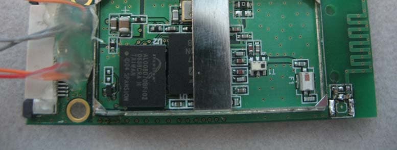
Click to zoom
Application Details
- Equipment Class
- DSS - Part 15 Spread Spectrum Transmitter
- Date of Grant
- Aug 13, 2007
- Application Purpose
- Original Equipment
- Date of Application
- Aug 13, 2007
- Equipment Note
- Bluetooth Module
- Frequency Range
- 2402.00000000 - 2480.00000000
- Country
- Taiwan
Documents & Files
Document Text
Text extracted from the exhibit documents filed with the FCC. Open a document above to read the original.
Users Manual
1 Bluetooth module Model Number: MP220 Doc version: 1.0 Customer: Date: July 11, 2006 USER MANUAL 2 I. Hardware operation introduction 1.1 Description The Bluetooth module MP220 is adopted CSR BlueCore 4 External ship solution. Which includes an 8Mbit Flash memory, used with CSR Bluetooth stack, provides a fully compliant Bluetooth system to v2.0 + EDR of the specification for data and voice communications. Features z Fully Qualified Bluetooth v2.0+EDR z Enhanced Data Rate (EDR) compliant with v2.0.E.2 of specification for both 2Mbps and 3Mbps modulation modes z Full speed USB v1.1 interface supports OHCI and UHCI host interfaces. Compliant with USB v2.0 z UART interface with programmable baud rate up to 3Mbaud with USB and an optional bypass mode z Support for 8Mbit External Flash z RoHS compliant z Bluetooth Class 2 RF output z 2.4GHz~2.483GHZ ISM band z Bluetooth stack runs on-chip in a variety of configurations, includes Standard HCI (UART or USB), Fully embedded to RFCOMM, or customized builds with embedded application code. 3 1.2 Specification Product Name Bluetooth Module Model Number MP220 Standard Bluetooth v2.0+EDR Frequency Band 2.4GHz ~ 2.4835GHz unlicensed ISM band Modulation Method GFSK for 1Mbps; Π/4-DQPSK for 2Mbps; 8-DPSK for 3Mbps Spread Spectrum FHSS (Frequency Hopping Spread Spectrum) Transfer rates (Max) Max UART baud rates of 3Mbps RF Output Power 0.01 mW/MHz Antenna PCB Antenna with 1.23dBi peak gain Stand by 10m 0.6mA 20m 0.9mA 30m 0.9mA Paring 15mA Power Consumption * Reconnect 50mA DC power DC 3.3V Dimension 48.5 x 19.5 mm Operating Temperature 0 ~ +60°C Storage Temperature -10 ~ +70°C Humidity 5 ~ 90% (non-condensing) * The values are measured when MP220 attaches to the scanner. 4 II. Software operation introduction BlueSoleil is a Windows-based software from IVT that allows your Bluetooth® enabled desktop or notebook computer to wirelessly connect to other Bluetooth enabled devices. BlueSoleil allows MS Windows users to wirelessly access a wide variety of Bluetooth enabled digital devices, such as cameras, mobile phones, headsets, printers, and GPS receivers. You can also form networks and exchange data with other Bluetooth enabled computers or PDAs. Platforms supported by BlueSoleil include: Windows 2000 and XP. 1.1 Bluetooth Functions In order to connect and share services via Bluetooth wireless technology, two devices must support the same Bluetooth Profile(s) as well as opposite device roles (i.e., one must be the server, and the other must be the client). Bluetooth enabled devices often support multiple profiles, and if involved in multiple connections, can perform different device roles simultaneously. BlueSoleil supports the following Bluetooth functions (Profiles) in the following device roles: Bluetooth Functions (Profiles) Client Server AV Headphone* √ √ Basic Image Profile √ √ Dial-Up Networking √ Fax √ File Transfer √ √ Headset* √ √ Human Interface Device √ LAN Access √ √ Object Push √ √ Personal Area Networking √ √ Printer √ 5 Serial Port √ √ Synchronization √ √ 1.2 Main Window Note: For more complete information about the Main Window (including the icon meanings) as well as information about the Service Window and BlueSoleil menus, please refer to Chapter 4. By default, BlueSoleil starts with the Main Window open. Use the Main Window to perform your primary connection operations. The Main Window displays the local device (red ball) as well as the remote devices detected in range. Different icons distinguish different types of remote devices. At the top of the Main Window are Service Buttons. After you search for the services supported by a remote device, the supported services of the selected device will be highlighted. Local Device — Basic Operations: • Hover your mouse over the red ball to display the local device's Bluetooth name and address. • Click on the red ball to start or stop searching for Bluetooth devices in range. • Right-click on the red ball to display a pop-up menu of related operations (e.g., General Inquiry, My Services, Security, etc.). Remote Devices — Icon Meanings • White — Idle. The normal state of the device. • Yellow—Selected. You have selected the device. • Green — Connected. The device is connected to your local device. Remote Devices — Operations • Single-click to select. • Double-click to search for the services supported by the device. • Right-click to display a pop-up menu of related operations (e.g., Refresh Devices, Pair Devices, Connect, etc.). Services — Icon Meanings • White — Idle. The normal state. • Yellow — Available. The service is available on the selected device. 6 • Green — Connected. The service is active in a connection with the remote device. Services — Operations • Hover your mouse over the service icon to display the name of the service. • Single-click on the service icon to connect. • Right-click on the service icon to display a pop-up menu of related operations. 7 Basic Operations 1.3 Install the Software IMPORTANT! If you have any Bluetooth software previously installed on your computer, you must completely remove it first! 1. Insert the BlueSoleil software installation CD into the CD drive of your computer. 2. Use My Computer or Windows Explorer to access your CD drive. In the CD, click on SETUP.EXE. 3. Follow the directions on your screen to install the software. 4. As prompted, when software installation is complete, restart your computer. 1.4 Start BlueSoleil 1. Start BlueSoleil. Click on the BlueSoleil icon on your desktop, or go to Start | Programs | IVT BlueSoleil | BlueSoleil. Note: BlueSoleil will detect each insertion or removal of the USB adapter. Alternatively, you can start BlueSoleil before plugging in the USB adapter. 2. The very first time you use BlueSoleil, the Welcome to Bluetooth screen will appear. Assign your Windows system a name and device type, to be shown to other Bluetooth enabled devices. In most cases, you should leave the security setting checked. Click OK. 1.5 Chec…
Text truncated - open the document above for the full version.
Cover Letter(s)
RF_734_00, Issue 1 Modular Approval Request FCC (per DA 00-1407) FCC ID: HLEMP220 Items to be covered Answer from applicant 1. The modular transmitter must have its own RF shielding. Yes 2. The modular transmitter must have buffered modulation/data inputs (if such inputs are provided) to ensure that the module will comply with Part 15 requirements under conditions of excessive data rates or over-modulation. Yes 3. The modular transmitter must have its own power supply regulation. Yes 4. The modular transmitter must comply with the antenna requirements of Section 15.203 and 15.204(c). The antenna must either be permanently attached or employ a “unique” antenna coupler (at all connections between the module and the antenna, including the cable).. Yes 5. The modular transmitter must be tested in a stand-alone configuration, i.e., the module must not be inside another device during testing. This is intended to demonstrate that the module is capable of complying with Part 15 emission limits regardless of the device into which it is eventually installed. Yes 6. The modular transmitter must be labeled with its own FCC ID number, and, if the FCC ID is not visible when the module is installed inside another device, then the outside of the device into which the module is installed must also display a label referring to the enclosed module. This exterior label can use wording such as the following: “Contains Transmitter Module FCC ID: XYZMODEL1” or “Contains FCC ID: XYZMODEL1.” Any similar wording that expresses the same meaning may be used. The Grantee may either provide such a label, an example of which must be included in the application for equipment authorization, or, must provide adequate instructions along with the module which explain this requirement. In the latter case, a copy of these instructions must be included in the application for equipment authorization. Contains Transmitter Module FCC ID: HLEMP220 7. The modular transmitter must comply with any specific rule or operating requirements applicable to the transmitter and the manufacturer must provide adequate instructions along with the module to explain any such requirements. A copy of these instructions must be included in the application for equipment authorization. For example, there are very strict operational and timing requirements that must be met before a transmitter is authorized for operation under Section 15.231. For instance, data transmission is prohibited, except for operation under Section 15.231(e), in which case there are separate field strength level and timing requirements. Compliance with these requirements must be assured. Yes 8. The modular transmitter must comply with any applicable RF exposure requirements. For example, FCC Rules in Sections 2.1091, 2.1093 and specific Sections of Part 15, including 15.319(i), 15.407(f), 15.253(f) and 15.255(g), require that Unlicensed PCS, UNII and millimeter wave devices perform routine environmental evaluation for RF Exposure to demonstrate compliance. In addition, spread spectrum transmitters operating under Section 15.247 are required to address RF Exposure compliance in accordance with Section 15.247(b)(4). Modular transmitters approved under other Sections of Part 15, when necessary, may also need to address certain RF Exposure concerns, typically by providing specific installation and operating instructions for users, installers and other interested parties to ensure compliance. Yes Note: If compliance with one or more of the numbered requirements, listed above, cannot be demonstrated, it may be possible to obtain a “Limited Modular Approval” (LMA). Name and surname of applicant (or authorized representative): Annie Yuan ; IA Dept. Specialist RF_734_00, Issue 1 Date: ___2007-08-10_ Signature:
External Photos
Project No.: 0705070 Page 2 of 4 Neutron Engineering Inc. 0705070 0705070 Project No.: 0705070 Page 2 of 4 Neutron Engineering Inc. 0705070 0705070 Project No.: 0705070 Page 3 of 4 Neutron Engineering Inc. 0705070 0705070
ID Label/Location Info
FCC ID: HLEMP220
Internal Photos
Project No.: 0705070 Page 2 of 4 Neutron Engineering Inc. 0705070 0705070 Project No.: 0705070 Page 2 of 4 Neutron Engineering Inc. 0705070 0705070 Project No.: 0705070 Page 3 of 4 Neutron Engineering Inc. 0705070 0705070 Project No.: 0705070 Page 3 of 4 Neutron Engineering Inc. 0705070 0705070 Project No.: 0705070 Page 4 of 4 Neutron Engineering Inc. 0705070
Test Report
Report No.: NEI-FCCP-1-0705070A Page 2 of 64 Neutron Engineering Inc. Declaration Neutron represents to the client that testing is done in accordance with standard procedures as applicable and that test instruments used has been calibrated with the standards traceable to National Measurement Laboratory (NML) of R.O.C., or National Institute of Standards and Technology (NIST) of U.S.A. Neutron's reports apply only to the specific samples tested under conditions. It is manufacture’s responsibility to ensure that additional production units of this model are manufactured with the identical electrical and mechanical components. Neutronshall have no liability for any declarations, inferences o r generalizations drawn by the client or others from Neutron issued reports. Neutron’s reports must not be used by the client to claim product endorsement by the authorities or any agency of the Government. This report is the confidential property of the client. As a mutual protection to the clients, the public and Neutron-self, extracts from the test report shall not be reproduced except in full with Neutron’s authorized written approval. Neutron’s laboratory quality assurance procedures are in compliance with the ISO Guide 17025 requirements, and accredited by the conformity assessment authorities listed in this test report. Limitation For the use of the authority's logo is limited unless the Test Standard(s)/Scope(s)/Item(s) mentioned in this test report is (are) included in the conformity assessment authorities acceptance respective. Report No.: NEI-FCCP-1-0705070A Page 3 of 64 Neutron Engineering Inc. Table of Contents Page 1 . CERTIFICATION 6 2 . SUMMARY OF TEST RESULTS 7 2.1 TEST FACILITY 8 2.2 MEASUREMENT UNCERTAINTY 8 3 . GENERAL INFORMATION 9 3.1 GENERAL DESCRIPTION OF EUT 9 3.2 DESCRIPTION OF TEST MODES 11 3.3 TABLE OF PARAMETERS OF TEXT SOFTWARE SETTING 11 3.4 BLOCK DIGRAM SHOWING THE CONFIGURATION OF SYSTEM TESTED 12 3.5 DESCRIPTION OF SUPPORT UNITS 13 4 . EMC EMISSION TEST 14 4.1 CONDUCTED EMISSION MEASUREMENT 14 4.1.1 POWER LINE CONDUCTED EMISSION LIMITS 14 4.1.2 MEASUREMENT INSTRUMENTS LIST AND SETTING 14 4.1.3 TEST PROCEDURE 15 4.1.4 DEVIATION FROM TEST STANDARD 15 4.1.5 TEST SETUP 15 4.1.6 EUT OPERATING CONDITIONS 16 4.2 RADIATED EMISSION MEASUREMENT 17 4.2.1 RADIATED EMISSION LIMITS 17 4.2.2 MEASUREMENT INSTRUMENTS LIST ANS SETTING 18 4.2.3 TEST PROCEDURE 19 4.2.4 DEVIATION FROM TEST STANDARD 19 4.2.5 TEST SETUP 20 4.2.6 EUT OPERATING CONDITIONS 20 4.2.7 TEST RESULTS (BETWEEN30 – 1000 MHZ) 21 4.2.8 TEST RESULTS (ABOVE 1000 MHZ) 23 4.2.9 TEST RESULTS (RESTRICTED BANDS REQUIREMENTS) 35 5 . NUMBER OF HOPPING CHANNEL 38 5.1 APPLIED PROCEDURES / LIMIT 38 5.1.1 MEASUREMENT INSTRUMENTS LIST AND SETTING 38 5.1.2 TEST PROCEDURE 38 5.1.3 DEVIATION FROM STANDARD 38 5.1.4 TEST SETUP 38 5.1.5 EUT OPERATION CONDITIONS 38 5.1.6 TEST RESULTS 39 Report No.: NEI-FCCP-1-0705070A Page 4 of 64 Neutron Engineering Inc. Table of Contents Page 6 . AVERAGE TIME OF OCCUPANCY 40 6.1 APPLIED PROCEDURES / LIMIT 40 6.1.1 MEASUREMENT INSTRUMENTS LIST 40 6.1.2 TEST PROCEDURE 40 6.1.3 DEVIATION FROM STANDARD 40 6.1.4 TEST SETUP 41 6.1.5 EUT OPERATION CONDITIONS 41 6.1.6 TEST RESULTS 42 7 . HOPPING CHANNEL SEPARATION MEASUREMENT 48 7.1 APPLIED PROCEDURES / LIMIT 48 7.1.1 MEASUREMENT INSTRUMENTS LIST AND SETTING 48 7.1.2 TEST PROCEDURE 48 7.1.3 DEVIATION FROM STANDARD 48 7.1.4 TEST SETUP 48 7.1.5 EUT OPERATION CONDITIONS 48 7.1.6 TEST RESULTS 49 8 . BANDWITH TEST 51 8.1 APPLIED PROCEDURES / LIMIT 51 8.1.1 MEASUREMENT INSTRUMENTS LIST AND SETTING 51 8.1.2 TEST PROCEDURE 51 8.1.3 DEVIATION FROM STANDARD 51 8.1.4 TEST SETUP 51 8.1.5 EUT OPERATION CONDITIONS 51 8.1.6 TEST RESULTS 52 9 . PEAK OUTPUT POWER TEST 54 9.1 APPLIED PROCEDURES / LIMIT 54 9.1.1 MEASUREMENT INSTRUMENTS LIST AND SETTING 54 9.1.2 TEST PROCEDURE 54 9.1.3 DEVIATION FROM STANDARD 54 9.1.4 TEST SETUP 54 9.1.5 EUT OPERATION CONDITIONS 54 9.1.6 TEST RESULTS 55 10 . ANTENNA CONDUCTED SPURIOUS EMISSION 57 10.1 APPLIED PROCEDURES / LIMIT 57 10.1.1 MEASUREMENT INSTRUMENTS LIST AND SETTING 57 10.1.2 TEST PROCEDURE 57 10.1.3 DEVIATION FROM STANDARD 57 10.1.4 TEST SETUP 58 10.1.5 EUT OPERATION CONDITIONS 58 Report No.: NEI-FCCP-1-0705070A Page 5 of 64 Neutron Engineering Inc. Table of Contents Page 10.1.6 TEST RESULTS 59 11 . RF EXPOSURE TEST 61 11.1 APPLIED PROCEDURES / LIMIT 61 11.1.1 MEASUREMENT INSTRUMENTS LIST 61 11.1.2 MPE CALCULATION METHOD 61 11.1.3 DEVIATION FROM STANDARD 62 11.1.4 TEST SETUP 62 11.1.5 EUT OPERATION CONDITIONS 62 11.1.6 TEST RESULTS 63 12 . EUT TEST PHOTO 64 Report No.: NEI-FCCP-1-0705070A Page 6 of 64 Neutron Engineering Inc. 1. CERTIFICATION Equipment : Bluetooth Module Trade Name : unitech Model Name : MP220 A p p l i c a n t : unitech electronics co., ltd. T e s t I t e m : ENGINEERING SAMPLE Standards : FCC Part15, Subpart C(15.247) / ANCI C63.4 : 2003 The above equipment has been tested and found compliance with the requirement of the relative standards by Neutron Engineering Inc. EMC Laboratory. The test data, data evaluation, and equipment configuration contained in our test report (Ref No. NEI-FCCP-1-0705070A) were obtained utilizing the test procedures, test instruments, test sites that has been accredited by the Authority of NVLAP and CNLA according to the ISO-17025 quality assessment standard and technical standard(s). Report No.: NEI-FCCP-1-0705070A Page 7 of 64 Neutron Engineering Inc. 2. SUMMARY OF TEST RESULTS Test procedures according to the technical standards: FCC Part15 (15.247) , Subpart C Standard Section Test Item Judgment Remark 15.207 Conducted Emission PASS 15.247 (c) Antenna conducted Spurious EmissionPASS 15.247 (a)(1) Hopping Channel Separation PASS 15.247 (b)(1) Peak Output Power PASS 15.247 (c) Radiated Spurious Emission PASS 15.247 (b)(1) Number of Hopping Frequency PASS 15.247 (a)(1) Dwell Time PASS 15.205 Restricted Bands PASS 15.203 Antenna Requirement PASS 1.1307 1.1310 2.1091 2.1093 RF Exposure Complian…
Text truncated - open the document above for the full version.
Test Setup Photos
Report No.: NEI-FCCP-1-0705070A Page 64 of 64 Neutron Engineering Inc. 12. EUT TEST PHOTO Radiated Measurement Photos 0705070A 0705070A Report No.: NEI-FCCP-1-0705070A Page 64 of 64 Neutron Engineering Inc. 12. EUT TEST PHOTO Radiated Measurement Photos 0705070A 0705070A
Contact Information
Applicant
Ben Chiang
Technical Contact
Neutron Engineering, Inc.Annie Yuan
[email protected]+86-769-87082000
B1, No. 37, Lane 365, YuangGuang St., · Taipei · Taiwan
Test Firm
BTL Inc.Andy Yeh
Technical Specifications
| # | Rule Parts | Frequency Range | Power Output |
|---|---|---|---|
| 1 | 15C | 2.40 GHz - 2.48 GHz | 3.00 mW |
Other Applications from Unitech Electronics Co., Ltd.
HLERG768PU
Jul 29, 2026RG768 Plus gun grip
Equipment Class
DSS - Part 15 Spread Spectrum TransmitterHLEEA530BWNWU
Feb 16, 2026Rugged Handheld Computer
Equipment Class
DTS - Digital Transmission SystemHLEEA530BWNW
Feb 16, 2026Rugged Handheld Computer
Equipment Class
6XD - 15E 6 GHz Low Power Indoor Client
HLERP300BU
Nov 24, 2025RP300 UHF RFID Mobile Reader
Equipment Class
DSS - Part 15 Spread Spectrum Transmitter
HLERM300PU
Sep 01, 2024RM300 Plus UHF RFID Reader Module
Equipment Class
DSS - Part 15 Spread Spectrum Transmitter