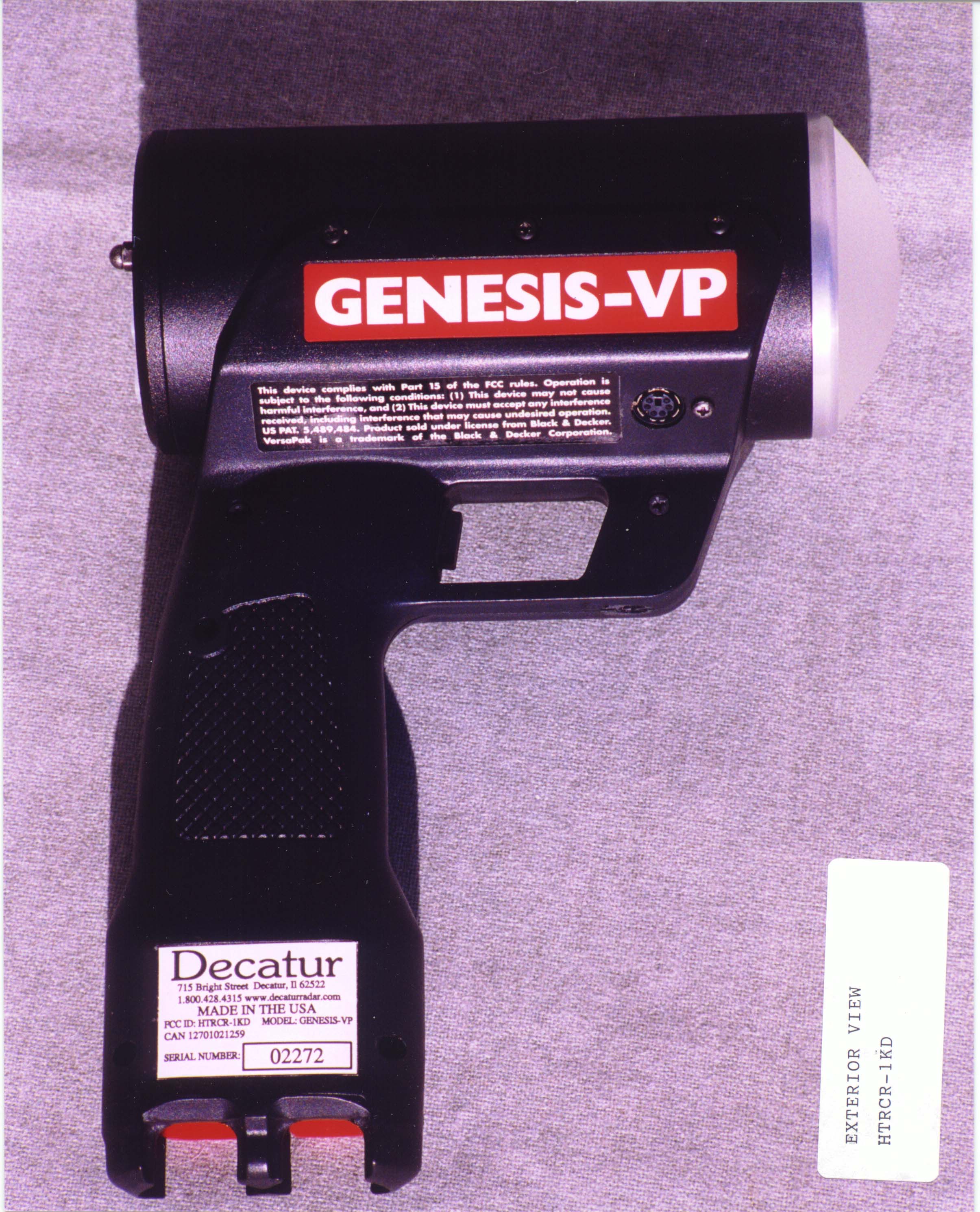
HTRCR-1KDTraffic Safety Radar
Decatur Electronics
Click to zoom
Application Details
- Equipment Class
- FDS - Part 15 Field Disturbance Sensor
- Date of Grant
- Feb 27, 2000
- Application Purpose
- Original Equipment
- Date of Application
- Dec 20, 1999
- Equipment Note
- Traffic Safety Radar
- Frequency Range
- 24075.00000000 - 24175.00000000
- Company
- Decatur Electronics
- Country
- United States
Documents & Files
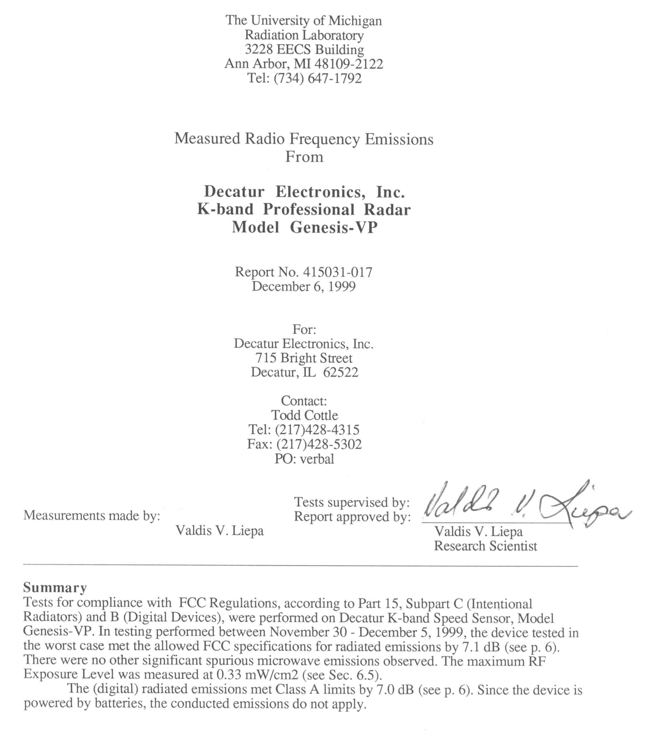
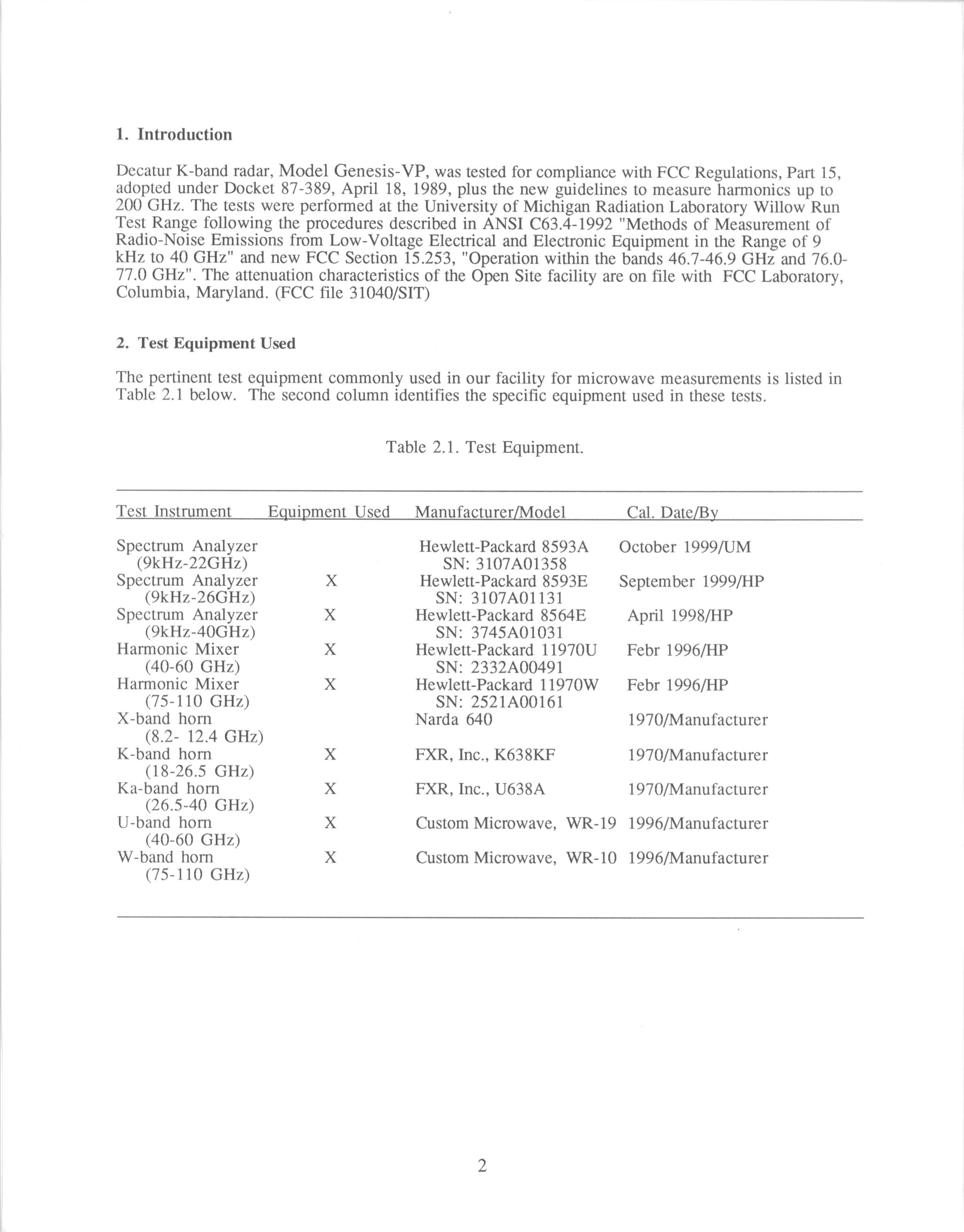
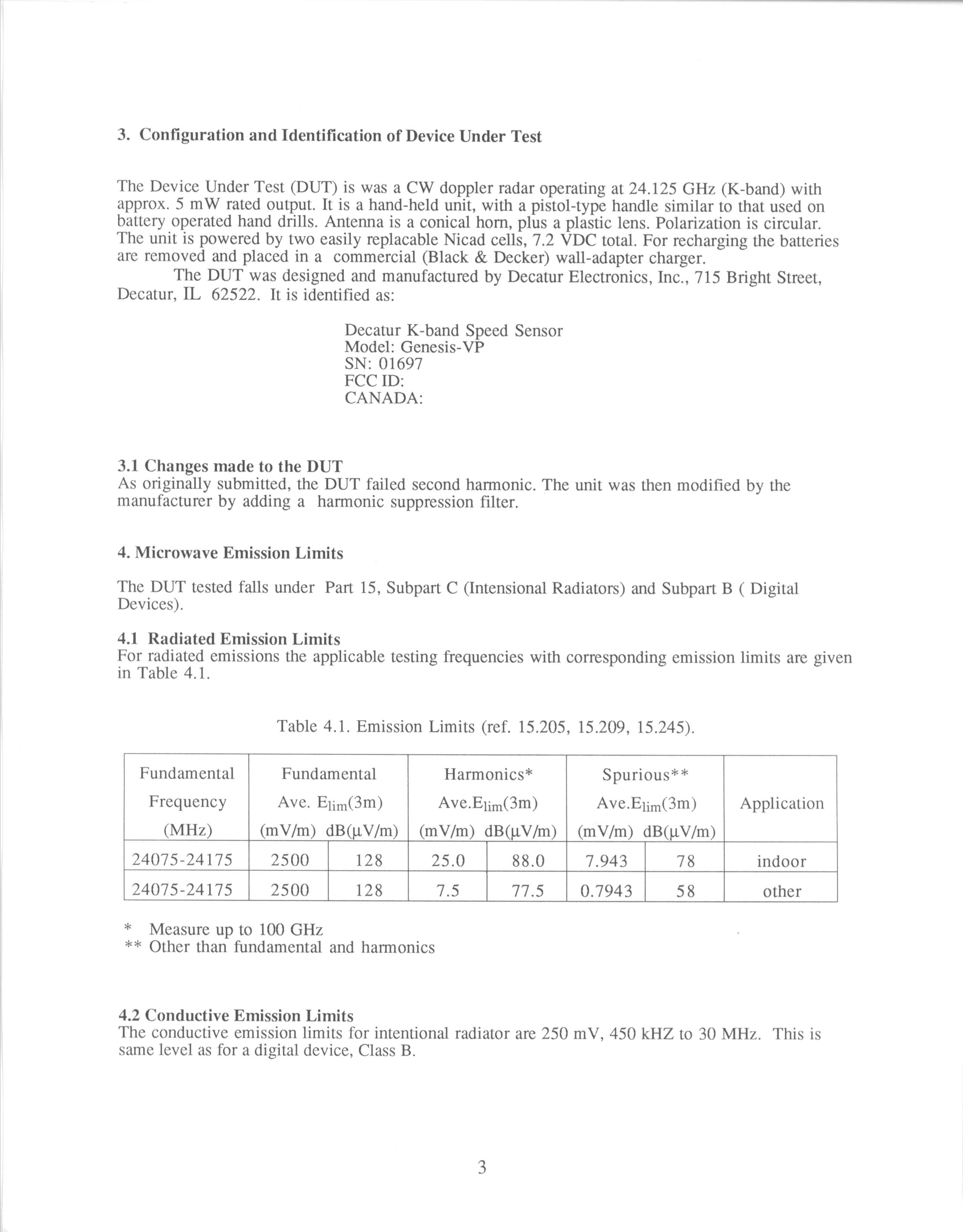
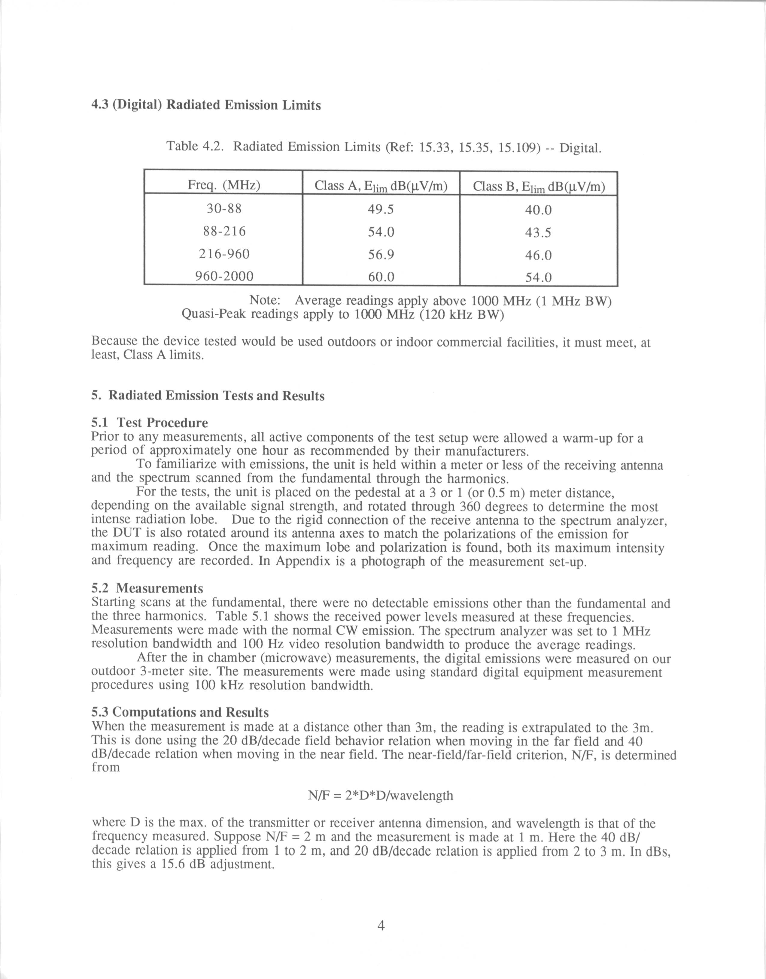
Document Text
Text extracted from the exhibit documents filed with the FCC. Open a document above to read the original.
Users Manual
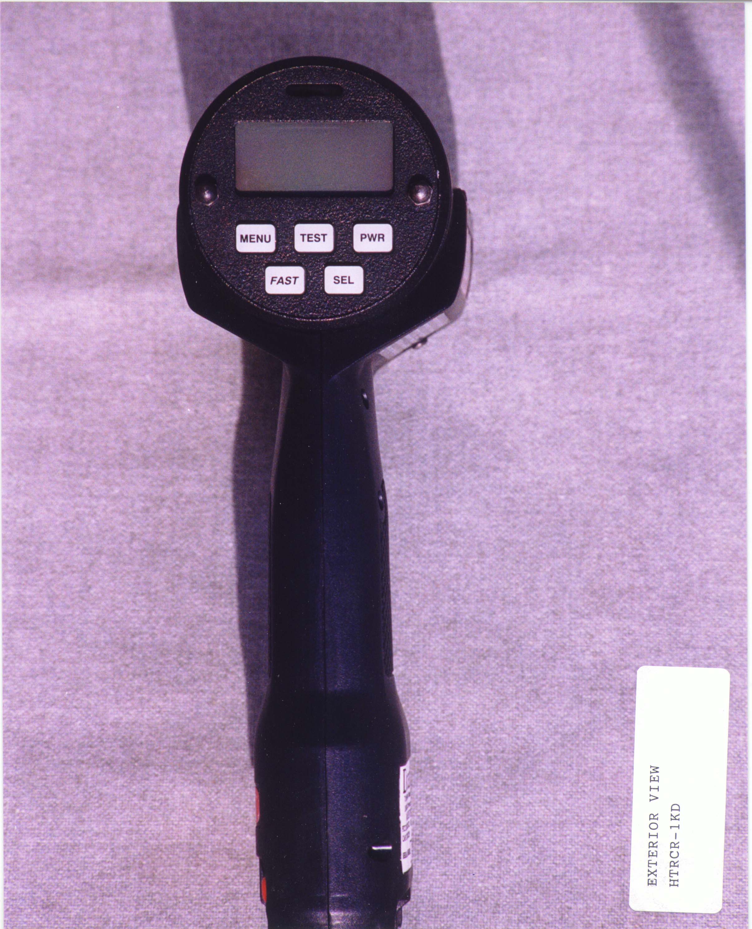
1 GENESIS-VP™: User’s Manual Decatur Electronics, Inc. GENESIS-VP™ User’s Manual 715 Bright Street Decatur, IL 62522 USA/Canada: 1.800.428.4315 FAX: 1.217.428.5302 INTL: 1.217.428.4315 www.decaturradar.com Revised December 28, 1999 GENESIS-VP™: User’s Manual 2 INSERT Genesis-VP Instructions for use of the target direction tracking mode. Your Genesis-VP speed radar pistol may have had target direction tracking mode added to its program software during product configuration. The following explanations and instructions apply to target direction tracking mode with the Genesis-VP. You can determine whether or not target direction tracking mode is on or off by going into the secondary menu and toggling to the “dir” window. If it says “on” then, of course, target direction tracking mode is on. If it says “off” then, of course, it is off and the unit will function as a standard Genesis-VP. When operating the Genesis-VP in target direction tracking mode: 1.The Genesis-VP will lock onto the target that has the strongest return signal and also attempt to determine that target’s direction of travel. The target’s speed will be displayed in the left window and, if successful in determining target direction, the target direction will be displayed in the right window. A “t” for “towards” will be displayed for a target moving toward the Genesis-VP and an “A” for “away” will be displayed for a target moving away from the Genesis-VP. If the Genesis-VP is not successful in determining the target’s direction of travel then neither a “t” or an “A” will be displayed. 2.When you lock a target the locked target speed will be displayed in the right window. The right display will alternately flash this locked speed and the direction of the locked target (if the direction was determined). 3.If you use the faster target mode in conjunction with the target direction tracking mode then this rule of thumb applies... When the right window is not being used by another function then a “t” for “toward” or an “A” for “away” will be displayed in the right window to indicate the target’s direction of travel. 3 GENESIS-VP™: User’s Manual Table of Contents 1.Quick Start Instructions ........................................... 4 2.Controls ..................................................................... 9 3.Displays ................................................................... 14 4.Modes of Operation ................................................ 16 5.Serial Communications Option ............................. 18 6.Field Tests ................................................................ 18 7.Care, Cleaning, and Storage .................................. 21 8.Limitations to Doppler RADAR .............................. 21 9.Warranty .................................................................. 25 10.Service Return Procedure ...................................... 26 Appendix 1, Specifications .............................................. 27 Appendix 2, FDA Notice ................................................... 28 Appendix 3, FCC/ISC Documents ................................... 30 Appendix 4, Case Law ...................................................... 31 Copyright © 1998, Decatur Electronics, Inc. GENESIS-VP™: User’s Manual 4 Figure 1: Inserting Batteries 1. Quick Start Instructions 1.1Insert VersaPak™ batteries Remove VersaPak™ batteries from their package and charge them (please refer to VersaPak™ instruction sheet). When the VersaPak™ batteries are charged, insert them into the base of the handle grip as shown until you hear them snap into place. 1.2Turn on the power Push the power button. The Genesis-VP™ will do a display test and beep and then blank the speed windows. 5 GENESIS-VP™: User’s Manual 1.3Set Menu Options Primary menu You may use the factory default settings listed below or you may select your own settings. To select your own settings, press and hold the MENU button. You will see “bL” (for back light) in the left window and “OFF” in the right window. If you wish to change this to “ON,” then simply press the SEL (select) button. (The SEL button is used to toggle/cycle through all available values for a given parameter.) Release and press the MENU button again to move to the next category and repeat the process. When finished, release the buttons and your new settings will be in effect. The unit will “remember” the last settings when turned off and will power up with the last set values in each category. See section 2.3 on Menus for other settings. Factory default settings: bL (back light) .......................... = on Aud (audio volume) .................. = 3 SEN (sensitivity) ...................... = 5 SLh (squelch) ........................... = on Figure 2: Primary Menu GENESIS-VP™: User’s Manual 6 Secondary menu You may use the factory default settings listed below or you may select your own settings. To select your own settings, press and hold the SEL (select) button and then press the MENU button. You will see “Prt” (for communication port) in the left window and a “O” (for none) in the right window. If you wish to change this to an other mode of serial port communication, then simply release and press the SEL (select) button. (The SEL button is used to toggle/cycle through all available values for a given parameter.) Press the MENU button again to move to the next category and repeat the process. When finished, release the buttons and your new settings will be in effect. See section 2.3 on Menus for other settings. Factory default settings: Prt (communication port) ......... 0 = No serial communication FSt (fastest vehicle style) .......... 1 = Fastest-toggle tSt (test) .................................... off You are now ready to measure the speed of targets. Figure 3: Secondary Menu Master Reset To reset all parameters (except the “tSt” setting) to their default values, press and hold the SEL (select) button while pressing the PWR (power) button when turning the unit ON. The un…
Text truncated - open the document above for the full version.
Cover Letter(s)
December 21, 1999 Federal Communications Commission Equipment Approval Services P.O. Box 358315 Pittsburgh, PA 15251-5315 Re: Certification for Genesis VP Directional Traffic Safety Radar, Model CR-1KD FCC ID: HTRCR-1KD Please find the enclosed application materials for Certification under Part 15 for Genesis VP Directional Traffic Safety Radar, Model CR-1KD. The device has been tested and meets Part 15 requirements. The transitional provisions of Section 15.37 are not required. Decatur Electronics, Inc. has previously been granted a FCC manufacturer code of 2R4 and a applicant/grantee code of HTR. Pursuant to 47 CFR 0.459 we request that portions of the subject application be held confidential. The items to be held confidential are (1) Exhibit F Schematic Diagrams The market for this device is a very competitive one, with a small profit margin. Decatur Electronics has spent appreciable time and finances in developing this product, and having the subject information available to “competitors” will negate the advantage we have achieved in developing this product. It will create financial hardships for our company if we do not protect our design. If there are any questions regarding this request please contact me at the address below or call (217)-428- 4315. Decatur Electronics looks forward to receiving FCC approval on this device. Cordially, Todd Cottle Design Engineer Enclosures: Form 731 with $1075.00 payment plus relevant materials
Operational Description
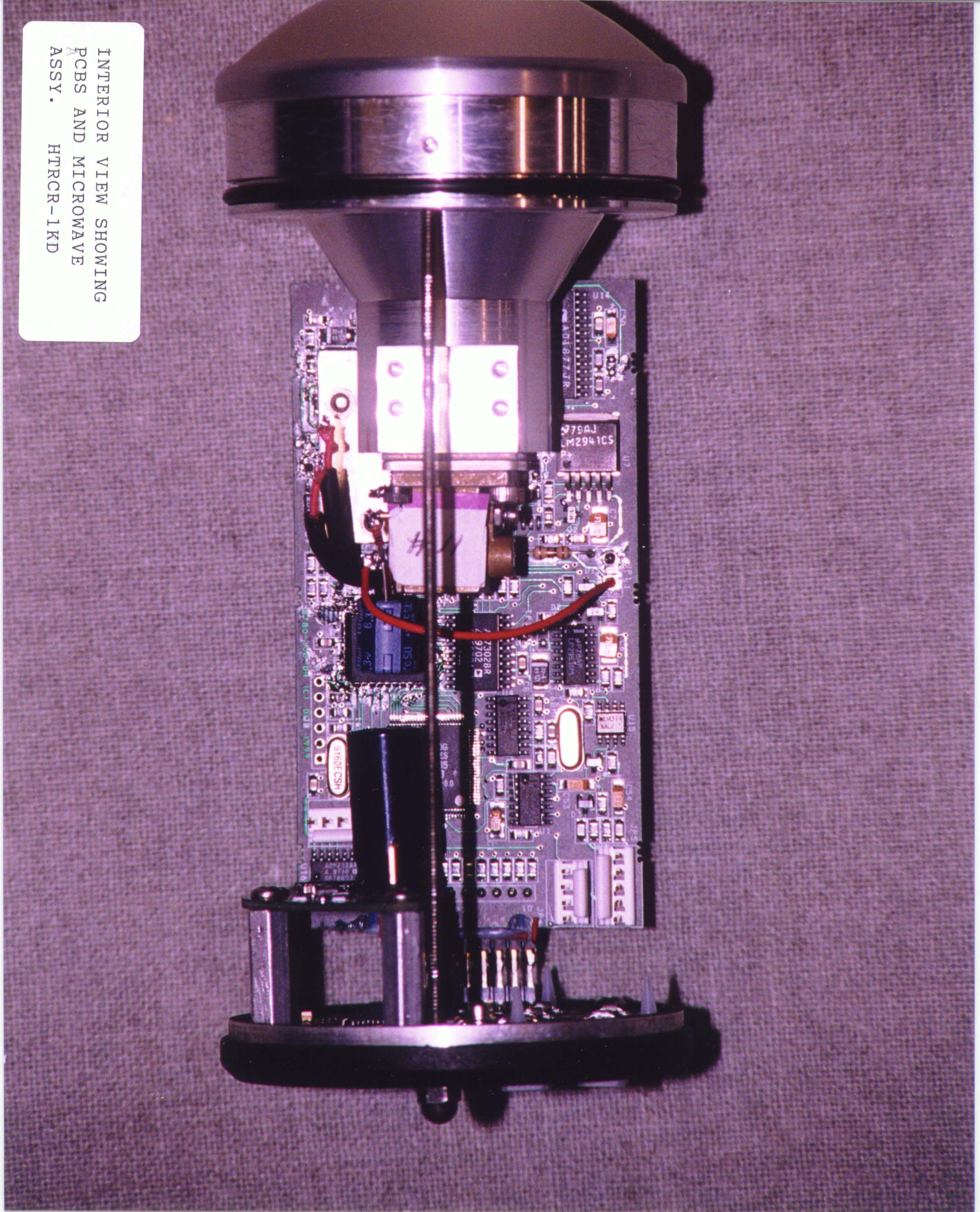
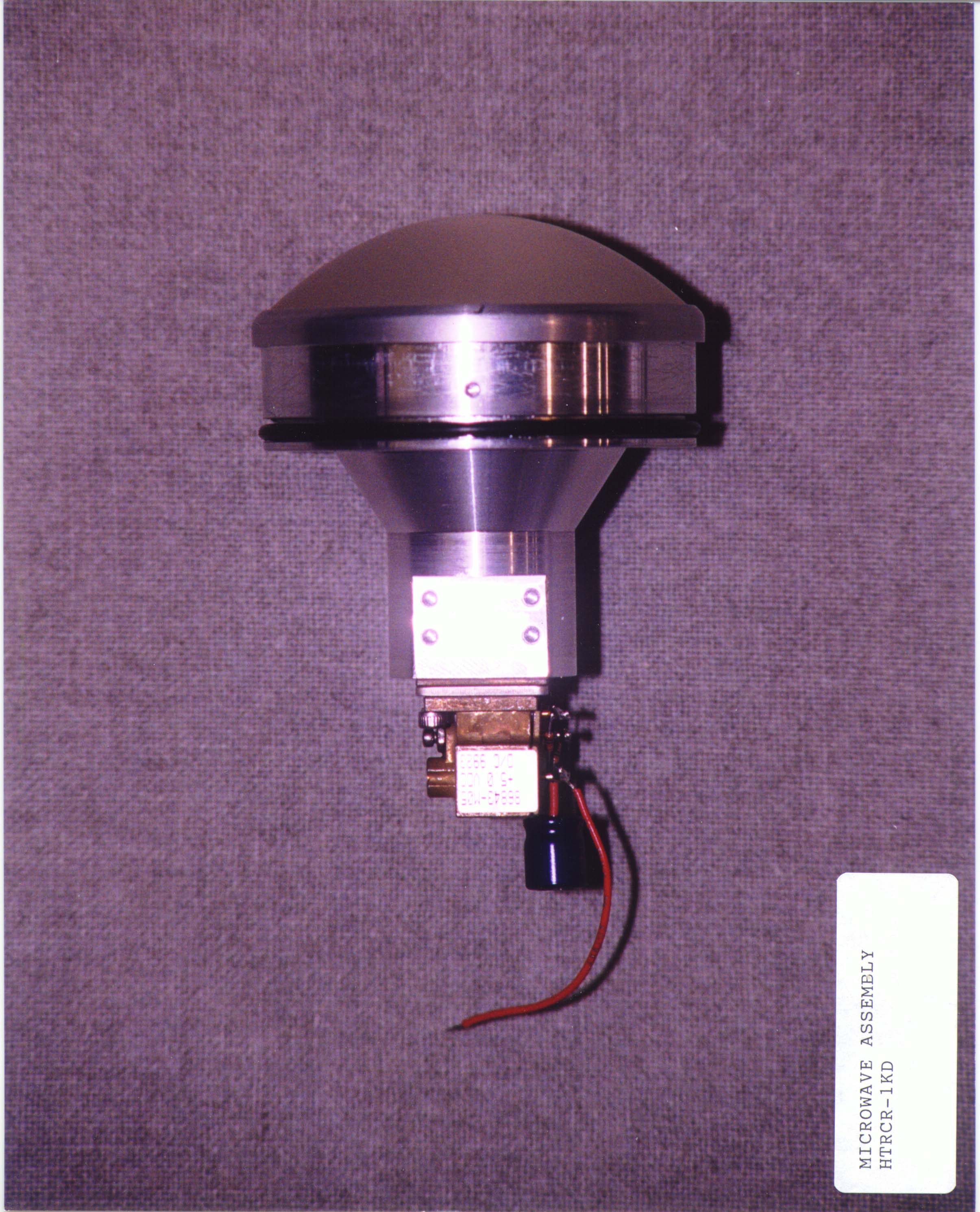
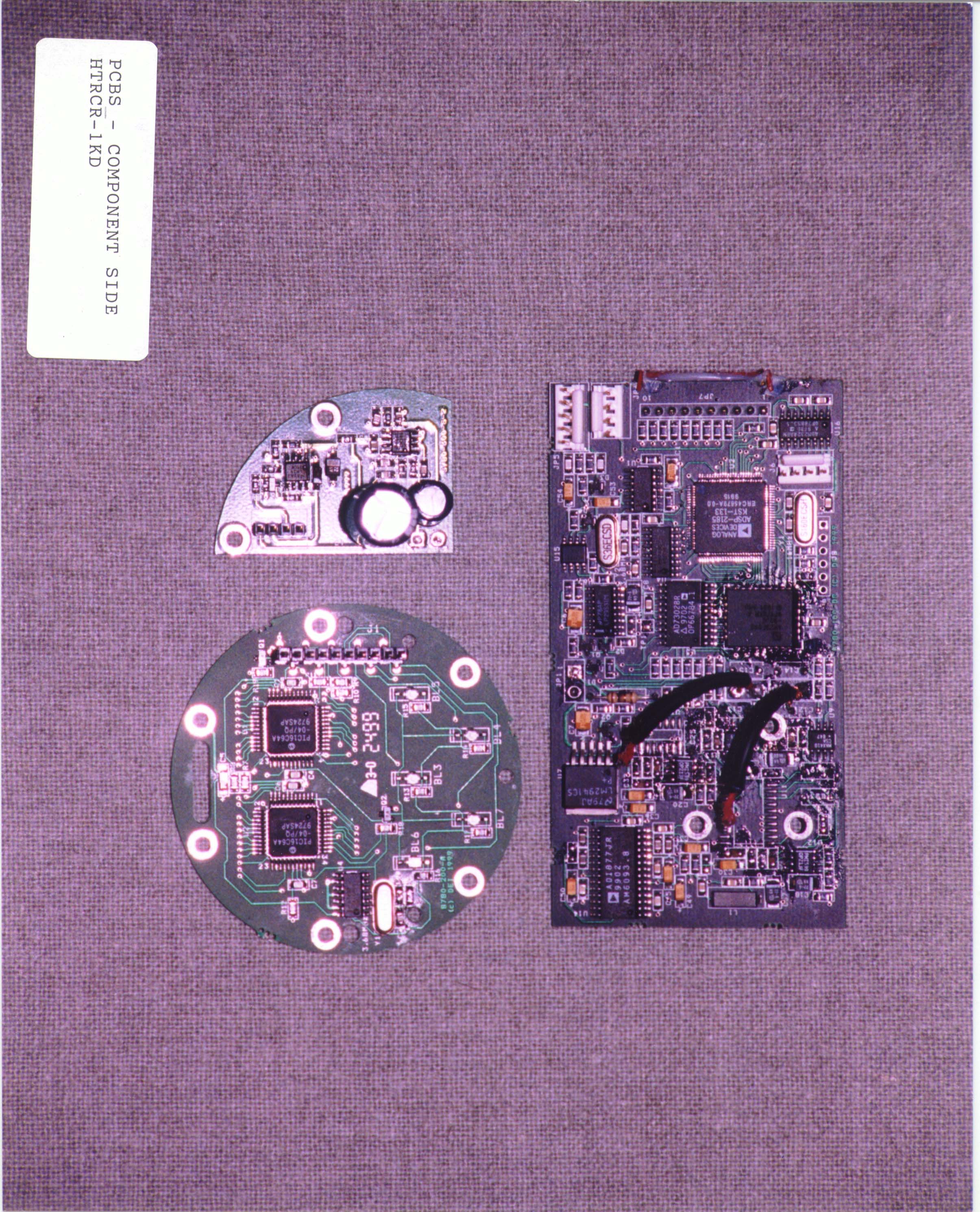
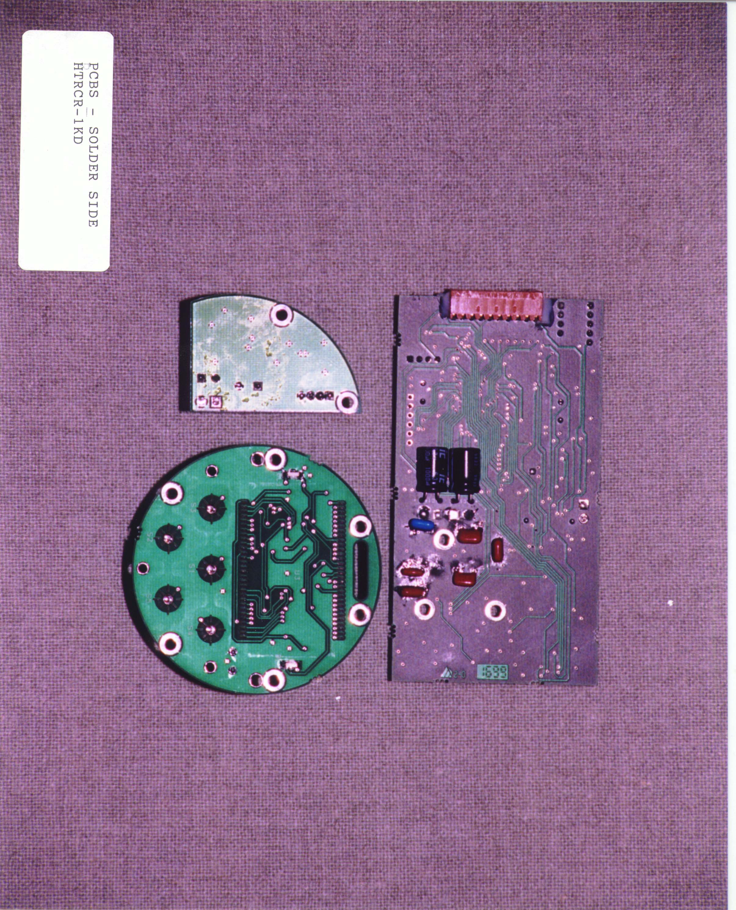
Genesis VP Theory of Operation FCC ID: HTRCR-1KD When the operator presses the power switch it momentarily activates the logic regulator. After reset, the DSP processor boot loads its program and asserts a line keeping the logic regulator in the "on" state. The processor continuously monitors the keypad and trigger switch. When the trigger is pulled the processor activates the TX enable line turning the Gunn regulator on. Upon receiving power the Gunn oscillator section of the microwave transceiver generates a 5mW 25.125 GHz (nominal) NON signal. Some of the microwave power provides LO pumping for the receiver diodes and the horn/lens antenna radiates the remainder. If the radiated energy happens to strike a moving object, part of the energy will be reflected back towards the antenna. The frequency of the reflected energy is Doppler shifted proportional to its speed. This reflected energy is mixed at the receiver diodes extracting the Doppler shift. The placement of the receiver diodes is such that by apply appropriate DSP algorithms the direction of the object may be determined. The low level Doppler signal are amplified by the preamplifiers and digitized by a stereo A/D converter at a rate of 31.250 kHz. The DSP analyses the digital stream to determine if a valid target is present. If so the speed is displayed via the display board. It also generates an audio signal proportional to the signals Doppler shift via a D/A converter (U5). A digital code may also be sent out the serial port via the RS-232 converter (U16). If the radar gun is operated in the vicinity of a radio transmitter, the energy may interfere with the accuracy of the gun. The RFI Detect circuit (U15) monitors for such situations and disables the display when such conditions exist. The processor also monitors a 368Hz signal to verify it accuracy.
Contact Information
Applicant
Kimble J Smith(Senior Electrical Engineer)
Technical Contact
Decatur ElectronicsTodd Cottle
[email protected]217-428-4315
715 Bright · Decatur, Illinois · United States
Test Firm
University of MichiganValdis Liepa
Technical Specifications
| # | Rule Parts | Frequency Range | Power Output | Tolerance |
|---|---|---|---|---|
| 1 | 15C | 24.07 GHz - 24.18 GHz | - | % |
Other Applications from Decatur Electronics

HTR-SI3
Aug 11, 2013Traffic/Speed Radar
Equipment Class
FDS - Part 15 Field Disturbance Sensor
HTRSI-3L
Feb 26, 2013Low profile directional radar unit
Equipment Class
FDS - Part 15 Field Disturbance Sensor
HTR-HR1
May 07, 2005Hand Remote
Equipment Class
DSC - Part 15 Security/Remote Control TransmitterHTRCR-1K
Jul 13, 1997Sports Radar Gun
Equipment Class
FDS - Part 15 Field Disturbance SensorHTR355KA
Jun 15, 1995TNB - Licensed Non-Broadcast Station Transmitter
Equipment Class
TNB - Licensed Non-Broadcast Station Transmitter