HWF-MBTH120BT-DH
Mustek Systems Inc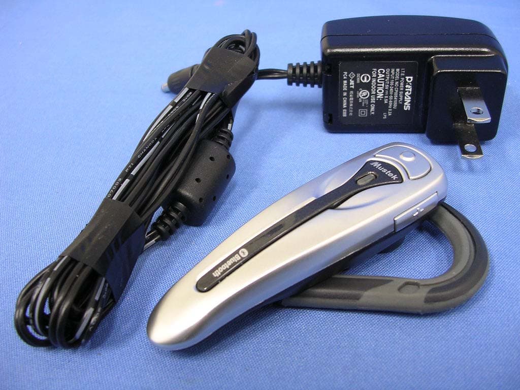
Click to zoom
Application Details
- Equipment Class
- DSS - Part 15 Spread Spectrum Transmitter
- Date of Grant
- Mar 23, 2005
- Application Purpose
- Original Equipment
- Date of Application
- Mar 23, 2005
- Equipment Note
- BT-DH
- Frequency Range
- 2402.00000000 - 2480.00000000
- Company
- Mustek Systems Inc
- Country
- Taiwan
Documents & Files
Document Text
Text extracted from the exhibit documents filed with the FCC. Open a document above to read the original.
Users Manual
Quick Guide Headset E N F I R U G R P L T U D K S W P T N L E S I T F R D E T C Model No.: MBT-H120 FCC ID: HWF-MBTH120 This device complies with part 15 of the FCC rules. Operation is subject to the following two conditions: (1) This device may not cause harmful interference. (2) This device must accept any interference received, including interference that may cause undesired operation. Any changes or modifi cations not expressly approved by the party responsible for com- pliance could void the authority to operate equipment. Tested To Comply With FCC Standards FOR HOME OR OFFICE USE BLUETOOTH HEADSET GETTING STARTEDBLUETOOTH HEADSET GETTING STARTED 3 BLUETOOTH HEADSET GETTING STARTEDBLUETOOTH HEADSET GETTING STARTED E N 1 2 3 4 5 6 7 8 Identifying the Parts 1. Volume Up / Pairing Button 2. Power / Talking Button 3. Volume Down 4. Indicator LED Red : Power Off Blue : Power On Red+Blue : Pairing mode 5. Earhook 6. Earphone 7. Microphone 8. DC-IN jack BLUETOOTH HEADSET GETTING STARTEDBLUETOOTH HEADSET GETTING STARTED 4 Charging the Battery First time use: Please charge the built-in Li-ion bat- tery for 24 hours before the initial use. Low battery: When the battery is low, the indicator LED will fl ash red. Please charge the battery for approximately 2.5 hours. How to charge: 1. Connect one end of the supplied AC Adapter (5V/0.5A) to the DC IN jack on the headset and the other end to the wall outlet. The indicator LED will light red when charging. After fully charging the battery, the indicator LED will light out. Remove the AC Adapter from the DC IN jack of the headset and the wall outlet. Wearing the Headset To wear on your right ear: Reverse the earhook to change its direction, and then follow the steps above to wear it on your right ear. (Figure 1) (Figure 2) 5 BLUETOOTH HEADSET GETTING STARTEDBLUETOOTH HEADSET GETTING STARTED Wearing the Headset E N You can wear the headset on either ear with the reversible earhook. To wear on your left ear: Wear the headset vertically on your left ear. (Please refer to Figure 1) Rotate the headset toward the rear of your ear and point the microphone toward your mouth. (Please refer to Figure 2) 6 BLUETOOTH HEADSET GETTING STARTEDBLUETOOTH HEADSET GETTING STARTED To power your headset on: Press the Power button for approxi- mately 2 seconds until the indicator LED starts to fl ash blue. Then you can start to operate your headset. To power your headset off: Press the Power button for approxi- mately 2 seconds until the indicator LED starts to fl ash red. Once the indicator LED stops fl ashing, the power is OFF. Powering the Headset On or Off 7 BLUETOOTH HEADSET GETTING STARTEDBLUETOOTH HEADSET GETTING STARTED E N Pairing with a Bluetooth Phone and blue alternately, and enters the pairing mode. 3. Search for Bluetooth devices by following the phone’s operating instruction. 4. Select “MBT-H120” from the searched devices list and confi rm it. Enter the passkey “1234” and confi rm it. After fi nishing the pairing process, the indicator LED will fl ash blue. ( Notes: 1) The operable range without obstructions is up to 10 meters (approximately 33 feet) between your headset and the Bluetooth devices. 2) Your headset can save the pairing infor- mation of up to 8 phones, but connect to only one phone at a time. Before operating your headset with a Bluetooth phone, you must execute “Pairing” process to create a link between the devices. To pair with a Bluetooth phone, please follow the instruction below: Ensure the headset is ON and enters the standby mode with fl ashing blue LED once rapidly every 3 seconds. ( Note: When powered on, the headset will attempt to connect to an available Bluetooth device. Please press the Power button to switch to the standby mode. ) 2. Press the Volume Up button for approximately 4 seconds until the indicator LED starts to fl ash red 8 BLUETOOTH HEADSET GETTING STARTEDBLUETOOTH HEADSET GETTING STARTED If you have entered the passkey without previously pairing with another phone, the phone will be the “default phone” for your headset. If you want to use another Bluetooth phone with your headset, please switch the headset off, then disconnect it from the previous phone. Next, pair with another phone once restarted as described in page 7. ) Pairing with a Bluetooth Phone-continue 9 BLUETOOTH HEADSET GETTING STARTEDBLUETOOTH HEADSET GETTING STARTED E N Call Functions the voice tag through your headset’s microphone. 4) After recognizing the correct voice tag, the phone number will be dialed automatically. ( Note: This feature is only available with a phone that supports the ‘Voice Dialing’ function. For details, please refer to your phone’s user guide. ) To redial the last call: 1. Press the Volume Down button for approximately 2 seconds when no call is in progress. To reject a call: 1. Press the Power button for approximately 2 seconds to reject an incoming call. To answer or end a call: When receiving a call, you will hear a ring tone through the headset’s ear- phone. Press the Power/Talk button to answer or end a call. To make a call: There are two ways to make a call: 1. Using your phone’s keypad: Press the Number button you want to call in your phone’s keypad to make a call. 2. Using the “Voice Dialing” function through your headset: 1) Record “Voice Tags” in your phone address book in advance. 2) Ensure this function is ON. 3) Press the Talk button, then say 1010 BLUETOOTH HEADSET GETTING STARTEDBLUETOOTH HEADSET GETTING STARTED While plugging in the charger: Headset Indicator LED Indicator LEDHeadset Light Red Charging Light OutFull Charge While unplugging the charger: Indicator LEDHeadset Flash Red Low Battery Flash Red Light Out Power Off Flash BluePower On Flash Red and Blue Alternately Pairing Mode Flash Blue LED once rapidly every 3 seconds Signal Available (Standby Mode) Flash Blue LED twice rapidly every 3 seconds Connecting Flash Blue LED 3 times rapidly every 3 seconds Connected Flash Blue LED 4 times rapidly every 3 s…
Text truncated - open the document above for the full version.
External Photos
Report No: 052H038-F-R02-T Page: 50 of 55 Version:1.0 Attachement ¾ EUT Photograph (1) EUT Photo (2) EUT Photo
ID Label/Location Info
FCC ID.: HWF-MBTH120 No.25, R&D Road II, Science-Based Industrial Park, Hsin-Chu, Taiwan, R.O.C. FCC ID and DoC Label The FCC ID and DoC Label will be placed on the equipment as shown in the photograph below. BT-DH Model No.: MBT-H120 FCC ID : HWF-MBTH120 This device complies with Part 15 of the FCC Rules. Operation is subject to the following two conditions: (1) this device may not cause harmful interference and (2) this device must accept any interference received, including interference that may cause undesired operation. S/N: Made in Taiwan Trade name: BT-DH Model number.: HWF-MBTH120
ID Label/Location Info
FCC ID.: HWF-MBTH120 No.25, R&D Road II, Science-Based Industrial Park, Hsin-Chu, Taiwan, R.O.C. FCC ID and DoC Label The FCC ID and DoC Label will be placed on the equipment as shown in the photograph below. BT-DH Model No.: MBT-H120 FCC ID : HWF-MBTH120 This device complies with Part 15 of the FCC Rules. Operation is subject to the following two conditions: (1) this device may not cause harmful interference and (2) this device must accept any interference received, including interference that may cause undesired operation. S/N: Made in Taiwan Trade name: BT-DH Model number.: HWF-MBTH120
Internal Photos
Report No: 052H038-F-R02-T Page: 51 of 55 Version:1.0 (3) EUT Photo Report No: 052H038-F-R02-T Page: 52 of 55 Version:1.0 (4) EUT Photo Report No: 052H038-F-R02-T Page: 53 of 55 Version:1.0 (5) EUT Photo (6) EUT Photo Report No: 052H038-F-R02-T Page: 54 of 55 Version:1.0 (7) EUT Photo Report No: 052H038-F-R02-T Page: 55 of 55 Version:1.0 (8) EUT Photo (9) EUT Photo
Operational Description
Report No: 052H038-F-R02-T Page: 7 of 55 Version:1.0 1.2. Operational Description The EUT is an BT-DH with 79 channels. This device provides wireless technology that revolutionizes personal connectivity. It is the solution for the seamless integration of Bluetooth technology into personal computer enabling short-range wireless connections between desktop/laptop computers, Bluetooth-enabled peripherals (printers, faxes,....), portable handheld devices, and connectivity to the Internet.
Test Report
Report No: 052H038-F-R02-T Page: 1 of 57 Version:1.0 Test Report Product Name:BT-DH Model No. :MBT-H120 FCC ID. :HWF-MBTH120 Applicant :Mustek Systems Inc. Address :No.25, R&D Road II, Science-Based Industrial Park, Hsin-Chu, Taiwan, R.O.C. Date of Receipt:2005/02/18 Issued Date :2005/03/03 Report No. :052H038-F-R02-T The test results relate only to the samples tested. The test report shall not be reproduced except in full without the written approval of QuieTek Corporation. Report No: 052H038-F-R02-T Page: 2 of 57 Version:1.0 Test Report Certification Issued Date : 2005/03/03 Report No. : 052H038-F-R02-T Product Name : BT-DH Applicant : Mustek Systems Inc. Address : No.25, R&D Road II, Science-Based Industrial Park, Hsin-Chu, Taiwan, R.O.C. Manufacturer : Mustek Systems Inc. Model No. : MBT-H120 FCC ID. : HWF-MBTH120 Rated Voltage : AC 120 V / 60 Hz EUT Voltage : Battery 3.6V Trade Name : Mustek Applicable Standard : FCC CFR Title 47 Part 15 Subpart C Section 15.247: 2003 Test Result : Complied The test results relate only to the samples tested. The test report shall not be reproduced except in full without the written approval of QuieTek Corporation. Documented By : ( Sandy Chuang ) Tested By : ( Louis Hsu ) Approved By : ( James Chang ) Report No: 052H038-F-R02-T Page: 3 of 57 Version:1.0 TABLE OF CONTENTS Description Page 1. General Information.................................................................................................................5 1.1. EUT Description..........................................................................................................................5 1.2. Operational Description.............................................................................................................7 1.3. Test Mode....................................................................................................................................8 1.4. Tested System Details................................................................................................................9 1.5. Configuration of tested System................................................................................................9 1.6. EUT Exercise Software............................................................................................................10 1.7. Test Facility................................................................................................................................11 2. Conducted Emission.............................................................................................................13 2.1. Test Equipment.........................................................................................................................13 2.2. Test Setup..................................................................................................................................13 2.3. Limits...........................................................................................................................................14 2.4. Test Procedure..........................................................................................................................14 2.5. Test Specification......................................................................................................................14 2.6. Test Result.................................................................................................................................15 2.7. Test Photo..................................................................................................................................17 3. Peak Power Output................................................................................................................18 3.1. Test Equipment.........................................................................................................................18 3.2. Test Setup..................................................................................................................................18 3.3. Limits...........................................................................................................................................18 3.4. Test Specification......................................................................................................................18 3.5. Test Result.................................................................................................................................19 4. Radiated Emission.................................................................................................................20 4.1. Test Equipment.........................................................................................................................20 4.2. Test Setup..................................................................................................................................20 4.3. Limits...........................................................................................................................................21 4.4. Test Procedure..........................................................................................................................21 4.5. Test Specification......................................................................................................................21 4.6. Test Result.................................................................................................................................22 4.7. Test Photo..................................................................................................................................34 5. Band Edge................................................................................................................................36 5.1. Test Equipment.........................................................................................................................36 5.2. Test Setup............................…
Text truncated - open the document above for the full version.
Test Setup Photos
Report No: 052H038-F-R02-T Page: 17 of 55 Version:1.0 2.7. Test Photo Test Mode : Charge Mode Description: Front View of Conducted Emission Test Setup Test Mode : Charge Mode Description: Back View of Conducted Emission Test Setup Report No: 052H038-F-R02-T Page: 34 of 55 Version:1.0 4.7. Test Photo Test Mode : Mode 1: Transmit Description: Front View of Radiated Emission Test Setup Test Mode : Mode 1: Transmit Description: Back View of Radiated Emission Test Setup Report No: 052H038-F-R02-T Page: 35 of 55 Version:1.0 Test Mode : Mode 1: Transmit Description: Front View of Radiated Emission Test Setup (Horn)
Contact Information
Applicant
Miller Hsieh(Electronics Engineer)
886-3577-9373Fax: 886-3578-4139
Test Firm
QuieTek CorporationWarren Lin
Technical Specifications
| # | Rule Parts | Frequency Range | Power Output |
|---|---|---|---|
| 1 | 15C | 2.40 GHz - 2.48 GHz | 1.00 mW |
Other Applications from Mustek Systems Inc
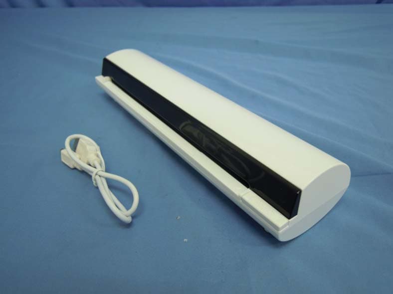
HWFHALO675
Sep 29, 2013Wireless Scanner
Equipment Class
DTS - Digital Transmission System
HWF839692
Jul 24, 2013Wireless Scanner
Equipment Class
DTS - Digital Transmission System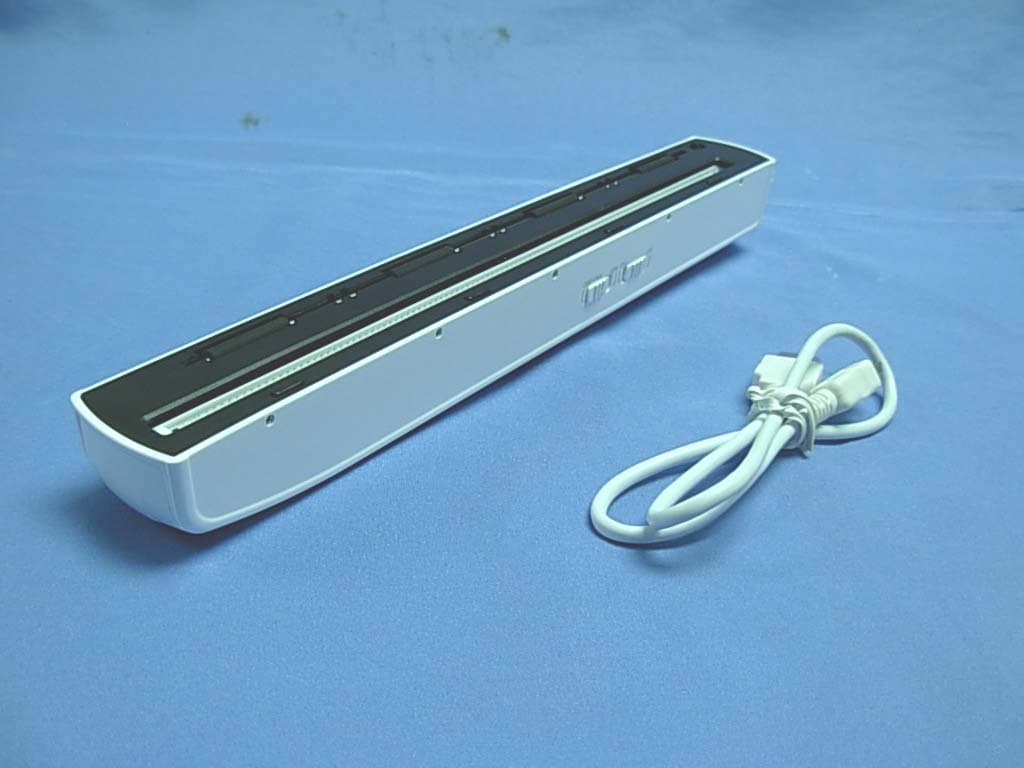
HWFH410W
Jun 03, 2013Wireless Handy Scanner
Equipment Class
DTS - Digital Transmission System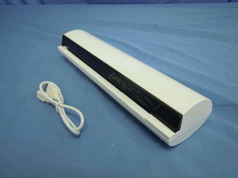
HWFS400W
Dec 26, 2012Scanner
Equipment Class
DTS - Digital Transmission System
HWF-MBTS120
Dec 07, 2005Bluetooth
Equipment Class
DSS - Part 15 Spread Spectrum Transmitter