I4S-LN1263Column Array Powered Speaker System
Peavey Electronics Corporation
Click to zoom
Application Details
- Equipment Class
- DSS - Part 15 Spread Spectrum Transmitter
- Date of Grant
- Feb 23, 2020
- Application Purpose
- Original Equipment
- Date of Application
- Feb 23, 2020
- Equipment Note
- Column Array Powered Speaker System
- Frequency Range
- 2402.00000000 - 2480.00000000
- Country
- United States
Documents & Files
Document Text
Text extracted from the exhibit documents filed with the FCC. Open a document above to read the original.
Users Manual
1 www.peavey.com LN™1263 Column ARRAY Specifications 2 Features and specifications are subject to change without notice. Peavey Electronics Corporation • 711 A Street • Meridian, MS 39301 (601) 483-5365 • FAX (601) 486-1278 • www.peavey.com © 2015 EX000030 FCC/ICES Compliancy Statement This device complies with Part 15 of the FCC rules and Industry Canada license-exempt RSS Standard(s). Operation is subject to the following two conditions: (1) this device may not cause harmful interference, and (2) this device must accept any interference received, that may cause undesired operation. Le présent appareil est conforme aux CNR d’lndustrie Canada applicables aux appareils radio exempts de licence. L’exploitation est autorisée aux deux conditions suivantes: (1) I’appareil ne doit pas produire de brouillage, et (2) I’utilisateur de I’appareil doit accepter tout brouillage radioélectrique subi, même si le brouillage est susceptible d’en compromettre le fonctionnement. Warning: Changes or modifications to the equipment not approved by Peavey Electronics Corp. can void the user’s authority to use the equipment. Note – This equipment has been tested and found to comply with the limits for a Class B digital device, pursuant to Part 15 of the FCC /ISE Rules . These limits are designed to provide reasonable protection against harmful interference in a residential installation. This equipment generates, uses, and can radiate radio frequency energy and, if not installed and used in accordance with the instructions, may cause harmful interference to radio communications. However, there is no guarantee that interference will not occur in a particular installation. If this equipment does cause harmful interference to radio or television reception, which can be determined by turning the equipment off and on, the user is encouraged to try and correct the interference by one or more of the following measures. • Reorient or relocate the receiving antenna. • Increase the separation between the equipment and receiver. • Connect the equipment into an outlet on a circuit different from that to which the receiver is con- nected. • Consult the dealer or an experienced radio/TV technician for help. D FCC/IC Radiation Exposure Statement. This equipment complied with FCC/IC radiation exposure requirement. The device can be used in fixed/mobile(min20cm) exposure condition without restriction. 3 • Bluetooth audio control via iOS app • Bluetooth audio input for streaming music from any Bluetooth device • 6 Channel mixer • 4 Combi inputs with Guitar Channel selectability • 4 Onboard guitar channels • 1 1/4” Stereo input channel • 3.5 mm input • Professional and Simple modes • Stereo capable • Onboard LCD display • 7 EQ presets • 8 FX • Compressor per channel Description: The LN™1263 is a compact, powerful, lightweight and low profile portable column-array. Utilizing 1200 watts of potential maximum power, the unit contains 12 2.75” custom drivers for the mid-high column and a custom 12” driver for the subwoofer. Completely self contained, the unit has no visible cables in mono operation. Its clean design is well suited for applications where speakers should be heard and not seen. Coming in at 10lbs lighter than our nearest competitor, the LN1263 is extremely easy to carry: an entire PA system that can be moved by one person in one trip. The satellite speakers feature rugged aluminum housing and quick attachment design. The subwoofer is built from multi-ply birch, making it both durable and lightweight. Each satellite features a speaker stand and a twist lock speaker cable connection, allowing the satellite to be positioned remotely for applications where stereo configuration or additional coverage is desired. Modern DSP makes this unit extremely easy to use and operate. Featuring both an onboard LCD screen and remote con- trol via Bluetooth using a custom iOS application for control, the LN1263 is state of the art. In addition to conventional features such as EQ and Effects, the app includes Simple and Professional mode, allowing more advanced users complete control while simplifying features like compression for novice users. The onboard mixer features 4 combo inputs, each with the option of selecting a guitar input, making this the first column array designed specifically with the acoustic guitar performer in mind. Two additional media channels feature stereo 1/4” inputs and streaming audio Bluetooth in. This unique Bluetooth input can handle a separate device other than the one controlling the array. Features also include seven onboard EQ presets and eight onboard effects, with the ability to save and lock scenes along with an independent sub level control. Perfect for church, convention, DJ or club applications, the LN1263 offers the best-in-class feature-to-value and performance in the industry. LN™1263 Column Array Powered Speaker System Congratulations on purchasing the Peavey LN™1263 Column Array Powered Speaker System. This compact, portable and powerful system is a perfect solution for the weekend warrior, singer songwriter or DJ. FEATURES: ENGLISH Installation Note: This unit must have the following clearances from any combustible surface: top: 8", sides: 12", back: 12" • Independent sub level control • Mute and line indicators per channel • Mix out for additional units • Security lock • Save and store scene presets • Aluminum satellite chassis • Birch ply subwoofer • Satellite speaker carrying bag included • 1,200 Watts maximum power • 127 dB maximum SPL • Frequency response 35 Hz - 20 kHz 5 CN EN PANEL CONTROLS PANEL CONTROL LAYOUT 6 PANEL CONTROL DESCRIPTION PANEL CONTROL DESCRIPTION PANEL CONTROL DESCRIPTION 1. CH1-CH4 XLR COMBO INPUT XLR/6.35mmtrs mono balance input, you can connect to microphone and line input 2.CH1-CH4 SIGNAL/LIMITER INDICATION Indication ch1-ch4 input signal/limiter, signal is green , limiter is red 3. CH1-CH4 MIC/GTR/LINE SELECT SWITCH Those switches allow you to select the correct inpu…
Text truncated - open the document above for the full version.
External Photos
HVIN: LN1263 External photo HVIN: LN1263 HVIN: LN1263 HVIN: LN1263 HVIN: LN1263
ID Label/Location Info
This device complies with Part 15 of the FCC rules and Industry Canada license-exempt RSS Standard(s). Operation is subject to the following two conditions: (1) this device may not cause harmful interference, and (2) this device must accept any interference received, that may cause undesired operation. This Class B digital apparatus complies with Canadian ICES-0003. Le présent appareil est conforme aux CNR d’lndustrie Canada applicables aux appareils radio exempts de licence. L’exploitation est autorisée aux deux conditions suivantes: (1) I’appareil ne doit pas produire de brouillage, et (2) I’utilisateur de I’appareil doit accepter tout brouillage radioélectrique subi, même si le brouillage est susceptible d’en compromettre le fonctionnement. HVIN:HVIN:HVIN:HVIN:HVIN:HVIN:HVIN:HVIN:HVIN:HVIN:HVIN:HVIN: Label & Label Location (HVIN: LN1263)
Internal Photos
HVIN: LN1263 Internal photo HVIN: LN1263 BT Antenna BT Module HVIN: LN1263 HVIN: LN1263
Operational Description
Peavey Electronics Corp Declaration concerning Antenna Specification It is hereby declared that the product Model No.: LN1263 FCC ID: I4S-LN1263 fulfills the requirement in FCC test relating to the antenna type. The device specified above confirms to the FCC recommendations for PCB antenna type(s) described below: Model No. of antenna: ANT1 Type of antenna: PCB antenna Gain of the antenna: 0 dBi Frequency range: 2402-2480MHz The mounting of the antenna is fixed to the radio module and no other antenna should be used. Company name: Peavey Electronics Corp Address: 5022 Hartley Peavey Drive, City: Meridian MS. ZIP / Postal code: 39305 Country: United States Name: Larry Bernard Date: 2020-02-22 Signature:
RF Exposure Info
Dongguan Nore Testing Center Co., Ltd. Report No.: NTC1908014FV00-1 FCC ID: I4S-LN1263 RF EXPOSURE EVALUATION EUT Specification EUT Column Array Powered Speaker System Frequency band (Operating) WLAN: 2.412GHz ~ 2.462GHz WLAN: 5.18GHz ~ 5.32GHz / 5.50GHz ~ 5.70GHz WLAN: 5.745GHz ~ 5825GHz Others(Bluetooth: 2.402GHz ~ 2.480GHz) Device category Portable (<20cm separation) Mobile (>20cm separation) Others ___ Antenna diversity Single antenna Multiple antennas Tx diversity Rx diversity Tx/Rx diversity Max. output power 3.087 dBm (2.0356 mW) Antenna gain 0 dBi Evaluation applied MPE Evaluation SAR Evaluation Limits for Maximum Permissible Exposure (MPE) Frequency Range(MHz) Electric Field Strength(V/m) Magnetic Field Strength(A/m) Power Density(mW/cm 2 ) 300-1500 -- -- F/1500 1500-100000 -- -- 1 Dongguan Nore Testing Center Co., Ltd. Report No.: NTC1908014FV00-1 FCC ID: I4S-LN1263 Friis transmission formula: Pd=(Pout*G)\(4*pi*R 2 ) Where Pd= Power density in mW/cm 2 Pout=output power to antenna in Mw G= gain of antenna in linear scale Pi=3.1416 R= distance between observation point and center of the radiator in cm Pd the limit of MPE, 1mW/cm2. If we know the maximum gain of the antenna and total power input to the antenna, through the calculation, we will know the distance where the MPE limit is reached. Measurement Result Channel Gain Channel Frequency (MHz) Max Output power (dBm) Tolerance Max Tune-UP power (mW) Power density at 20cm (mW/ cm 2 ) Power density Limits (mW/cm 2 ) Test Mode: GFSK Low 0 2402 -2.323± 0.5 0.6572 0.0001 1 Middle 0 2441 1.351 ± 0.5 1.5314 0.0003 1 High 0 2480 3.087 ± 0.5 2.2840 0.0005 1 Test Mode: π/4-DQPSK Low 0 2402 -2.180± 0.5 0.6792 0.0001 1 Middle 0 2441 0.901 ± 0.5 1.3807 0.0003 1 High 0 2480 2.643 ± 0.5 2.0621 0.0004 1 Test Mode: 8DPSK Low 0 2402 -2.108± 0.5 0.6906 0.0001 1 Middle 0 2441 0.749 ± 0.5 1.3332 0.0003 1 High 0 2480 2.607 ± 0.5 2.0450 0.0004 1
Test Report
Dongguan Nore Testing Center Co., Ltd. Report No.: NTC1908014FV00 FCC ID: I4S-LN1263 Page 2 of 59 Table of Contents 1. GENERAL INFORMATION ................................................................................................ 5 1.1 PRODUCT DESCRIPTION FOR EQUIPMENT UNDER TEST ................................................................. 5 1.2 RELATED SUBMITTAL(S) / GRANT (S) ............................................................................................ 7 1.3 TEST METHODOLOGY .................................................................................................................. 7 1.4 EQUIPMENT MODIFICATIONS ........................................................................................................ 7 1.5 SUPPORT DEVICE ....................................................................................................................... 7 1.6 TEST FACILITY AND LOCATION ..................................................................................................... 8 1.7 SUMMARY OF TEST RESULTS ....................................................................................................... 9 1.8 DEVIATIONS AND ABNORMALITIES FROM STANDARD CONDITIONS ................................................... 9 2. SYSTEM TEST CONFIGURATION .................................................................................. 10 2.1 EUT CONFIGURATION ............................................................................................................... 10 2.2 SPECIAL ACCESSORIES ............................................................................................................. 10 2.3 DESCRIPTION OF TEST MODES ................................................................................................... 10 2.4 EUT EXERCISE ......................................................................................................................... 10 3. CONDUCTED EMISSIONS TEST .................................................................................... 11 3.1 TEST SET-UP (BLOCK DIAGRAM OF CONFIGURATION) ................................................................ 11 3.2 TEST CONDITION ....................................................................................................................... 11 3.3 MEASUREMENT RESULTS .......................................................................................................... 11 4. RADIATED EMISSION TEST ........................................................................................... 14 4.1 TEST SET-UP (BLOCK DIAGRAM OF CONFIGURATION) ................................................................ 14 4.2 MEASUREMENT PROCEDURE ..................................................................................................... 15 4.3 LIMIT ........................................................................................................................................ 16 4.4 MEASUREMENT RESULTS ................................................................................................. 16 5. CHANNEL SEPARATION TEST ...................................................................................... 20 5.1 MEASUREMENT PROCEDURE ..................................................................................................... 20 5.2 TEST SET-UP (BLOCK DIAGRAM OF CONFIGURATION) ................................................................ 20 5.3 MEASUREMENT RESULTS .......................................................................................................... 20 6. 20DB BANDWIDTH .......................................................................................................... 26 6.1 MEASUREMENT PROCEDURE ..................................................................................................... 26 6.2 TEST SET-UP (BLOCK DIAGRAM OF CONFIGURATION) ................................................................ 26 6.3 MEASUREMENT RESULTS .......................................................................................................... 26 7. HOPPING CHANNEL NUMBER ...................................................................................... 32 7.1 MEASUREMENT PROCEDURE ..................................................................................................... 32 7.2 TEST SET-UP (BLOCK DIAGRAM OF CONFIGURATION) ................................................................ 32 7.3 MEASUREMENT RESULTS .......................................................................................................... 32 Dongguan Nore Testing Center Co., Ltd. Report No.: NTC1908014FV00 FCC ID: I4S-LN1263 Page 3 of 59 8. TIME OF OCCUPANCY (DWELL TIME) .......................................................................... 35 8.1 MEASUREMENT PROCEDURE ..................................................................................................... 35 8.2 MEASUREMENT RESULTS .......................................................................................................... 35 9. MAXIMUM PEAK OUTPUT POWER ............................................................................... 41 9.1 MEASUREMENT PROCEDURE ..................................................................................................... 41 9.2 MEASUREMENT RESULTS .......................................................................................................... 41 10. BAND EDGE .................................................................................................................. 47 10.1 MEASUREMENT PROCEDURE ................................................................................................... 47 10.2 LIMIT ...................................................................................................................................... 47 10.3 MEASUREMENT RESULTS ........................................................................................................ 4…
Text truncated - open the document above for the full version.
Test Setup Photos
HVIN: LN1263 Test photo Radiation Emission (30MHz-1GHz) Radiation Emission (Above 1GHz) HVIN: LN1263 Conducted Emission
Contact Information
Applicant
T.J Wang(Product Compliance Manager)
Test Firm
Dongguan NTC CO., Ltd.Jees Hong
[email protected]+86-769-22022444
Technical Specifications
| # | Rule Parts | Frequency Range | Power Output |
|---|---|---|---|
| 1 | 15C | 2.40 GHz - 2.48 GHz | 2.10 mW |
Other Applications from Peavey Electronics Corporation

I4S-MESSENGER
Sep 03, 2026Active BT Wireless Speaker & Portable Instrument Amplifier
Equipment Class
DSS - Part 15 Spread Spectrum Transmitter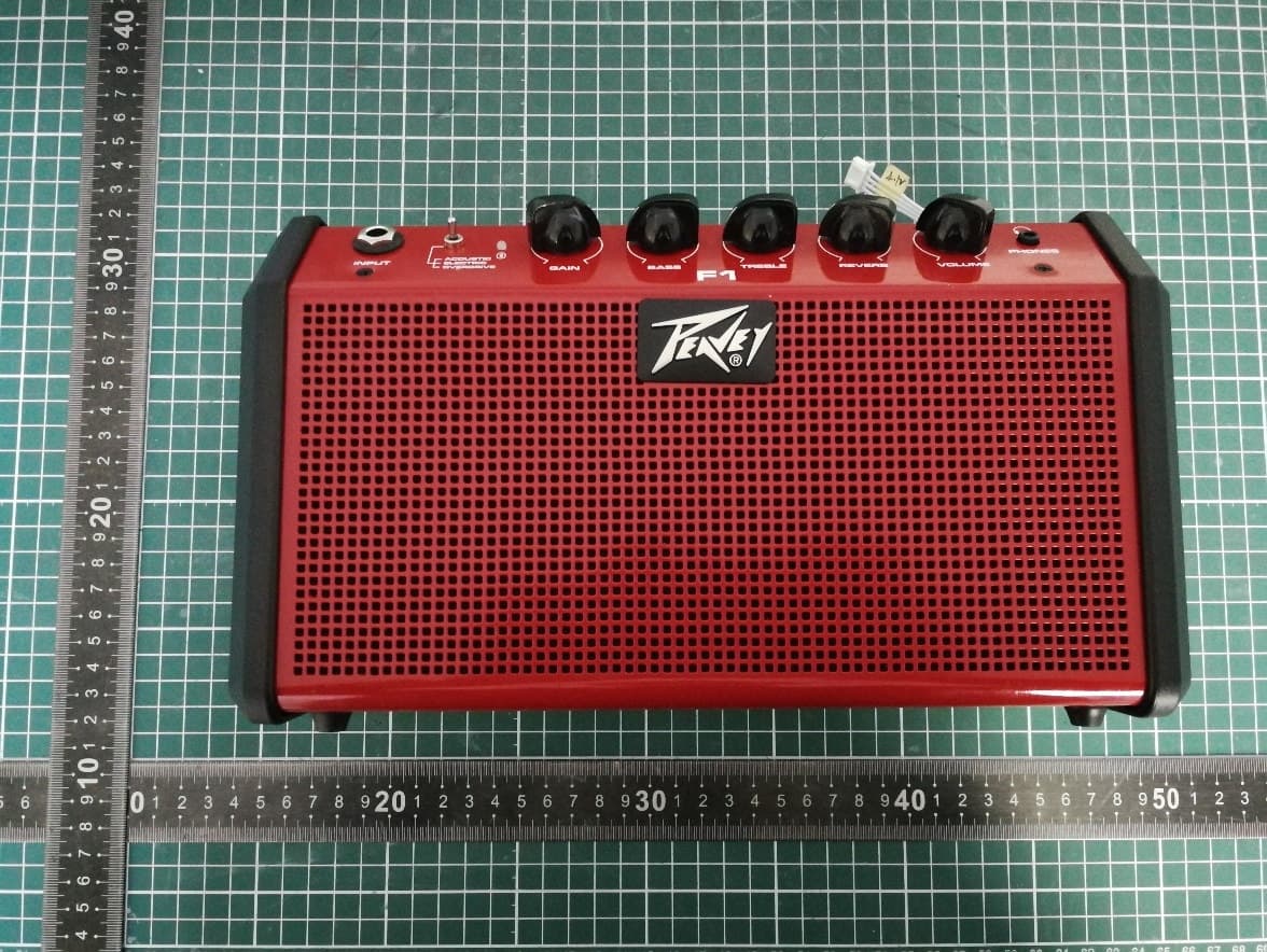
I4S-F1
Apr 24, 2026Active BT Wireless Speaker & Portable Instrument Amplifier
Equipment Class
DSS - Part 15 Spread Spectrum TransmitterI4S-SOLO
Apr 10, 2024Powered Speaker
Equipment Class
DSS - Part 15 Spread Spectrum Transmitter
I4S-AQ
Dec 18, 2022Powered Speaker
Equipment Class
DTS - Digital Transmission System
I4S-LN1063
Nov 19, 2020Column Array Powered Speaker System
Equipment Class
DSS - Part 15 Spread Spectrum Transmitter