I4S-PV6BTAudio Mixer
Peavey Electronics Corporation
Click to zoom
Application Details
- Equipment Class
- DSS - Part 15 Spread Spectrum Transmitter
- Date of Grant
- May 21, 2015
- Application Purpose
- Original Equipment
- Date of Application
- May 21, 2015
- Equipment Note
- Audio Mixer
- Frequency Range
- 2402.00000000 - 2480.00000000
- Country
- United States
Documents & Files
Document Text
Text extracted from the exhibit documents filed with the FCC. Open a document above to read the original.
Users Manual
www.peavey.com PV ® 6 • PV ® 6BT Compact Mixer Operating Manual FCC/ICES Compliancy Statement This device complies with Part 15 of the FCC rules and Industry Canada license-exempt RSS Standard(s). Operation is subject to the following two conditions: (1) this device may not cause harmful interference, and (2) this device must accept any interference received, that may cause undesired operation. Le présent appareil est conforme aux CNR d’lndustrie Canada applicables aux appareils radio exempts de licence. L’exploitation est autorisée aux deux conditions suivantes: (1) I’appareil ne doit pas produire de brouillage, et (2) I’utilisateur de I’appareil doit accepter tout brouillage radioélectrique subi, même si le brouillage est susceptible d’en compromettre le fonctionnement. Warning: Changes or modifications to the equipment not approved by Peavey Electronics Corp. can void the user’s authority to use the equipment. Note – This equipment has been tested and found to comply with the limits for a Class B digital device, pur- suant to Part 15 of the FCC Rules. These limits are designed to provide reasonable protection against harm- ful interference in a residential installation. This equipment generates, uses, and can radiate radio frequen- cy energy and, if not installed and used in accordance with the instructions, may cause harmful interference to radio communications. However, there is no guarantee that interference will not occur in a particular installation. If this equipment does cause harmful interference to radio or television reception, which can be determined by turning the equipment off and on, the user is encouraged to try and correct the interfer- ence by one or more of the following measures. • Reorient or relocate the receiving antenna. • Increase the separation between the equipment and receiver. • Connect the equipment into an outlet on a circuit different from that to which the receiver is connected. • Consult the dealer or an experienced radio/TV technician for help. Caution The equipment complies with FCC radiation exposure limits set forth for an uncontrolled environment. PV ® 6 and PV ® 6BT Compact Mixers Introducing the next level in world class non-powered mixer performance. The all new PV series mixing consoles include Peavey's reference-quality mic preamps that deliver an incredible 0.0007% THD, making the PV series mixers excellent for live or recording ap- plications. The PV 6 BT includes 2 channels of reference-quality mic preamps, 2 direct outputs for recording, 2 stereo channels, media channel with Bluetooth wireless input, high quality digital effects, streaming USB out, 48 volt phantom power, dual selectable control room outputs, compression, one channel of on board selectable guitar preamp, 3-band EQ per channel with bypass, effects level per channel, signal clip indicators, and a stereo master LED meter bridge. This amazingly versatile mixer is at home both in the studio as well as live applications. Its modern features such as Bluetooth allow seamless connection to almost any "smart" device. Direct outs allow easy connection to most DAW interfaces for recording; in addition, the PV 6 BT can stream audio directly to a PC. EQ bypass allows the user to compare the EQ'd signal to the original signal with the push of a button. Compression keeps signals with difficult levels under control, and Peavey's exclusive guitar-shape adjusts the EQ and preamp specifically for guitar. The all new PV series mix- ers represent the pinnacle of performance and value. Combine Peavey's legendary reliability with our 5 year warranty, and you can be assured of years of quality reliable service! FEATURES (both models): • 2 Combination 1/4" balanced / XLR inputs feeding Silencer™ preamps • Stereo 1/4"/ 3.5mm input channel with input gain, EQ, Effects send and Pan / Balance • Switchable 1/4" / RCA (/ Bluetooth PV6 BT only) stereo input with input balance and level control • 3-band EQ on all channels • 2 Channels of Peavey's Exclusive Mid-Morph • LED clip and signal present indication • EQ Bypass on mic channels • Dual selectable control room outputs • Global 48V phantom power • 1/4" balanced Main stereo ouputs • Rugged console design • Built-in stereo compressor with enable switch • Stereo pan control per channel • 2 Channels of direct out • Stereo USB-B streaming audio in and out • High quality master LED meter bridge • Studio quality headphone output • Peavey's exclusive on-board 1 Meg Ω guitar input • Control room output with level control • Electric Guitar Pre-Shape switch • External universal input power supply PV6BT ADDITIONAL FEATURES: • Bluetooth wireless stereo audio input • Efx Mute switch PV6 ONLY: • Efx master level feeding balanced 1/4" output ENGLISH Installation Note: This unit must have the following clearances from any combustible surface: top: 8", sides: 12", back: 12" Front Panel: MONO MIC INPUT CHANNEL ENABLE GLOBAL COMPRESSOR HIGH MID-MORPH LOW 0 - + minmax 0 - + minmax 0 - + minmax 0 - + minmax 0 - + minmax 0 - + minmax 0 - + minmax 0 lowhigh - + 0 lowhigh - + PA N c RL leftright c RL leftright c RL leftright c RL leftright LEVEL minmaxminmaxminmax GAIN 1 MAIN L+R LR USB RETURN CONTROL ROOM TO MAIN A/B TOGGLE A B RL TO CONTROL ROOM minmax minmaxminmaxminmax minmaxminmax minmaxminmax minmaxminmaxminmax EFX PHANTOM POWER 48V LEVELLEVEL HEADPHONE ELECTRIC GUITAR PRE-SHAPEPOWER EQ BYPASS HIGH MID-MORPH LOW PA N LEVEL GAIN 2 EFX EQ BYPASS HIGH LOW MID PA N LEVELLEVEL minmax GAIN 3/4 123/4 EFX EQ BYPASS COMPRESSORLEVEL 5/6 LEVEL BAL 1/4”RCA R L 3 STEREO 4R L DIRECT OUT 1/4”-Hi-Z DIRECT OUT RL 5 6R L 5/6 minmax PV 6 EFX MASTER 6 INPUT STEREO MIXER PV 6 MAIN OUT EFX SEND 3 4 5 6 7 8 9 10 1 5 6 7 8 9 10 3 2 4 Electric Guitar Pre-Shape Engaging this button optimizes the on board equalization for guitar. Signal Presence/Clip LED This LED helps in setting the gain control. Gain (3) should be adjusted so that the green LED flashes in time with the source, and turns red only …
Text truncated - open the document above for the full version.
External Photos
Peavey PV 6BT EUT External Photo
ID Label/Location Info
Peavey PV 6BT Label Sample and Location ENABLE GLOBAL COMPRESSOR HIGH MID-MORPH LOW 0 - + minmax 0 - + minmax 0 lowhigh - + PA N c RL leftright c RL leftright c RL leftright c RL leftright LEVEL minmax GAIN 1 MAIN L+R LR DIGITAL RETURN CONTROL ROOM TO MAIN A/B TOGGLE A B RL TO CONTROL ROOM minmax minmaxminmaxminmax lessmore minmaxminmax 0 - + minmax 0 - + minmax 0 lowhigh - + minmax 0 - + minmax 0 - + minmax 0 - + minmax minmax minmaxminmaxminmax EFX EFX SELECT EFX ADJUST EFFECTS ADJUST PHANTOM POWER 48V 1.Plate Reverb 1 2.Plate Reverb 2 3.Plate Reverb 3 4.Hall Reverb 1 5.Hall Reverb 2 6.Hall Reverb 3 7.Room Reverb 1 8.Room Reverb 2 9.Room Reverb 3 10.Double 11.Slapback 12.Dly Few Repeats 13.Dly More Repeats 14.Chorus 1 15.Chorus 2 16.Chorus 3 TIME R AT E EFX MUTE LEVELLEVEL HEADPHONE 6 INPUT STEREO MIXER WITH DIGITAL EFFECTS AND BLUETOOTH ELECTRIC GUITAR PRE-SHAPE PV 6 BT PV 6 BT POWER EQ BYPASS HIGH MID-MORPH LOW 0 lowhigh - + PA N LEVEL minmax GAIN 2 EFX EQ BYPASS HIGH LOW MID PA N LEVEL minmax LEVEL minmax GAIN 3/4 123/4 EFX COMPRESSORLEVEL 1 2 3 4 5 6 7 8 9 10 11 12 13 14 15 16 5/6 LEVEL BAL 1/4” RCA Bluetooth RL R L 5 6R L MAIN OUT DIGITAL ON/OFF 3 STEREO 4R L DIRECT OUT 1/4”-Hi-Z DIRECT OUT 5/6 (Forward to the next Person on list) Check: Spelling Legal: PV 6 BT Date returned to Art Dept.: Product Mgr: P1300035 project# Agency Approval: Art Dept. Pasteup sent to: xxxx date: 11/25/2014 Forward to: Design Eng. Mgr.: P1303507 Hartley Peavey: Linda Carney Design Eng.: Industrial Designer: Country of Orgin : PV 6 BT Chassis Front Text P1300035 69507204 PV 6 BT Back Text P1300035 69507271 - - Apparatet må tilkoples jordet stikkontakt. (For Norway only) - - Apparaten skall anslutas till jordat uttag. (For Sweden only) - - Laite on liitettävä suojamaadoituskoskettimilla varustettun pistorasiaan. (For Finland only) DESIGNED AND ENGINEERED IN U.S.A. A PRODUCT OF PEAVEY ELECTRONICS CORP. CAUTION TO REDUCE THE RISK OF FIRE OR ELECTRIC SHOCK, THIS APPARATUS WARNING: SHOULD NOT BE EXPOSED TO RAIN OR MOISTURE AND OBJECTS FILLED WITH LIQUIDS, SUCH AS VASES, SHOULD NOT BE PLACED ON THIS APPARATUS. AVIS: ELECTRIQUE, CET APPAREIL NE DOIT PAS ETRE EXPOSE A LA PLUIE OU A L’HUMIDITE ET AUCUN OBJET REMPLI DE LIQUIDE, TEL QU’UN VASE, NE DOIT ETRE POSE SUR CELUI-CI. DANS LE BUT DE REDUIRE LES RISQUES D’INCENDIE OU DE DECHARGE AVIS: RISQUE DE CHOC ELECTRIQUE-NE PAS OUVRIR MADE IN CHINA POWER DC IN ON DIGITAL AUDIO PORT COMPUTER PIN 7878 15V/1A FCC ID: I4S-PV6BTM/N: PV 6BT IC: 3642B-PV6BT Electronics Corp. Peavey PV 6BT 0681 ECN:0023784 Changed FCC Statement to DOC FCC, Added FCC ID:14S & IC:3642B. 03/30/15
Internal Photos
Peavey PV 6BT EUT Internal Photo BT ANTENNA BT MODULE
RF Exposure Info
RF Exposure Evaluation Declaration Product Name : Audio mixer Model No. : PV 6BT FCC ID : I4S-PV6BT IC : 3642B-PVBT Applicant : Peavey Electronics Corp. Address : 5022 Hartley Peavey Drive, Meridian, MS, 39305, USA Date of Receipt : Apr. 28, 2015 Issued Date : May. 07, 2015 Report No. : 1530045R-RF-US-P20V01 Report Version : V1.0 The test results relate only to the samples tested. The test results shown in the test report are traceable to the national/international standard through the calibration of the equipment and evaluated measurement uncertainty herein. This report must not be used to claim product endorsement any agency of the government. The test report shall not be reproduced without the written approval of QuieTek Corporation. Report No: 1530045R-RF-US-P20V01 Page: 3 of 6 Laboratory Information We, QuieTek Corporation, are an independent EMC and safety consultancy that was established the whole facility in our laboratories. The test facility has been accredited/accepted(audited or listed) by the following related bodies in compliance with ISO 17025, EN 45001 and specified testing scope: The related certificate for our laboratories about the test site and management system can be downloaded from QuieTek Corporation’s Web Site :http://www.quietek.com/tw/ctg/cts/accreditations.htm The address and introduction of QuieTek Corporation’s laboratories can be founded in our Web site : http://www.quietek.com/ If you have any comments, Please don’t hesitate to contact us. Our contact information is as below: HsinChu Testing Laboratory : No.75-2, 3rd Lin, Wangye Keng, Yonghxing Tsuen, Qionglin Shiang, Hsinchu County 307, Taiwan, R.O.C. TEL:+886-3-592-8858 / FAX:+886-3-592-8859 E-Mail : [email protected] LinKou Testing Laboratory : No.5-22, Ruishukeng, Linkou Dist., New Taipei City 24451, Taiwan, R.O.C. TEL : 886-2-8601-3788 / FAX : 886-2-8601-3789 E-Mail : [email protected] Suzhou Testing Laboratory : No.99 Hongye Rd., Suzhou Industrial Park Loufeng Hi-Tech Development Zone., SuZhou, China TEL : +86-512-6251-5088 / FAX : 86-512-6251-5098 E-Mail : [email protected] Taiwan R.O.C. :BSMI, NCC Germany :TUV Rheinland Norway :Nemko, DNV USA :FCC Japan :VCCI China :CNAS Report No: 1530045R-RF-US-P20V01 Page: 4 of 6 History of This Test Report REPORT NO. VERSION DESCRIPTION ISSUED DATE 1530045R-RF-US-P20V01 V1.0 Initial Issued Report May. 07, 2015 Report No: 1530045R-RF-US-P20V01 Page: 5 of 6 1. RF Exposure Evaluation 1.1. Limits According to FCC 1.1310: The criteria listed in the following table shall be used to evaluate the environment impact of human exposure to radio frequency (RF) radiation as specified in 1.1307(b) LIMITS FOR MAXIMUM PERMISSIBLE EXPOSURE (MPE) Frequency Range (MHz) Electric Field Strength (V/m) Magnetic Field Strength (A/m) Power Density (mW/cm2) Average Time (Minutes) (A) Limits for Occupational/ Control Exposures 300-1500 -- -- F/300 6 1500-100,000 -- -- 5 6 (B) Limits for General Population/ Uncontrolled Exposures 300-1500 -- -- F/1500 6 1500-100,000 -- -- 1 30 F= Frequency in MHz Friis Formula Friis transmission formula: Pd = (Pout*G)/(4*pi*r2) Where Pd = power density in mW/cm2 Pout = output power to antenna in mW G = gain of antenna in linear scale Pi = 3.1416 R = distance between observation point and center of the radiator in cm Pd id the limit of MPE, 1 mW/cm2 . If we know the maximum gain of the antenna and the total power input to the antenna, through the calculation, we will know the distance r where the MPE limit is reached. Report No: 1530045R-RF-US-P20V01 Page: 6 of 6 1.2. Test Procedure Software provided by client enabled the EUT to transmit and receive data at lowest, middle and highest channel individually. The temperature and related humidity: 18°Cand 78% RH. 1.3. Test Result of RF Exposure Evaluation Product : Audio mixer Test Item : RF Exposure Evaluation Test Site : AC-6 z Antenna Gain: Antenna Gain: The maximum Gain measured in fully anechoic chamber is -1dBi or 0.79 in logarithm scale. z Output Power into Antenna & RF Exposure Evaluation Distance: Frequency Band (MHz) Maximum Output Power to Antenna (mW) Power Density at R = 20 cm (mW/cm2) 2402- 2480 MHz 1.8928 0.000299 Note: The power density Pd (4th column) at a distance of 20 cm calculated from the Friis transmission formula is far below the limit of 1 mW/cm2. The End
Test Report
Test Report FCC Part15 Subpart C Product Name : Audio mixer Model No. : PV 6BT FCC ID : I4S-PV6BT IC : 3642B-PVBT Applicant : Peavey Electronics Corp. Address : 5022 Hartley Peavey Drive, Meridian, MS, 39305, USA Date of Receipt : Apr. 28, 2015 Test Date : Apr. 28, 2015~ Apr. 28, 2015 Issued Date : May. 07, 2015 Report No. : 1530045R-RF-US-P06V01 Report Version : V 1.0 The test results relate only to the samples tested. The test results shown in the test report are traceable to the national/international standard through the calibration of the equipment and evaluated measurement uncertainty herein. This report must not be used to claim product endorsement by any agency of the government. The test report shall not be reproduced without the written approval of QuieTek Corporation. Report No.: 1530045R-RF-US-P06V01 Page: 3 of 102 Laboratory Information We, QuieTek Corporation, are an independent EMC and safety consultancy that was established the whole facility in our laboratories. The test facility has been accredited/accepted(audited or listed) by the following related bodies in compliance with ISO 17025, EN 45001 and specified testing scope: The related certificate for our laboratories about the test site and management system can be downloaded from QuieTek Corporation’s Web Site :http://www.quietek.com/tw/ctg/cts/accreditations.htm The address and introduction of QuieTek Corporation’s laboratories can be founded in our Web site : http://www.quietek.com/ If you have any comments, Please don’t hesitate to contact us. Our contact information is as below: HsinChu Testing Laboratory : No.75-2, 3rd Lin, Wangye Keng, Yonghxing Tsuen, Qionglin Shiang, Hsinchu County 307, Taiwan, R.O.C. TEL:+886-3-592-8858 / FAX:+886-3-592-8859 E-Mail : [email protected] LinKou Testing Laboratory : No.5-22, Ruishukeng, Linkou Dist., New Taipei City 24451, Taiwan, R.O.C. TEL : 886-2-8601-3788 / FAX : 886-2-8601-3789 E-Mail : [email protected] Suzhou Testing Laboratory : No.99 Hongye Rd., Suzhou Industrial Park Loufeng Hi-Tech Development Zone., SuZhou, China TEL : +86-512-6251-5088 / FAX : 86-512-6251-5098 E-Mail : [email protected] Taiwan R.O.C. : BSMI, NCC Germany : TUV Rheinland Norway : Nemko, DNV USA : FCC Japan : VCCI China : CNAS Report No.: 1530045R-RF-US-P06V01 Page: 4 of 102 TABLE OF CONTENTS Description Page 1. General Information.................................................................................................... 8 1.1. EUT Description ......................................................................................................... 8 1.1. Mode of Operation ................................................................................................... 10 1.2. Tested System Details .............................................................................................. 11 1.3. Configuration of Tested System ............................................................................... 12 1.4. EUT Exercise Software ............................................................................................ 13 2. Technical Test ........................................................................................................... 14 2.1. Summary of Test Result ........................................................................................... 14 2.2. Test Environment ..................................................................................................... 16 3. Conducted Emission ................................................................................................ 17 3.1. Test Equipment ........................................................................................................ 17 3.2. Test Setup ................................................................................................................ 17 3.3. Limit .......................................................................................................................... 18 3.4. Test Procedure ......................................................................................................... 18 3.5. Uncertainty ............................................................................................................... 18 3.6. Test Result ............................................................................................................... 19 4. Radiated Emission ................................................................................................... 21 4.1. Test Equipment ........................................................................................................ 21 4.2. Test Setup ................................................................................................................ 22 4.3. Limit .......................................................................................................................... 23 4.4. Test Procedure ......................................................................................................... 23 4.5. Uncertainty ............................................................................................................... 24 4.6. Test Result ............................................................................................................... 25 5. 20dB Bandwidth ....................................................................................................... 30 5.1 Test Equipment ........................................................................................................ 30 5.2 Test Setup ................................................................................................................ 30 5.3 Limit .......................................................................................................................... 30 5.4 Test Procedure ......................................................................................................... 31 5.5 Uncertainty ............................................…
Text truncated - open the document above for the full version.
Test Setup Photos
Peavey PV 6BT Test Setup Photo
Contact Information
Applicant
T.J Wang(Product Compliance Manager)
Test Firm
DEKRA Testing and Certification (Suzhou) Co., Ltd.Jerry Pan
Technical Specifications
| # | Rule Parts | Frequency Range | Power Output |
|---|---|---|---|
| 1 | 15C | 2.40 GHz - 2.48 GHz | 1.90 mW |
Other Applications from Peavey Electronics Corporation

I4S-MESSENGER
Sep 03, 2026Active BT Wireless Speaker & Portable Instrument Amplifier
Equipment Class
DSS - Part 15 Spread Spectrum Transmitter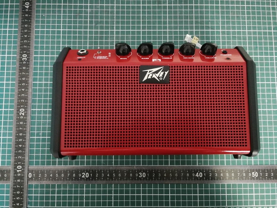
I4S-F1
Apr 24, 2026Active BT Wireless Speaker & Portable Instrument Amplifier
Equipment Class
DSS - Part 15 Spread Spectrum TransmitterI4S-SOLO
Apr 10, 2024Powered Speaker
Equipment Class
DSS - Part 15 Spread Spectrum Transmitter
I4S-AQ
Dec 18, 2022Powered Speaker
Equipment Class
DTS - Digital Transmission System
I4S-LN1063
Nov 19, 2020Column Array Powered Speaker System
Equipment Class
DSS - Part 15 Spread Spectrum Transmitter