I4S-WFS370WFS3.70
Peavey Electronics Corporation
Click to zoom
Application Details
- Equipment Class
- DTS - Digital Transmission System
- Date of Grant
- Nov 18, 2013
- Application Purpose
- Original Equipment
- Date of Application
- Nov 18, 2013
- Equipment Note
- WFS3.70
- Frequency Range
- 2412.00000000 - 2462.00000000
- Country
- United States
Documents & Files
Document Text
Text extracted from the exhibit documents filed with the FCC. Open a document above to read the original.
Users Manual
www.peavey.com WFS 3.70 Active Speakers With AirPlay ® /WIFI Technology Operating Manual Intended to alert the user to the presence of uninsulated “dangerous voltage” within the product’s enclosure that may be of sufficient magnitude to constitute a risk of electric shock to persons. Intended to alert the user of the presence of important operating and maintenance (servicing) instructions in the literature accompanying the product. CAUTION: Risk of electrical shock — DO NOT OPEN! CAUTION: To reduce the risk of electric shock, do not remove cover. No user serviceable parts inside. Refer servicing to qualified service personnel. WARNING: To prevent electrical shock or fire hazard, this apparatus should not be exposed to rain or moisture‚ and objects filled with liquids‚ such as vases‚ should not be placed on this apparatus. Before using this apparatus‚ read the operating guide for further warnings. Este símbolo tiene el propósito, de alertar al usuario de la presencia de “(voltaje) peligroso” sin aislamiento dentro de la caja del producto y que puede tener una magnitud suficiente como para constituir riesgo de descarga eléctrica. Este símbolo tiene el propósito de alertar al usario de la presencia de instruccones importantes sobre la operación y mantenimiento en la información que viene con el producto. PRECAUCION: Riesgo de descarga eléctrica ¡NO ABRIR! PRECAUCION: Para disminuír el riesgo de descarga eléctrica, no abra la cubierta. No hay piezas útiles dentro. Deje todo mantenimiento en manos del personal técnico cualificado. ADVERTENCIA: Para prevenir choque electrico o riesgo de incendios, este aparato no se debe exponer a la lluvia o a la humedad. Los objetos llenos de liquidos, como los floreros, no se deben colocar encima de este aparato. Antes de usar este aparato, lea la guia de funcionamiento para otras advertencias. Ce symbole est utilisé dans ce manuel pour indiquer à l’utilisateur la présence d’une tension dangereuse pouvant être d’amplitude suffisante pour constituer un risque de choc électrique. Ce symbole est utilisé dans ce manuel pour indiquer à l’utilisateur qu’il ou qu’elle trouvera d’importantes instructions concernant l’utilisation et l’entretien de l’appareil dans le paragraphe signalé. ATTENTION: Risques de choc électrique — NE PAS OUVRIR! ATTENTION: Afin de réduire le risque de choc électrique, ne pas enlever le couvercle. Il ne se trouve à l’intérieur aucune pièce pouvant être reparée par l’utilisateur. Confiez I’entretien et la réparation de l’appareil à un réparateur Peavey agréé. AVIS: Dans le but de reduire les risques d’incendie ou de decharge electrique, cet appareil ne doit pas etre expose a la pluie ou a l’humidite et aucun objet rempli de liquide, tel qu’un vase, ne doit etre pose sur celui-ci. Avant d’utiliser de cet appareil, lisez attentivement le guide fonctionnant pour avertissements supplémentaires. Dieses Symbol soll den Anwender vor unisolierten gefährlichen Spannungen innerhalb des Gehäuses warnen, die von Ausreichender Stärke sind, um einen elektrischen Schlag verursachen zu können. Dieses Symbol soll den Benutzer auf wichtige Instruktionen in der Bedienungsanleitung aufmerksam machen, die Handhabung und Wartung des Produkts betreffen. VORSICHT: Risiko — Elektrischer Schlag! Nicht öffnen! VORSICHT: Um das Risiko eines elektrischen Schlages zu vermeiden, nicht die Abdeckung enfernen. Es befinden sich keine Teile darin, die vom Anwender repariert werden könnten. Reparaturen nur von qualifiziertem Fachpersonal durchführen lassen. WARNUNG: Um elektrischen Schlag oder Brandgefahr zu verhindern, sollte dieser Apparat nicht Regen oder Feuchtigkeit ausgesetzt werden und Gegenstände mit Flüssigkeiten gefuellt, wie Vasen, nicht auf diesen Apparat gesetzt werden. Bevor dieser Apparat verwendet wird, lesen Sie bitte den Funktionsführer für weitere Warnungen. Intended to alert the user to the presence of uninsulated “dangerous voltage” within the product’s enclosure that may be of sufficient magnitude to constitute a risk of electric shock to persons. Intended to alert the user of the presence of important operating and maintenance (servicing) instructions in the literature accompanying the product. CAUTION: Risk of electrical shock — DO NOT OPEN! CAUTION: To reduce the risk of electric shock, do not remove cover. No user serviceable parts inside. Refer servicing to qualified service personnel. WARNING: To prevent electrical shock or fire hazard, this apparatus should not be exposed to rain or moisture‚ and objects filled with liquids‚ such as vases‚ should not be placed on this apparatus. Before using this apparatus‚ read the operating guide for further warnings. Este símbolo tiene el propósito, de alertar al usuario de la presencia de “(voltaje) peligroso” sin aislamiento dentro de la caja del producto y que puede tener una magnitud suficiente como para constituir riesgo de descarga eléctrica. Este símbolo tiene el propósito de alertar al usario de la presencia de instruccones importantes sobre la operación y mantenimiento en la información que viene con el producto. PRECAUCION: Riesgo de descarga eléctrica ¡NO ABRIR! PRECAUCION: Para disminuír el riesgo de descarga eléctrica, no abra la cubierta. No hay piezas útiles dentro. Deje todo mantenimiento en manos del personal técnico cualificado. ADVERTENCIA: Para prevenir choque electrico o riesgo de incendios, este aparato no se debe exponer a la lluvia o a la humedad. Los objetos llenos de liquidos, como los floreros, no se deben colocar encima de este aparato. Antes de usar este aparato, lea la guia de funcionamiento para otras advertencias. Ce symbole est utilisé dans ce manuel pour indiquer à l’utilisateur la présence d’une tension dangereuse pouvant être d’amplitude suffisante pour constituer un risque de choc électrique. Ce symbole est utilisé dans ce manuel pour indiquer à l’utilisateur qu’il ou qu’elle trouvera d’importantes instructions concernant l’utilisation et l’entretien de l’appareil dans le pa…
Text truncated - open the document above for the full version.
Attestation Statements
Specification 1. Electrical Properties : 1.1 1.2 1.3 1.4 1.5 1.6 2. Physical Properties : 2.1 2.2 2.3 2.4 Connector.................. ...SMA Standard Plug Operating Temp. ......... ... -20°C ~ +65°C Storage Temp. ............ ... -30°C ~ +75°C Polarization....................Vertical Radiation.................. ...Omni Cable........................ ...RG-178 Coaxial cable Impedance .................. 50Ω VSWR ..................... ... ≤2.0 Gain ........................ 2.0dBi RF Antenna Assembly Frequency Range............2.4-2.5GHz
External Photos
FCC ID: I4S-WFS370 IC: 3642A-WFS370 Page 1 of 3 External Picture FCC ID: I4S-WFS370 IC: 3642A-WFS370 Page 2 of 3 FCC ID: I4S-WFS370 IC: 3642A-WFS370 Page 3 of 3 RF Antenna AC/DC adapter
ID Label/Location Info
A This device complies with Part 15 of the FCC Rules / Industry Canada licence-exempt RSS standard(s). Operation is subject to the following two conditions: (1) this device may not cause harmful interference, and (2) this device must accept any interference received, including interference that may cause undesired operation. The Label would be showed on the EUT by silkscreen. Label Position
Internal Photos
FCC ID: I4S-WFS370 IC: 3642A-WFS370 Page 1 of 8 Internal Picture FCC ID: I4S-WFS370 IC: 3642A-WFS370 Page 2 of 8 Inside View for Right Speaker FCC ID: I4S-WFS370 IC: 3642A-WFS370 Page 3 of 8 FCC ID: I4S-WFS370 IC: 3642A-WFS370 Page 4 of 8 FCC ID: I4S-WFS370 IC: 3642A-WFS370 Page 5 of 8 FCC ID: I4S-WFS370 IC: 3642A-WFS370 Page 6 of 8 RF module FCC ID: I4S-WFS370 IC: 3642A-WFS370 Page 7 of 8 FCC ID: I4S-WFS370 IC: 3642A-WFS370 Page 8 of 8 Inside View for Left Speaker
RF Exposure Info
FCC ID: I4S-WFS370 IC: 3642A-WFS370 Page 1 of 2 Statement of compliance to Maximum Permissible Exposure (MPE) Applicant : Peavey Electronics Corporation 5022 Hartley Peavey Drive, Meridian, Mississippi, 39302, United States Manufacturer : Hansong (Nanjing) Technology Ltd. 8 Kangping Road, jiangning Econ. And Tech. Development Zone, Nanjing, 211106, China Equipment : WFS3.70 WiFi Speaker Type/Model : WFS3.70 According to §2.1091, §2.1093 and §1.1307(b), systems operating under the provisions of this section shall be operated in a manner that ensures that the public is not exposed to radio frequency energy level in excess of the Commission’s guidelines. The S = PG / (4πR²) Where S = power density in mW/cm² P = transmit power in mW G = numeric gain of transmit antenna R = distance (cm) R is chosen to be 20cm, the gain of antenna G = 2.00dBi = 1.585 As we can see from the test reports 130400373SHA-001: The maximum output power = -6.21dBm = 0.239mW MPE = PG / (4πR²) = 0.239 * 1.585 / (4 * 3.14 * 20 * 20) = 7.5 X 10 -5 mW/cm² which is below the MPE limit (≤1.0) defined in §1.1310. Date of issue: May 13, 2013 Prepared by: Reviewed by: Wakeyou Wang (Project Engineer) Daniel Zhao (Reviewer) FCC ID: I4S-WFS370 IC: 3642A-WFS370 Page 2 of 2 Appendix I Definition below must be outlined in the User Manual: To satisfy FCC RF exposure requirements, a separation distance of 20 cm or more should be maintained between the antenna of this device and persons during device operation. To ensure compliance, operations at closer than this distance is not recommended.
Test Report
FCC ID: I4S-WFS370 IC: 3642A-WFS370 Page 1 of 41 EMC TEST REPORT for Intentional Radiator No. 130400373SHA-001 Applicant : Peavey Electronics Corporation 5022 Hartley Peavey Drive, Meridian, Mississippi, 39302, United States Manufacturer : Hansong (Nanjing) Technology Ltd. 8 Kangping Road, jiangning Econ. And Tech. Development Zone, Nanjing, 211106, China Equipment : WFS3.70 WiFi Speaker Type/Model : WFS3.70 SUMMARY The equipment complies with the requirements according to the following standard(s): 47CFR Part 15 (2012): Radio Frequency Devices ANSI C63.4 (2003): American National Standard for Methods of Measurement of Radio-Noise Emissions from Low-Voltage Electrical and Electronic Equipment in the Range of 9 kHz to 40 GHz RSS-210 Issue 8 (December 2010): Low-power Licence-exempt Radiocommunication Devices (All Frequency Bands): Category I Equipment RSS-Gen Issue 3 (December 2010): General Requirements and Information for the Certification of Radiocommunication Equipment Date of issue: Aug 30, 2013 Prepared by: Reviewed by: Wakeyou Wang (Project Engineer) Daniel Zhao (Reviewer) FCC ID: I4S-WFS370 IC: 3642A-WFS370 Page 2 of 41 Description of Test Facility Name: Intertek Testing Services Limited Shanghai Address: Building No.86, 1198 Qinzhou Road(North), Shanghai 200233, P.R. China FCC Registration Number: 236597 IC Assigned Code: 2042B-1 Name of contact: Steve Li Tel: +86 21 64956565 ext. 214 Fax: +86 21 54262335 ext. 214 FCC ID: I4S-WFS370 IC: 3642A-WFS370 Page 3 of 41 Content SUMMARY .......................................................................................................................................................... 1 1. GENERAL INFORMATION ............................................................................................................................ 4 1.1 Applicant Information ..................................................................................................... 4 1.2 Identification of the EUT ................................................................................................ 4 1.3 Technical specification ................................................................................................... 5 1.4 Mode of operation during the test / Test peripherals used .............................................. 5 2. TEST SPECIFICATION .................................................................................................................................. 6 2.1 Instrument list ................................................................................................................. 6 2.2 Test Standard .................................................................................................................. 6 2.3 Test Summary ................................................................................................................. 7 3. MINIMUM 6DB BANDWIDTH ....................................................................................................................... 9 3.1 Limit ................................................................................................................................ 9 3.2 Test Configuration .......................................................................................................... 9 3.3 Test Procedure and test setup .......................................................................................... 9 3.4 Test Protocol ................................................................................................................. 10 4. MAXIMUM PEAK OUTPUT POWER ............................................................................................................. 14 4.1 Test limit ....................................................................................................................... 14 4.2 Test Configuration ........................................................................................................ 14 4.3 Test procedure and test setup ........................................................................................ 14 4.4 Test protocol ................................................................................................................. 15 5. POWER SPECTRUM DENSITY ..................................................................................................................... 19 5.1 Test limit ....................................................................................................................... 19 5.2 Test Configuration ........................................................................................................ 19 5.3 Test procedure and test setup ........................................................................................ 19 5.4 Test Protocol ................................................................................................................. 20 6. RADIATED EMISSION ................................................................................................................................. 24 6.1 Test limit ....................................................................................................................... 24 6.2 Test Configuration ........................................................................................................ 24 6.3 Test procedure and test setup ........................................................................................ 25 6.4 Test protocol ................................................................................................................. 26 7. EMISSION OUTSIDE THE FREQUENCY BAND ............................................................................................. 30 7.1 Limit .............................................................................................................................. 30 7.2 Test Configuration ........................................................................................................ 30 7…
Text truncated - open the document above for the full version.
Test Setup Photos
FCC ID: I4S-WFS370 IC: 3642A-WFS370 Page 1 of 3 Test Setup FCC ID: I4S-WFS370 IC: 3642A-WFS370 Page 2 of 3 1. Radiated Emission 30MHz-1000MHz FCC ID: I4S-WFS370 IC: 3642A-WFS370 Page 3 of 3 Higher than 1GHz
Contact Information
Applicant
Mark Wu(Product Compliance Manager)
Technical Contact
Intertek Testing Services Limited ShanghaiWakeyou Wang
[email protected]86 21 61278448
Building No.86, 1198 Qinzhou Road(North) · Shanghai · China
Test Firm
Intertek Testing Services Limited ShanghaiJonny Jing
Technical Specifications
| # | Rule Parts | Frequency Range | Power Output |
|---|---|---|---|
| 1 | 15C | 2.41 GHz - 2.46 GHz | 239.00 mW |
Other Applications from Peavey Electronics Corporation

I4S-MESSENGER
Sep 03, 2026Active BT Wireless Speaker & Portable Instrument Amplifier
Equipment Class
DSS - Part 15 Spread Spectrum Transmitter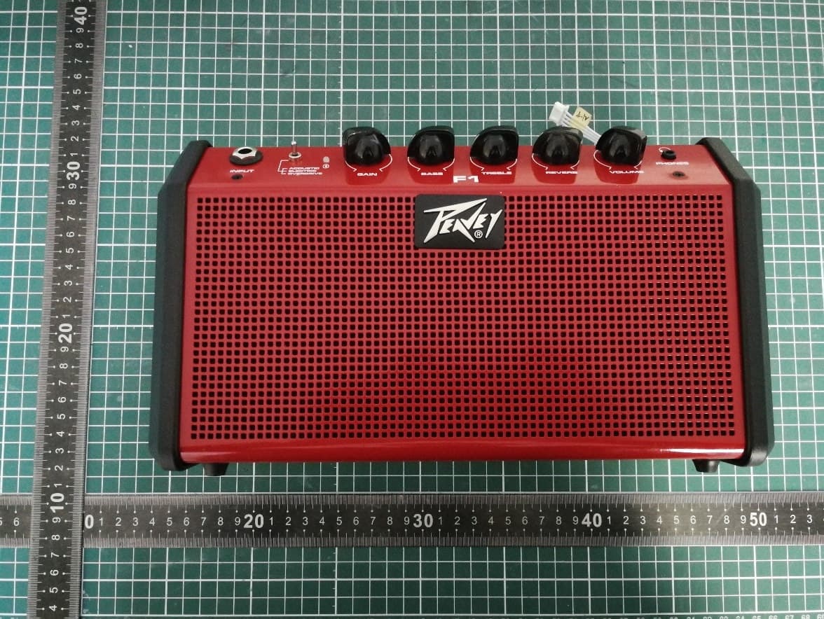
I4S-F1
Apr 24, 2026Active BT Wireless Speaker & Portable Instrument Amplifier
Equipment Class
DSS - Part 15 Spread Spectrum TransmitterI4S-SOLO
Apr 10, 2024Powered Speaker
Equipment Class
DSS - Part 15 Spread Spectrum Transmitter
I4S-AQ
Dec 18, 2022Powered Speaker
Equipment Class
DTS - Digital Transmission System
I4S-LN1063
Nov 19, 2020Column Array Powered Speaker System
Equipment Class
DSS - Part 15 Spread Spectrum Transmitter