IHDT6ZB1PCS portable phone
Motorola Mobility LLC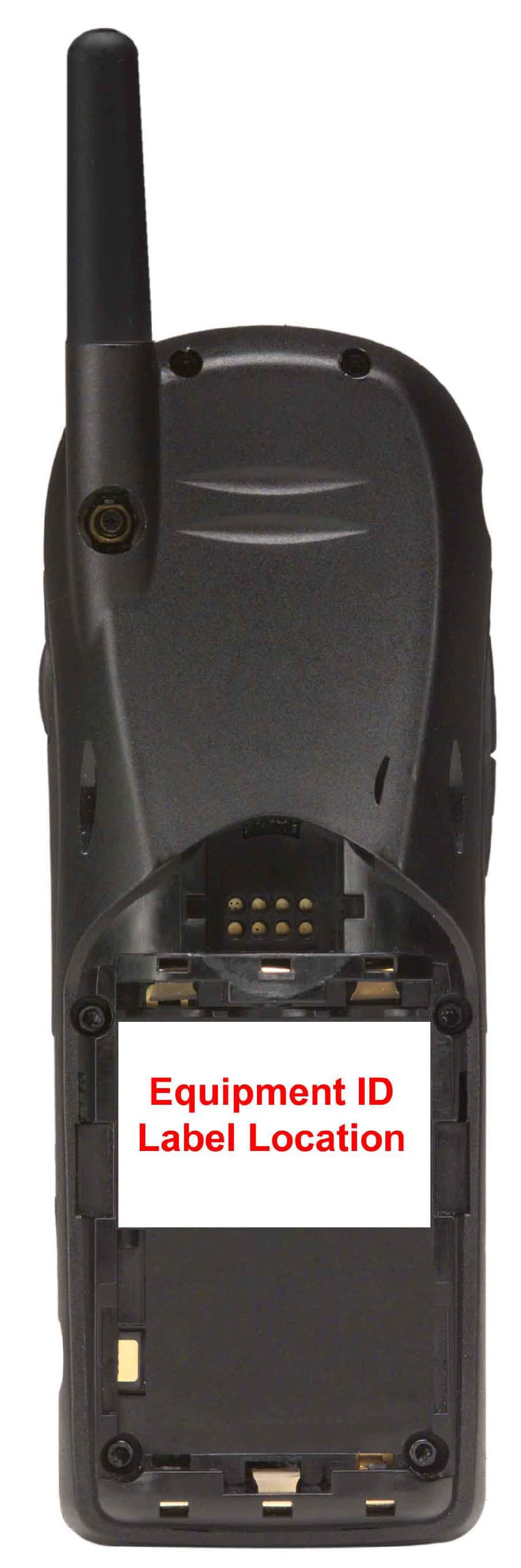
Click to zoom
Application Details
- Equipment Class
- PCE - PCS Licensed Transmitter held to ear
- Date of Grant
- Mar 23, 2000
- Application Purpose
- Original Equipment
- Date of Application
- Dec 06, 1999
- Equipment Note
- PCS portable phone
- Frequency Range
- 1850.20000000 - 1909.80000000
- Company
- Motorola Mobility LLC
- Country
- United States
Documents & Files
Document Text
Text extracted from the exhibit documents filed with the FCC. Open a document above to read the original.
Users Manual
APPLICANT: MOTOROLA, INC.FCC ID: IHDT6ZB1 EXHIBIT 8 INSTRUCTION MANUAL A preliminary draft copy of the Users Manual follows: Note The final version of the Users Manual will contain the following additional statement: To ensure compliance with FCC exposure guidelines, only use the Motorola supplied carrying case, holster or other body-worn accessory for this product. English Options Menu Quick Access ‡ Quick Reference m3gdr_en.bk : qkref.fm5 Page 1 Tuesday, October 26, 1999 12:46 PM English Special Keys S Press to turn phone on and off. O Press to accept call, setting, option,... C Press to reject call, setting, option,... E Press to enter the Quick Access features. $ Press to access the options or phone book menus. <> Press both simultaneously to lock the keypad; also use to scroll left and right. æø Press to scroll up and down. f Press to call Voicemail. Making a Call Enter C O . Receiving a Call Press O . Ending a Call Press O or C . Making an Emergency Call Enter 112O . The call will be directed to a central emergency operator. Quick Access Features Press E followed by the appropriate key, or press E , scroll to the feature and press O to select. Adjust Ringer Volume Press E followed by the volume button to either increase or decrease the ringer volume. Redialling the Last Number Called 1 Press O to display the last number dialled. 2 Press O to call the number. One-Touch Dialling Press and hold the appropriate digit key 1 to 9 . Storing Numbers in the Phone Book Press E2 to store a number on the SIM card. Recalling a Number from the Phone Book Use the volume button to scroll to the stored number, or press the appropriate digit key to skip to a particular letter. To make the call, press O . Dialling Phone Book Numbers Enter G >O . Stopping a Call Alert Press the volume button when the phone is ringing. This will stop the alert but not answer the call. Quick Reference m3gdr_en.bk : qkref.fm5 Page 2 Tuesday, October 26, 1999 12:46 PM Introduction 1 English Introduction Welcome Congratulations on your purchase of a mobile phone from Motorola , the world leader in cellular technology. The phones are packed with features that put you in control and give you unrivalled power, whilst remaining discrete. Control • Customisable Quick Access Menu E - Place nine of your most frequently used features in your own personal menu so that they can be accessed with just two key presses. Icons make each feature easy to identify. Power • Superb battery performance G - Each phone is capable of several hours conversation or several days standby, but is still small and light. • Dual Band Æ - versions of the phone include the powerful dual band feature which means that they can use 900 and 1800MHz bands for greater call success and allow wider roaming opportunities. ! Before you use your phone, please see the ‘Your Battery’ section for important information on charging a new battery. Enjoyment and Entertainment • FM Radio - Pre-set your favourite station or seek for your listening enjoyment. • WAP - Easy keypad Internet access and fast delivery of information. Personality™ This cellular telephone incorporates Personality ™. Unique to Motorola , Personality ™ removes the complexity of cellular communications by guiding you through the features and presenting you with simple choices every step of the way. Personality ™ also allows you to personalise the way you use your phone - for example, different ringer tones, a phone book and network selection preferences - all presented with clarity and simplicity. In this manual, each of the Personality ™ features is identified with an j symbol to indicate that it is customisable to meet your requirements. m3gdr_en.bk : intro.fm5 Page 1 Tuesday, October 26, 1999 12:46 PM Introduction 2 English Understanding this Manual Many of your phone options are accessed by a simple menu system. A full description of the menus and how to move around them is covered in the next section Menu Navigation . When the manual describes the use of each menu item, it will be assumed that you are familiar with the menu system. Key Presses Key presses are represented in this manual using symbols so that you may locate and use the required sequence quickly. A sequence of key presses may be shown as follows:$OCThis means that you should press the $ key followed by the O key and then the C key, in sequence, not simultaneously. Entering Information When you are requested to enter information, such as the number of the phone you wish to call, this is represented in bold type. For example:C - enter the required telephone number. A - enter your Personal Identification Number. B - enter your unlock code. G - enter the Phone Book location number. Prompts and Messages Your phone responds to key presses by displaying either easy to understand prompts that guide you to the next action, or simple messages confirming that your action is complete. Prompts and messages are represented in this manual in LCD style, for example:Enter PIN or Completed . Other Symbols You will find the following symbols used throughout this manual:A A Note contains additional information which is relevant to the feature/item. ! A Caution contains important additional information which is relevant to the efficient and/or safe usage of your phone. j This symbol indicates that the feature is a Personality ™ feature that can be customised to meet your requirements. i This symbol indicates a short key sequence for the feature. m3gdr_en.bk : intro.fm5 Page 2 Tuesday, October 26, 1999 12:46 PM Introduction 3 English Menu Navigation A large number of your phone's options are accessed by using menus which use a common approach for selection, change and cancellation.Please read this section carefully before attempting to access a menu option. When you understand the common approach to menu navigation and how the menus are shown on the page, you will be able to access and change options with ease. Entering the Menus Two different keys are used…
Text truncated - open the document above for the full version.
Attestation Statements
APPLICANT: MOTOROLAFCC ID: IHDT6ZB1 EXHIBIT 2A December 6 1999 SPECIFICATION COMPLIANCE STATEMENT Engineer-in-Charge Equipment Authorization Branch Federal Communications Commission The transceiver type IHDT6ZB1 has been tested in accordance with the requirements contained in the appropriate Commission regulations. To the best of my knowledge, these tests were performed using measurement procedures consistent with industry or Commission standards and demonstrate that this equipment complies with the appropriate standards. Each unit manufactured imported or marketed, will conform to the sample tested within the variations that can be expected due to quantity production and testing on a statistical basis. I further certify that the necessary measurements were made at Motorola, located at 600 North U.S. Highway 45 , Libertyville, Illinois with the exception of Radiated Spurious Emissions testing which took place at Elite Electronics Engineering Company, located at 1516 Center Circle, Downers Grove, Illinois. NAME:MARK LACHIW TITLE:ENGINEERING MANAGER PCS Development APPLICANT: MOTOROLAFCC ID: IHDT6ZB1 EXHIBIT 2B STATEMENT OF CERTIFICATION The technical data supplied with this application, was taken under my supervision is hereby duly certified. The following is a statement of my qualifications : NAME:NIGHAT RAHIM TITLE:Senior Engineer PCS Development Signed: Date: I hereby certify that the above application was prepared under my direction and that to the best of my knowledge and belief, the facts set forth in this application and accompanying technical data are true and correct. NAME:Henry Chin TITLE:Section Manager PCS Development Signed: Date:
Cover Letter(s)
APPLICANT: MOTOROLAFCC ID: IHDT6ZB1 Exhibit 13 December 7, 1999 CONFIDENTIALITY REQUEST CONTAINED WITHIN Federal Communications Commission Authorization and Evaluation Division 7435 Oakland Mills Road Columbia, Maryland 21046 Re: Application for Cellular/PCS Transceiver Certification Gentlemen: Application: Motorola, Inc., Personal Communications Sector, 600 N. U.S. Highway 45, Libertyville, Illinois 60048-1286 herein submits: Application for Equipment Authorization (FCC Form 731-October 1992 with integrated Fee Processing Form, Fee Codes EFT and EBC), application fee in the amount of $610, and Exhibits; for Certification of a PCS Transceiver, FCC ID: IHDT6ZB1. Motorola is also the manufacturer of this equipment. Confidentiality: Pursuant to Section 0.459 of the Commission's rules (CFR 47), Motorola requests confidentiality for portions of the material contained in this application and that the identified material be withheld from public inspection following the grant of this authorization. This material contains Motorola's trade secrets and confidential information that Motorola does not customarily release to the public and which is otherwise not generally available to the public. Confidentiality is requested for the following exhibits: • Exhibit 4 Block Diagrams • Exhibit 5 Schematics • Exhibit 12 Operational Description Description: This equipment is a GSM portable transceiver, which operates in the 1900 MHz PCS band Contact Information: Please contact me by telephone at (847) 523-6167, by facsimile at (847) 523-2350, or by e-mail ([email protected]), if there are questions or additional information needed concerning this filing. Regards, Andrew J. Bachler FCC Liaison Cellular Subscriber Sector 600 N. U.S. Highway 45 Libertyville, IL 60048-5343
External Photos
APPLICANT: MOTOROLA, INC. FCC ID: IHDT6ZB1 EXHIBIT 3 Front View Back View (Battery Removed to Show Equipment ID)
ID Label/Location Info
APPLICANT: MOTOROLA, INC.FCC ID : IHDT6ZB1 EXHIBIT 1 FCC IDENTIFICATION (NAMEPLATE) INFORMATION The FCC label shown is representative of the label that will appear on the radio when in production. It will be placed on the radio telephone as shown in Exhibit 3. Other information may also be included on this label. FCC ID: IHDT6ZB1
Internal Photos
APPLICANT: MOTOROLA, INC. FCC ID: IHDT6ZB1 EXHIBIT 9 Front View (Shields Removed) Rear View (Shields Removed)
Parts List/Tune Up Info
APPLICANT: MOTOROLA, INC.FCC ID: IHDT6ZB1 EXHIBIT 10 TRANSCEIVER ADJUSTMENTS/TUNE-UP PROCEDURE There are no user accessible adjustments or tuning in this portable cellular transceiver. All necessary adjustments and tuning are performed during manufacture of the product. Any adjustments or tuning after service or repair are done as part of that process as special equipment is required to perform such adjustments.
RF Exposure Info
P P a a g g e e 1 1 December 3, 1999 SAR Test Report for Motorola portable cellular phone (FCC ID IHDT6ZB1). Prepared by: Paul Moller, Principal Staff Engineer Motorola Personal Communications Sector Product Safety Laboratory Libertyville, Illinois Contents 1) Introduction 2) Applicable Regulations 3) Description of Test Sample 4) Description of Motorola SAR Test Facility 5) Test Sample Conditions 6) Method of Measurement 7) Measurement Uncertainty 8) SAR Test Results 9) Body Worn Configuration 10) Battery Options 11) Summary Appendix A: Included data Appendix B: Included beltclip data Appendix C: Measurement Probe S/N 1393 Calibration Certificate Appendix D: Printout from the Dasy measurement system validation test P P a a g g e e 2 2 1. Introduction The Motorola Personal Communications Sector Product Safety Laboratory has performed measurements of the maximum potential exposure to the user of portable cellular phone FCC ID IHDT6ZB1. The Specific Absorption Rate (SAR) of this product was measured. This report details the test setup and equipment as well as the results of those tests. 2. Applicable Regulations Federal Communications Commission rule §2.1093(d)(2), the ANSI/IEEE C95.1 1992 and the NCRP Report Number 86 specify the maximum exposure limit of 1.6 W/kg as averaged over any 1 gram of tissue for portable devices being used within 20cm of the user in the uncontrolled environment. 3. Description of Test Sample A prototype unit with serial number 991117-A was measured. This unit is identical in physical construction, maximum radiated power levels and antenna structure to units that will be in production. It transmits in the frequency range of 1850 to 1910 MHz using GSM mode. The unit was tested at its maximum transmitter power. The unit is equipped with a fixed antenna that serves as both a receive and transmit antenna. The antenna has a single operating position as shown in figure 1 and figure 2. Figure 1. Front of Phone Figure 2. Side of Phone P P a a g g e e 3 3 Figure 3 shows the test unit as it is placed onto the Motorola phantom. For the purposes of the actual SAR tests the Motorola phantom head is tilted on its side by 90 degrees so that a vertically oriented measurement probe can easily scan an area where the phone is in close contact with the phantom and the SAR will be the highest. Figure 3. Phone against side of Phantom Head. 4. SAR Test Facility The Motorola test facility utilized for the SAR testing of this product is the Personal Communications Sector Product Safety Laboratory, in Libertyville Illinois. The laboratory utilizes a Dosimetric Assessment System (Dasy™) SAR measurement system manufactured by Schmid & Partner Engineering AG (SPEAG™), of Zurich Switzerland. This system utilizes a computer controlled six axis robot to move a measurement probe to measure the SAR. A photo of the Dasy system with the Motorola phantom is shown in figure 4. Probe serial number 1391 was used for the measurements. It was calibrated at SPEAG™, and has a calibration date October 6, 1999. A copy of the calibration certificate is included as appendix D. Dipole Validation Kit type D1800V2, serial number 246 was used to validate the system accuracy at 1900MHz. The validation SAR value is 37.7 mW/g normalized to 1 Watt, and the Dasy system used for the test phone measured 39.3 mW/g normalized to 1 Watt. This is within the required accuracy, and thus P P a a g g e e 4 4 the measured SAR values are considered correct. See appendix E for printout of the validation test from the Dasy measurement system. The measurement methodology is described in IEEE Transactions on Vehicular Technology, vol. 44, no. 3, August 1995, titled Electromagnetic Energy Exposure of Simulated users of Portable Cellular Telephones. The Dasy system is operated per the instructions in the Dasy Users Manual. The entire manual is available directly from SPEAG. Figure 4. Dasy System 5. Test Sample Conditions For the purposes of these tests the subject phone was positioned on the measurement phantom per the instructions in the Motorola users manual for the subject phone. The position used for the tests is the 3-point contact position. In this position the test sample contacts the phantom’s ear and cheek and is positioned with a repeatability of better than ±6%. Since the antenna is not located on the center of the phone, the SAR was measured with the phone on both the left and right side talk positions (See figure 3). Due to the construction of the phone, the base of the antenna is 26 mm away from the phantom for the left side head, which is the closest. P P a a g g e e 5 5 The test sample is capable of operation in a test mode that allows control of the transmitter without the need to place actual phone calls. This guarantees that the unit does not change its transmitter power, and that the resultant SAR values will not be affected by external connections. For the purposes of this test the unit is commanded to test mode and manually set to the proper channel, transmitter power level and transmit mode of operation. The phone is then placed in the SAR measurement system with a fully charged battery. At the end of each test the Dasy system measures the drift of the SAR at a fixed point in the phantom so as to ensure that the test sample has not changed in transmitter power. For the purposes of these tests, the transmitter was operated at the highest transmitter output and with the phone and module on both left and right side talk positions. 6. Method of Measurement The system is instructed to scan as much of the face of the phone as is in close proximity to the phantom. Using the information gained about the general region of highest SAR, the system then automatically scans a smaller area centered around the location of peak spatial SAR. During this scan the system automatically measures the fall off of electric field strength as the measurement probe is moved away from the inner surface of the phantom in the directio…
Text truncated - open the document above for the full version.
RF Exposure Info
Safety 11 English Safety Information IMPORTANT Read this information before using your wireless handheld phone. Exposure To Radio Frequency Signals Your wireless handheld portable telephone is a low power radio transmitter and receiver. When it is ON, it receives and also sends out radio frequency (RF) signals.In August 1996, The Federal Communications Commission (FCC) adopted RF exposure guidelines with safety levels for handheld wireless phones. Those guidelines are consistent with safety standards previously set by both U.S. and international standards bodies:• American National Standards Institute (ANSI) IEEE. C95. 1-1992 • National Council on Radiation Protection and Measurement (NCRP). Report 86 • International Commission on Non-Ionizing Radiation Protection (ICNIRP) 1996 • Ministry of Health (Canada), Safety Code 6 Those standards were based on comprehensive and periodic evaluations of the relevant scientific literature. For example, over 120 scientists, engineers, and physicians from universities, government health agencies, and industry reviewed the available body of research to develop the ANSI Standard (C95.1). The design of your phone complies with the FCC guidelines (and those standards). For additional information concerning exposure to radio frequency signals, see the statement by the FDA at the end of this user guide.To maintain compliance with FCC RF exposure guidelines, if you wear a handset on your body, use the Motorola-supplied or approved carrying case, holster, or other body-worn accessory. If you do not use a body-worn accessory, ensure the antenna is at least one inch (2.5 centimeters) from your body when transmitting. Use of non-Motorola accessories may violate FCC RF exposure guidelines. Antenna Care Use only the supplied or an approved replacement antenna. Unauthorized antennas, modifications, or attachments could damage the phone and may violate FCC regulations. Phone OperationNormal Operation Hold the phone as you would any other telephone, with the antenna pointed up and over your shoulder. Tips on Efficient Operation Observe the following guidelines to operate your phone most efficiently.• Extend your antenna fully, if applicable. m3gst_en.bk : safety.fm5 Page 11 Friday, March 3, 2000 3:19 PM
RF Exposure Info
March 22, 2000 Supplement to SAR Test Report for Motorola portable cellular phone (FCC ID IHDT6ZB1). Prepared by: Paul Moller, Principal Staff Engineer Motorola Personal Communications Sector Product Safety Laboratory Libertyville, IL Contents 1) Summary of FCC request for additional information 2) Additional Pictures of Body-Worn Configuration 3) Retest of Body-Worn Configuration Appendix A: Included data P P a a g g e e 2 2 1. Summary of FCC request for additional information There was a request for additional information regarding relationship between the use of the product and the SAR test data submitted with the Report for Motorola’s portable cellular phone (FCC ID IHDT56ZF1) dated March 7, 2000. The requested information may be summarized as follows: 1. The setup photo included in the SAR report for body-worn configuration does not clearly identify the belt-clip and antenna position. Please provide a separate photo to identify the body-worn SAR test setup. The antenna on this device tilts back towards the body (for body-worn), please clarify if the peak SAR location indicated in the SAR plot is associated with the body of the handset or the antenna. 2. The dielectric constant of tissue parameters used for body-worn SAR tests are too low, where field distributions and conditions could be substantially different than normally expected - about 54 for muscle at 1900 MHZ and 34.9 was used (34 is for muscle above 15 GHz). The difference in field gradients and energy attenuation could result in substantially different 1-g averaged SAR. The difference in parameter could also result in greater uncertainty in E-field probe calibration and SAR results. When there is substantial difference in dielectric parameters, it could becomes difficult to extrapolate 1-g SAR to account for parameter differences. Please comment accordingly or provide test data using appropriate muscle equivalent parameters. 2. Additional Pictures of Body-Worn Configuration An additional photo showing the phone in the body-worn configuration is shown in figure 1. Figure 1. Phone in Body-Worn Configuration P P a a g g e e 3 3 The peak SAR location when used in the body-worn configuration is located near the antenna of the phone. The contour plot overlaid on the back of the phone with the belt-clip on is shown in figure 2. Figure 2. Contour Plot overlaid on Body-Worn Configuration 3. Retest of Body-Worn Configuration The phantom was filled with a liquid having relative dielectric constant equal to 49.4 and conductivity equal to 1.64 S/m. This mixture is a good dielectric equivalent of muscle in the human body. The composition of the liquid mixture is as follows: 66.1% water; 33.40% Diethylene Gylcol Butyl Ether; 0.5% salt. The highest SAR value was found at the channel 660. The data output of the test condition with the highest SAR values from the Dasy measurement system is included as appendix A. Appendix A The following pages are printouts from the Dasy measurement system of the data as indicated. s/n 991117-A Ch660/ Pwr 00/ BeltClip Amy Twin Phantom Phantom; Section 1 Section; Position: (0°,0°); Frequency: 1880 MHz Probe: ET3DV6 - SN1506 - Muscle; ConvF(5.67,5.67,5.67); Crest factor: 8.0; Glycol 1900mhz: σ = 1.64 mho/m ε r = 49.4 ρ = 1.00 g/cm 3 Cube 5x5x7: SAR (1g): 0.247 mW/g, SAR (10g): 0.150 mW/g, (Worst-case extrapolation) Coarse: Dx = 15.0, Dy = 15.0, Dz = 10.0 Penetration depth: 9.7 (8.6, 11.5) [mm] Powerdrift: -0.59 dB SAR Tot [mW/g] 2.65E-2 5.30E-2 7.95E-2 1.06E-1 1.33E-1 1.59E-1 1.86E-1 2.12E-1 2.39E-1 2.65E-1 03/22/00 Motorola, Inc.
Test Report
APPLICANT MOTOROLA INC. FCC ID: IHDT6ZB1 Exhibit 6 TEST REPORT SUBMITTED MEASURED DATA INDEX RF Power Output ...................................................... 6A EIRP ......................................................................... 6B Final Amplifier Voltages and Currents ...................... 6C Radiated Spurious Emission..................................... 6D Occupied Bandwidth................................................. 6E Conducted Spurious Emissions ................................ 6F Frequency Stability ...................................................6G APPLICANT MOTOROLA INC. FCC ID: IHDT6ZB1 Exhibit 6A RF Output Power Exhibit Summary This exhibit contains both average and peak output powers for the mobile station. In all cases, the peak output power is within the required mask (this mask is specified in the JTC standards, TIA PN3389 Vol. 1 Chap.7 and is not an FCC requirement). Contents Method of Measurement Measurement limit Average output powers EIRP Method of measurement 1. Setup the mobile station for maximum output power with pseudo random data modulation. 2. Use HP 8991A Peak Power Analyzer to obtain peak and average output power levels. 3. Repeat measurements for carrier frequencies for channel 512, 662 and 810 Measurement Limits Power Step Nominal Peak output power(dBm) Tolerance (dB) 0 30 +/-2 Conducted Power Output Frequency (MHz) Power Step Peak Output Power (dBm) Average Output Power (dBm) 1850.2030.321.3 1880.2030.521.5 1909.8030.321.3 APPLICANT MOTOROLA INC. FCC ID: IHDT6ZB1 Exhibit 6B EIRP TEST Description This is the test for the maximum radiated power from the phone. Rule Part 24.232(b) specifies that “Mobile /portable stations are limited to 2 watts e.i.r.p. peak power ..” and 24.232(c) specifies that “Peak transmit power must be measured over any interval of continuous transmission using instrumentation calibrated in terms of an rms-equivalent voltage.” Method of measurement: 1. In an anechoic antenna test chamber, a half-wave dipole antenna for the frequency band is placed et the reference center of the chamber. An RF signal source for the frequency band of interest is connected to the dipole with a cable that has been constructed to not interfere with the radiation pattern of the antenna. A known (measured) power (Pin) is applied to the dipole, and the power received (Pr) at the chamber’s probe antenna is recorded. 2. A “reference path loss” is established as Pin + 2.1 – Pr. 3. The EUT is substituted for the dipole at the reference center of the chamber. The EUT is put into CW test mode and a scan is performed to obtain the radiation pattern. 4. From the radiation pattern, the coordinates where the maximum antenna gain occurs is identified. 5. The EUT is then put into pulse mode at its maximum power level (power step 0). 6. “Gated mode “ power measurements are performed with the receiving antenna placed at the coordinates determined in step 3 to determine the output power as defined in FCC Rule 24.232 (b) and (c). The “reference path loss” from Step 1 is added to this result. 7. This value is EIRP since the measurement is calibrated using a half-wave dipole antenna of known gain (2.1dB) and known input power (Pin). 8. ERP can be calculated from EIRP by subtracting the gain of the dipole , ERP = EIRP – 2.1dBi. EIRP Limits EIRP (dBm) Burst Average<33 EIRP Measurements EIRP (dBm) ERP (dBm) Modulation average1916.9 Burst Average30.128 APPLICANT MOTOROLA INC. FCC ID: IHDT6ZB1 Exhibit 6C Final Amplifier Voltages and Currents Exhibit contains the voltages and currents applied to the TX Driver and TX Final Power Amplifier for the entire mobile station operating power range. Power Step Power Output Spec.(dBm) Power Output Meas.(dBm) Vcc Driver (VDC) Ic Driver (mA) Vcc Final (VDC) Ic Final (A) 030+/-230.494.7224.70.312 128+/-328.374.7914.70.264 226+/-327.84.7174.70.225 324+/-225.724.7154.70.212 422+/-323.434.7134.70.188 520+/-322.84.7124.70.178 618+/-318.894.7104.70.168 716+/-317.564.794.70.16 814+/-3144.784.70.153 912+/-412.984.774.70.147 1010+/-410.054.74.54.70.141 118+/-49.54.74.44.70.13 126+/-46.374.74.34.70.118 134+/-44.864.74.34.70.102 142+/-42.924.74.34.70.05 150+/-41.244.74.34.70.03 APPLICANT MOTOROLA INC. FCC ID: IHDT6ZB1 Exhibit 6D RADIATED SPURIOUS EMISSION Exhibit Summary The data were collected by Elite Electronics Engineering Company at their open field test site located at 1516 Centre Circle , Downers Grove , Illinois . The site is constructed in accordance with ANSI C63 requirements by the FCC to be in compliance with section 2.948 for a 3 meter site . The spectrum was scanned from 30MHz to the 10 th harmonic of the highest frequency generated within the equipment , which is the transmitted carrier that can be as high as 1910 MHz . This was rounded up to 20 GHz . The resolution bandwidth is set as outlined in part 24.238 . Attached is a copy of test procedure and results as submitted to Motorola by Elite Electronics Engineering ,along with an equipment list . Also attached are plots of the relevant radiated emission spurs that are within 20dB of the FCC limit of 43+10Log(P) or –13dBm . APPLICANT MOTOROLA INC. FCC ID: IHDT6ZB1 Exhibit 6D APPLICANT MOTOROLA INC. FCC ID: IHDT6ZB1 Exhibit 6D APPLICANT MOTOROLA INC. FCC ID: IHDT6ZB1 Exhibit 6D APPLICANT MOTOROLA INC. FCC ID: IHDT6ZB1 Exhibit 6D APPLICANT MOTOROLA INC. FCC ID: IHDT6ZB1 Exhibit 6D APPLICANT MOTOROLA INC. FCC ID: IHDT6ZB1 Exhibit 6D APPLICANT MOTOROLA INC. FCC ID: IHDT6ZB1 Exhibit 6D APPLICANT MOTOROLA INC. FCC ID: IHDT6ZB1 Exhibit 6D APPLICANT MOTOROLA INC. FCC ID: IHDT6ZB1 Exhibit 6D APPLICANT MOTOROLA INC. FCC ID: IHDT6ZB1 Exhibit 6D APPLICANT MOTOROLA INC. FCC ID: IHDT6ZB1 Exhibit 6D APPLICANT MOTOROLA INC. FCC ID: IHDT6ZB1 Exhibit 6D APPLICANT MOTOROLA INC. FCC ID: IHDT6ZB1 Exhibit 6D APPLICANT MOTOROLA INC. FCC ID: IHDT6ZB1 Exhibit 6D APPLICANT MOTOROLA INC. FCC ID: IHDT6ZB1 Exhibit 6D APPLICANT MOTOROLA INC. FCC ID: IHDT6ZB1 Exhibit 6D APPLICANT MOTOROLA INC. FCC …
Text truncated - open the document above for the full version.
Contact Information
Applicant
Jeff Narducci(Director Product Compliance)
Technical Specifications
| # | Rule Parts | Frequency Range | Power Output | Emission | Tolerance |
|---|---|---|---|---|---|
| 1 | 24E | 1.85 GHz - 1.91 GHz | 1.1 W | 250KGXW | 0.1000000000 ppm |
Other Applications from Motorola Mobility LLC
IHDT6AC8
Sep 15, 2026Qi2 wireless charger
Equipment Class
DCD - Part 15 Low Power Transmitter Below 1705 kHzIHDT6AC6
Sep 14, 2026Wireless Earphones
Equipment Class
JAB - Part 15 Class B Digital DeviceIHDT6AC7
Sep 11, 2026Smart Watch
Equipment Class
JAB - Part 15 Class B Digital DeviceIHDT56AX5
Aug 28, 2026Mobile Cellular Phone
Equipment Class
JBP - Part 15 Class B Computing Device PeripheralIHDT56AW9
May 12, 2026Smart Watch
Equipment Class
NII - Unlicensed National Information Infrastructure TX