IIO-CWP854Wireless-G PCI Adapter
CNet Technology Inc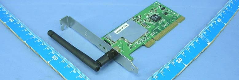
Click to zoom
Application Details
- Equipment Class
- DTS - Digital Transmission System
- Date of Grant
- Nov 24, 2004
- Application Purpose
- Original Equipment
- Date of Application
- Nov 24, 2004
- Equipment Note
- Wireless-G PCI Adapter
- Frequency Range
- 2412.00000000 - 2462.00000000
- Company
- CNet Technology Inc
- Country
- Taiwan
Documents & Files
Document Text
Text extracted from the exhibit documents filed with the FCC. Open a document above to read the original.
Users Manual
Use this User’s Guide to Install Wireless-G PCI Adapter Table of Contents 1. Introduction 1.1The Wireless-G PCI Adapter 1.2 Key Feature 2. Planning Your Wireless Network 2.1 Network Topology 2.2 Ad-Hoc versus Infrastructure Mode 3. Getting to Know the Wireless-G PCI Adapter 4. Installing Driver, Configuration Utility and Hardware for Windows 98SE/ME/2000/XP 4.1 Driver Installation for Windows 98SE/ME/2000/XP 4.2 Insert the Adapter 5. Using the Configuration Utility for Windows 98SE/ME/2000/XP 5.1 Overview 5.2 Access the Configuration Utility 5.3 Profile 5.4 Create a New Profile 5.5 Link Status 5.6 Site Survey 5.7 Statistics 5.8 Advance 5.9 About 6. Troubleshooting 1. Introduction 1.1 The Wireless-G PCI Adapter The Wireless-G PCI Adapter installs in most desktops and lets you put your computer almost anywhere in the building, without the cost and hassle of running network cables. Now you don't have to drill holes in your walls and climb through the attic or cellar to get connected to the network. Once you're connected, you can keep in touch with your e-mail, access the Internet, use instant messaging to chat with friends, and share files and other resources such as printers and network storage with other computers on the network. The Wireless-G PCI Adapter connects you with Wireless-G networks at an incredible 54Mbps! And for added versatility, it can also interoperate with all the 11Mbps Wireless-B (802.11b) products found in homes, businesses, and public wireless hotspots around the country. And in either mode, your wireless communications are protected by up to 128-bit encryption, so your data stays secure. So don't hassle with running cables through your house - get your desktop connected the easy way with the Wireless-G PCI Adapter. 1.2 Key Feature Investment Protection: 5 Times Faster and Interoperate with Existing Wireless-B Equipment Seamlessly 64/128-bit WEP and Advanced 256-bit WPA (Wi-Fi Protected Access) Encryption Provides Maximum Wireless Security Ease of Use: Simple Installation with the Help of the Simple Setup Wizard Compatible with Windows 98SE/ME/2000/XPhe Wireless-G PCI Adapter Features 2. Planning Your Wireless Network 2.1 Network Topology A wireless local area network (WLAN) is exactly like a regular local area network (LAN), except that each computer in the WLAN uses a wireless device to connect to the network. Computers in a WLAN share the same frequency channel and SSID, which is an identification name for wireless devices. 2.2 AD-Hoc versus Infrastructure Mode An Ad-Hoc wireless LAN is a group of computers, each equipped with one WLAN adapter, connected as an independent wireless LAN. Computers in a specific Ad-Hoc wireless LAN must be configured to share the same radio channel. The adapter provides access to a wired LAN for wireless workstations. An integrated wireless and wired LAN is called an infrastructure configuration. A group of adapter PC users and an Access Point and compose a Basic Service Set (BSS). Each adapter PC in a BSS can talk to any computer in the wired LAN infrastructure via the Access Point. Network Topology Ad-Hoc versus Infrastructure Mode 3. Getting to Know the Wireless-G PCI Adapter Wireless-G PCI Adapter will be installed into your PC like any other PCI adapter and on the mounting bracket, you will find two distinguishing items: ACT LED Green. The ACT LED will light up when the Adapter is powered on. Antenna Port Attach the PCI Adapter’s antenna here and position it for maximum performance, which is usually perpendicular to the horizon. 4. Installing Driver, Configuration Utility and Hardware for Windows 98SE/ME/2000/XP 4.1 Driver Installation for Windows 98SE/ME/2000/XP 4.1.1 Running the Auto Driver/Utility Installation Before installing your Wireless-G PCI Adapter, insert the Auto-Install CD into your CD-ROM driver. Unless you have deactivated the auto-run feature of Windows, the screen shown in Fig 4-1 should appear automatically. If this screen doesn’t appear automatically, you can access the installation by clicking the Start button and choosing Run. In the drop-down box provided type D:\Setup.exe (where D: is the letter of your CD-ROM driver). Alternately, double-click My Computer and double-click the Setup.exe icon in the folder that appears. Fig 4-1 Auto-run Feature of Windows 4.1.2 Click Install Wireless-G PCI Adapter Driver and Utility to install driver/utility for your Wireless-G PCI Adapter. Click Yes >. ( Fig 4-2) Fig 4-2 Gconfig Setup-Welcome 4.1.3 In the page, click Finish >. ( Fig 4-3) to complete the installation. Fig 4-3 Gconfig Finish 4.2 Insert the Wireless-G PCI adapter 4.2.1 To insert the Wireless-G PCI Adapter into a desktop computer, do the following: Turn off your desktop PC. Open your PC case and locate an available PCI slot on the motherboard. Check with your computer manufacturer for instructions. Slide the PCI Adapter into the PCI slot. Make sure that all of its pins are touching the slot's contacts. You may have to apply a bit of pressure to slide the adapter all the way in. After the adapter is firmly in place, secure its fastening tab to your PC's chassis with a mounting screw. Then, close your PC. Attach the external antenna to the adapter’s antenna port. Power on your desktop PC. 4.2.2 Windows will automatically detect the Adapter. Please select Install the software automatically then click Next> (Fig 4-5). Fig 4-5 Welcome to Found New Hardware Wizard 4.2.3 Choose the best match for your hardware in the next screen. And then click Next> (Fig 4-6). Fig 4-6 Found New Hardware Wizard-Select Best Match 4.2.4 The screen in Windows XP (Fig 4-7) will appear. Click Continue Anyway. Then you will see Windows is installing the software(Fig 4-8). Then Select the Country Region(Fig4-9). Fig 4-7 Windows XP Screen Fig 4-8 Install the Software Fig 4-9 Select Country Region 4.2.5 The Windows has finished installing software for the device. Click Finish to finish the installation (Fig 4-10). For Windows 98SE/M…
Text truncated - open the document above for the full version.
Cover Letter(s)
American Telecommunications Certification Body Inc. 6731 Whittier Ave, McLean, VA 22101 November 5, 2004 RE: CNet Technology FCC ID: IIO-CWP854 After a review of the submitted information, I have a few comments on the above referenced Application. 1) The sample label should contain “FCC ID: IIO-CWP854”. Please update the label. 2) 2544 MHz on page 27 actually shows data over the limit. Please explain/review. Timothy R. Johnson Examining Engineer mailto: [email protected] The items indicated above must be submitted before processing can continue on the above referenced application. Failure to provide the requested information may result in application termination. Correspondence should be considered part of the permanent submission and may be viewed from the Internet after a Grant of Equipment Authorization is issued. Please do not respond to this correspondence using the email reply button. In order for your response to be processed expeditiously, you must submit your documents through the AmericanTCB.com website. Also, please note that partial responses increase processing time and should not be submitted. Any questions about the content of this correspondence should be directed to the sender.
Cover Letter(s)
Dear Tim, Thank you for your comments on this application! The following items are our replies for your comments: 1) label sample: still waitting for our client's responds 2) Test report: Sorry for our error! And the revised test report was uploaded to ATCB server. If you still have any further question, please contact us. Thank you very much!! Your prompt reply will be appreciated!! PS. For Hisn Chu Office projects (login in person : Eric Lin). Please just e-mail the comments to Eric Lin and me ([email protected]). Thanks for your help... Thanks! Best Regards, Amanda Chu Page 1 of 1CNet IIO-CWP854 11/9/2004Printed for "Timothy R. Johnson" <[email protected]>
External Photos
Page 1 CONSTRUCTION PHOTOS OF EUT Page 2
ID Label/Location Info
(Fig. 1) FCC ID: IIO-CWP854 FCC LABEL LOCATION The label will be permanently affixed at a conspicuous location on the device. Label
ID Label/Location Info
B1 According as NPDN-1506 1. NOTES-UNLESS OTHERWISE SPECIFIED REVREVISION DESCRIPTION.DATEAPPROVED BY CWP-854(B) 16-03-1531-B1 B1 11 NEXT ASSYUSED ON DRAWN BYDATE DESIGNED BYDATE CHECKED BYDATE APPROVEDDATE MATERIAL 0 ~ 100.05 ABC 0.1 ++ ++ ++ ++ __ __ __ __ 11 ~ 500.10.15 51 ~ 1000.150.2 101 ~ 0.15%0.25% FINISH SCALE SHEET OF SIZEDRAWING NO.REV TITLE Technology Inc. ISSUE :UNLESS OTHERWISE SPECIFIED DIMENSIONS ARE IN MM APPLICATION 1 1 PROJECT GENERAL TOLERANCES P/N: 16-03-1531-B1 R1 FCC LABEL 30mm 1 0 m m CWP-854 FCC ID:IIO-CWP854 0560 CC
Internal Photos
Page 3 Page 4 Page 5 Page 6 Page 7 Page 8 Page 9 Page 10 Page 11 Page 12
Operational Description
FCC ID: IIO-CWC854 Report No. 930413H04 Operational Description This device is a Wireless-G PCI Adapter, the maximum data rate could be up to 54Mbps which OFDM technique will be applied. If the signal to noise radio is too poor which could not support 54Mbps, the 11Mbps data rate with CCK technique will be applied. The transmitter of the EUT (Wireless-G PCI Adapter) is powered by from host equipment. The antenna type used in this product are Dipole Antennas with CABLE+SMA and SMA connectors. The other instruction, please have a look at the users manual.
RF Exposure Info
FCC ID: IIO-CWP854 Report No.: 930413H04 1 FCC TEST REPORT REPORT NO.: SA930413H04 MODEL NO.: CWP-854, WP-854, MEG564, EVO-W54PCI, PEAB-WLG-PCI, WIRE-CNL-G-PCI ACCORDING: FCC Guidelines for Human Exposure IEEE C95.1 APPLICANT:CNet Technology, Inc. ADDRESS:No. 15, Park Avenue II, Science-Based Industrial Park, Hsinchu, Taiwan, R.O.C. ISSUED BY:Advance Data Technology Corporation LAB LOCATION:No. 81-1, Lu Liao Keng, 9 Ling, Wu Lung Tsuen, Chiung Lin Hsiang, Hsin Chu Hsien, Taiwan, R.O.C. FCC ID: IIO-CWP854 Report No.: 930413H04 2 RF Exposure Measurement 1. Introduction In this document, we try to prove the safety of radiation harmfulness to the human body for our product. The limit for Maximum Permissible Exposure (MPE) specified in FCC 1.1310 is followed. The Gain of the antenna used in this product is measured in a Fully Anechoic Chamber (FAC) calibrated for antenna measurement in ADT, and also the maximum total power input to the antenna is measured. Through the Friis transmission formula and the maximum gain of the antenna, we can calculate the distance, away from the product, where the limit of MPE is reached. Although the Friis transmission formula is a far field assumption, the calculated result of that is an over-prediction for near field power density. We will take that as the worst case to specify the safety range. 2. RF Exposure Limit According to FCC 1.1310: The criteria listed in the following table shall be used to evaluate the environmental impact of human exposure to radio-frequency (RF) radiation as specified in 1.1307(b) LIMITS FOR MAXIMUM PERMISSIBLE EXPOSURE (MPE) Frequency Range (MHz) Electric Field Strength (V/m) Magnetic Field Strength (A/m) Power Density (mW/cm 2 ) Average Time (minutes) (A)Limits For Occupational / Control Exposures 300-1500......F/3006 1500-100,000......56 (B)Limits For General Population / Uncontrolled Exposure 300-1500......F/15006 1500-100,000......1.030 F = Frequency in MHz FCC ID: IIO-CWP854 Report No.: 930413H04 3 3. Friis Formula Friis transmission formula : Pd = (Pout*G) / (4*pi*r 2 ) where Pd = power density in mW/cm 2 Pout = output power to antenna in mW G = gain of antenna in linear scale Pi = 3.1416 R = distance between observation point and center of the radiator in cm Pd is the limit of MPE, 1 mW/cm 2 . If we know the maximum Gain of the antenna and the total power input to the antenna, through the calculation, we will know the MPE value at distance 20cm. Ref. : David K. Cheng, Field and Wave Electromagnetics, Second Edition, Page 640, Eq. (11-133). 4. EUT Operating condition The software provided by Manufacturer enabled the EUT to transmit and receive data at lowest, middle and highest channel individually. 5. Classification The antenna of this product, under normal use condition, is at least 20cm away from the body of the user. Warning statement to the user for keeping at least 20cm or more separation distance with the antenna should be included in users manual. So, this device is classified as Mobile Device FCC ID: IIO-CWP854 Report No.: 930413H04 4 6. Test Results 6.1 Antenna Gain For Antenna 1: The maximum Gain measured in Fully Anechoic Chamber are 0.5dBi or 1.12202(numeric) For Antenna 2: The maximum Gain measured in Fully Anechoic Chamber are 1.8dBi or 1.51356(numeric) 6.2 Output Power Into Antenna & RF Exposure value at distance 20cm: For Antenna 1: For Part 802.11b: Channel Channel Frequency (MHz) Output Power to Antenna (mW) Power Density (mW/cm 2 ) Limit of Power Density (mW/cm 2 ) 1241250.118723360.0111873991.0 6243751.168183550.0114216571.0 11246254.325033150.0121263231.0 For Part 802.11g: Channel Channel Frequency (MHz) Output Power to Antenna (mW) Power Density (mW/cm 2 ) Limit of Power Density (mW/cm 2 ) 1241227.478941530.0061337931.0 6243728.444611070.0063493481.0 11246225.118864320.0056069821.0 FCC ID: IIO-CWP854 Report No.: 930413H04 5 For Antenna 2: For Part 802.11b: Channel Channel Frequency (MHz) Output Power to Antenna (mW) Power Density (mW/cm 2 ) Limit of Power Density (mW/cm 2 ) 1241250.118723360.0150913861.0 6243751.168183550.0154073921.0 11246254.325033150.016357961.0 For Part 802.11g: Channel Channel Frequency (MHz) Output Power to Antenna (mW) Power Density (mW/cm 2 ) Limit of Power Density (mW/cm 2 ) 1241227.478941530.0082742591.0 6243728.444611070.0085650351.0 11246225.118864320.007563611.0
Test Report
FCC ID: IIO-CWP854 Report No.: RF930413H041 Issued: May 22, 2004 FCC TEST REPORT REPORT NO.:RF930413H04 MODEL NO.:CWP-854, WP-854, MEG564, EVO-W54PCI, PEAB-WLG- PCI, WIRE-CNL-G-PCI RECEIVED:Apr. 13, 2004 TESTED:Apr. 14 to May 17, 2004 APPLICANT: CNet Technology, Inc. ADDRESS: No. 15, Park Avenue II, Science-Based Industrial Park, Hsinchu, Taiwan, R.O.C. ISSUED BY:Advance Data Technology Corporation LAB LOCATION:No. 81-1, Lu Liao Keng, 9 Ling, Wu Lung Tsuen, Chiung Lin Hsiang, Hsin Chu Hsien, Taiwan, R.O.C. This test report consists of 62 pages in total. It may be duplicated completely for legal use with the approval of the applicant. It should not be reproduced, except in full, without the written approval of our laboratory. The client should not use it to claim product endorsement by CNLA, or any government agencies. The test results in the report only apply to the tested sample. 0536 ILAC MRA FCC ID: IIO-CWP854 Report No.: RF930413H042 Issued: May 22, 2004 Table of Contents 1CERTIFICATION ........................................................................................... 4 2SUMMARY OF TEST RESULTS................................................................... 5 3GENERAL INFORMATION ........................................................................... 6 3.1GENERAL DESCRIPTION OF EUT.............................................................. 6 3.2DESCRIPTION OF TEST MODES................................................................ 8 3.3GENERAL DESCRIPTION OF APPLIED STANDARDS ............................... 8 3.4DESCRIPTION OF SUPPORT UNITS.......................................................... 9 3.5CONFIGURATION OF SYSTEM UNDER TEST ......................................... 10 4TEST TYPES AND RESULTS......................................................................11 4.1CONDUCTED EMISSION MEASUREMENT ...............................................11 4.1.1LIMITS OF CONDUCTED EMISSION MEASUREMENT ............................11 4.1.2TEST INSTRUMENTS .................................................................................11 4.1.3TEST SETUP .............................................................................................. 12 4.1.4EUT OPERATING CONDITIONS................................................................ 13 4.1.5TEST RESULTS.......................................................................................... 14 4.2Radiated Emission Measurement ............................................................... 16 4.2.1LIMITS OF RADIATED EMISSION MEASUREMENT ................................ 16 4.2.2TEST INSTRUMENTS ................................................................................ 17 4.2.3TEST PROCEDURES................................................................................. 18 4.2.4TEST SETUP .............................................................................................. 19 4.2.5EUT OPERATING CONDITIONS................................................................ 19 4.2.6TEST RESULTS.......................................................................................... 20 4.2.7TEST RESULTS - DSSS............................................................................. 21 4.2.8TEST RESULTS -OFDM ............................................................................. 25 4.36dB BANDWIDTH MEASUREMENT .......................................................... 28 4.3.1LIMITS OF 6dB BANDWIDTH MEASUREMENT........................................ 28 4.3.2TEST INSTRUMENTS ................................................................................ 28 4.3.3TEST PROCEDURE ................................................................................... 29 4.3.4TEST SETUP .............................................................................................. 29 4.3.5EUT OPERATING CONDITIONS................................................................ 29 4.3.6TEST RESULTS-DSSS............................................................................... 30 4.3.7TEST RESULTS-OFDM .............................................................................. 34 4.4MAXIMUM PEAK OUTPUT POWER .......................................................... 38 4.4.1LIMITS OF MAXIMUM PEAK OUTPUT POWER MEASUREMENT ........... 38 4.4.2TEST INSTRUMENTS ................................................................................ 38 FCC ID: IIO-CWP854 Report No.: RF930413H043 Issued: May 22, 2004 4.4.3TEST PROCEDURES................................................................................. 39 4.4.4TEST SETUP .............................................................................................. 39 4.4.5EUT OPERATING CONDITIONS................................................................ 39 4.4.6TEST RESULTS- DSSS.............................................................................. 40 4.4.7TEST RESULTS- OFDM ............................................................................. 41 4.5POWER SPECTRAL DENSITY MEASUREMENT...................................... 42 4.5.1LIMITS OF POWER SPECTRAL DENSITY MEASUREMENT ................... 42 4.5.2TEST INSTRUMENTS ................................................................................ 42 4.5.3TEST PROCEDURE ................................................................................... 43 4.5.4TEST SETUP .............................................................................................. 43 4.5.5EUT OPERATING CONDITIONS................................................................ 43 4.5.6TEST RESULTS-DSSS............................................................................... 44 4.5.7TEST RESULTS-OFDM .............................................................................. 48 4.6BAND EDGES MEASUREMENT ................................................................ 52 4.6.1LIMITS OF BAND EDGES MEASUREMENT ............................................. 52 4.6.2TEST INSTRUMENTS ..…
Text truncated - open the document above for the full version.
Test Setup Photos
FCC ID: IIO-CWP854 Report No.: RF930413H0460 Issued: May 22, 2004 5 PHOTOGRAPHS OF THE TEST CONFIGURATION CONDUCTED EMISSION TEST FCC ID: IIO-CWP854 Report No.: RF930413H0461 Issued: May 22, 2004 RADIATED EMISSION TEST
Contact Information
Applicant
Michael Lee(Associate Vice President)
Technical Contact
Advance Data Technology CorporationEric Lin
[email protected]+886-3-593-5343
81-1 Luliaoken, 9th Lin, Wulung Tsuen · Hsinchu · Taiwan
Non-Technical Contact
Advance Data Technology CorporationEric Lin
[email protected]+886-3-593-5343
Test Firm
Bureau Veritas CPS (H.K.) Ltd. Taoyuan BranchRichard Chen
Technical Specifications
| # | Rule Parts | Frequency Range | Power Output |
|---|---|---|---|
| 1 | 15C | 2.41 GHz - 2.46 GHz | 54.00 mW |
Other Applications from CNet Technology Inc
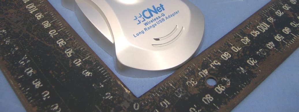
IIO-CUA854
Oct 30, 2007Wireless-G Long Range USB Adapter with Antenna
Equipment Class
DTS - Digital Transmission System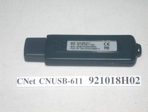
IIO-0343UD
Nov 18, 200311Mbps WLAN USB Dongle
Equipment Class
DTS - Digital Transmission System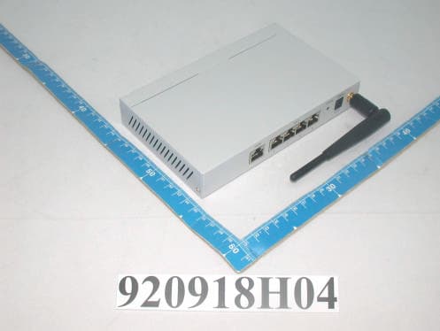
IIO-CNBR914W
Nov 03, 2003Wireless Router
Equipment Class
DTS - Digital Transmission System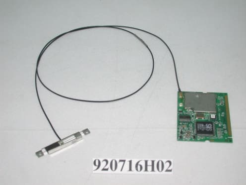
IIO-0328MP
Oct 21, 2003Wireless MiniPCI Module
Equipment Class
DTS - Digital Transmission System
IIO-0252WLAP
Jan 13, 200311Mbps Wireless Access Point
Equipment Class
DTS - Digital Transmission System