IP92K1VLaw Enforcement Surveillance Voice Transmitter
Tactical Technologies Inc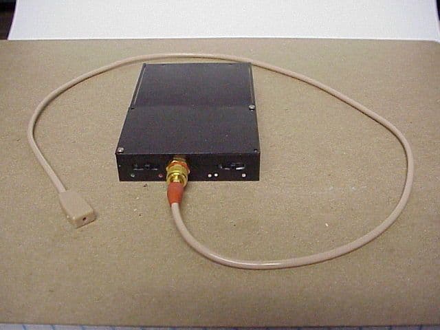
Click to zoom
Application Details
- Equipment Class
- LMS - Part 90 Location & Monitoring Transmitter
- Date of Grant
- Oct 16, 2000
- Application Purpose
- Original Equipment
- Date of Application
- Aug 29, 2000
- Equipment Note
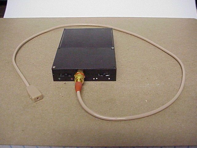
- Law Enforcement Surveillance Voice Transmitter
- Frequency Range
- 150.00000000 - 174.00000000
- Company
- Tactical Technologies Inc
- Country
- United States
Documents & Files
Document Text
Text extracted from the exhibit documents filed with the FCC. Open a document above to read the original.
Users Manual
CST2001/V SYNTHESIZED VOICE TRANSMITTER OPERATING INSTRUCTIONS © 2000 by Tactical Technologies Inc CST-2001 Series Covert Voice Transmitter DESCRIPTION The Tactical Technologies Inc. Model CST-2001/V series is a 1 or 2 channel 250 mW VHF-FM synthesized voice transmitter. The transmitter utilizes 4 "AA" Alkaline Batteries for its power supply, and is designed to utilize a specially built combined microphone/antenna unit. The CST- 2001 is programmed via an open serial port on an IBM compatable PC. The transmitter's firmware is compatable with ANY vintage IBM compatable PC's communications program - such as Hyperterminal or Terminal. The supplied instructions are for the Window 95 or 98 operating systems. BATTERY INSTALLATION 1.) Remove battery cover off unit by gently sliding the battery compartment cover down and away from the transmitter housing. Slight pressure may be needed to release the small dimples found near the bottom of the cover. 2.) Install 4 each standard AAA Alkaline batteries - Make sure you observe polarity as indicated inside battery compartment. 3.) Replace battery cover. Be sure to insert both sides of cover into the grooves on each side of the battery compartment. Cover slides easily up towards the top of the housing. NOTE: It is important to keep the cover aligned perpendicular with the transmitter housing when removing or replacing it. Slide Lid -------- > TRANSMITTER OPERATION 1.) CST-2001 comes with a single external, integral microphone/antenna component. Install microphone/ antenna to its appropirate connector on top of transmitter. The four pin connector is keyed for proper installation. Be sure to lock down the connector by twisting the screw ring clockwise until it snugs up to the panel connector. DO NOT OVERTIGHTEN. 2.) Select frequency to operate on by positioning frequency select slide switch: Single white O is frequency 1 Double white OO is frequency 2. 3.) Turn on/off switch to ON position Red O is OFF Green O is ON 4.) Test Operation using appropriate receiver. F1 F2 OFF ON INSTALLING YOUR SOFTWARE 1.) The computer program supplied to install the frequencies into your CST-2001 transmitter is a module written for Microsoft's Hyper- Terminal. HyperTerminal is supplied with Windows 95 and 98. If HyperTerminal is installed, you can proceed. If you have not installed this program onto your computer, please do so at this time. Installing HyperTerminal: a.) Select "START" from the Windows Task Bar b.) Select "Settings" - "Control Panel" from the Start Menu c.) Select "Add/Remove Programs" from the Control Panel d.) Select the "Windows Setup" tab at the top of the window e.) Double-click on "Communications" in the 'components' window. f.) Click the box next to "HyperTerminal". This puts an X in the box. g.) Click "OK" at the bottom of the window. h.) Click "OK" at the bottom of the new window. i.) Follow the on - screen insturctions about insterting you Windows Installation disks or CD. 4.) Install the HyperTerminal TTI Transmitter Programming Module: a.) Insert the supplied 3 1/2 inch floppy disk into you computer's disk drive. b.) Select "START" from the Windows Task Bar. c.) Select "RUN" from the Start Menu d.) Type "a:\setup" in the white bar e.) Select "OK" f.) Follow the on screen insturctions. g.) Remove disk when finished. PROGRAMING YOUR FREQUENCIES 1.) Connect the 2001 program- ming cable to the top of the transmitter via the round four pin connector. This connector is keyed for proper installation. Be sure to lock down the connector by twisting the screw ring clockwise until it snugs up to the panel connector. DO NOT OVERTIGHTEN. 2.) Connect the D style 9 pin female connector to an open serial port on your IBM compatable computer. If your computer's serial port is a 25 pin connector, you will need to use a DB25 to DB9 serial adaptor (not included). 3.) Start the "TTI Transmitter Programming" software by clicking it's icon located on the Windows Desktop. 4.) You must know the number of the Serial (Com) Port you have attached the transmitter to. The software comes ready to work with Com 1. If you are using Com 2, 3, or 4, you must perform the following: a.) Select "File" - "Properties" from the HyperTeminal Task Bar b.) From the "Phone Number" tab, select your Com Port in the IMPORTANT: 1.) If computer interface is not COM 1, you must select the correct Com port as described in the instruction. 2.) If you only program one frequency - program it into BOTH channels. 3.) The separation between the two transmit channels must be: Greater than or equal to 12.5 kHz 4.) Frequencies must be in 12.5 kHz steps. Your frequency must end in any of the following configura- tions: xxx.0000 xxx.1250 xxx.2500 xxx.3750 xxx.5000 xxx.6250 xxx.7500 xxx.8750 5.) The transmitter must be ON in order to program it. 6.) Turn OFF the transmitter when finished programming. OPERATING NOTES: 1.) Microphone/Antenna combination should always be kept vertical for best operation. 2.) Always use fresh batteries at the beginning of each operation. "Connect Using" pull down menu. Select the "Direct to Com ___" line that corrolates to your Com Port. c.) Select "OK" from the bottom of the window d.) Your Com Port selection is automatically saved. 5.) Turn ON your Transmitter. At this time, the transmitter will report its serial number and the frequencies programmed into it onto the HyperTerminal screen. 6.) Entering your frequencies is very easy. Just remember to use all lower case letters, and follow the same letter/punctuation/and space sequence that the transmitter reported to you on the screen. For the first frequency, you start by entering f1=. For the second frequency, you start by entering f2=. If at any time you make a mistake, you simply backspace to erase and type again. The program will also tell you if you have made an erroneous entry by reporting invalid as a response. If you want to see what frequencies are in the transmitter, type fv, for 'frequency validate'. Your frequency en…
Text truncated - open the document above for the full version.
Operational Description
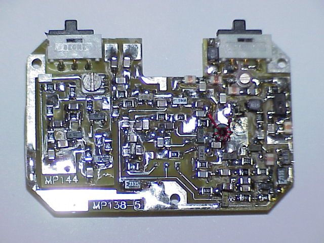
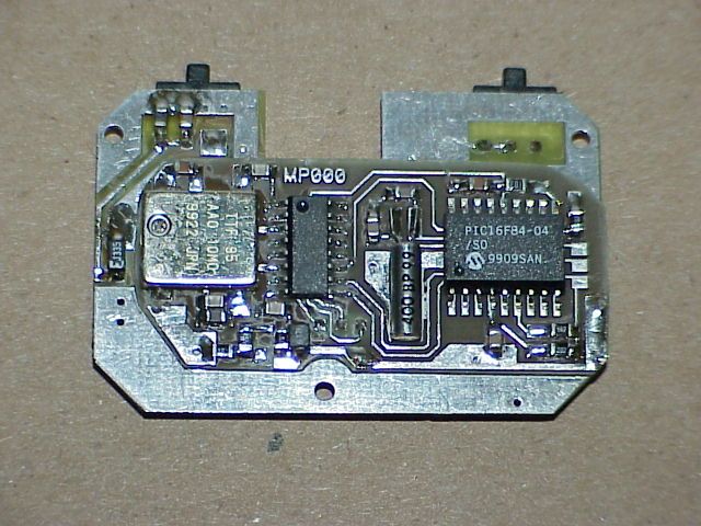
CST-2001/V FCC ID# IP92K51/V S/N 136 Two Channel Synthesized Transmitter Frequency Range 154 - 174 Mhz Power Output 250 mw I.C. and Transistor Discription: U1.................3.5 Volt regulator.......Toko TK11435CT-ND U2.................10Mhz 2.5ppm Reference...Temex TTF95AA010MHZ U3.................PLL......................Nat.Semi. 1501A U4.................Micrcontroller...........Micrchip 16F84/04 U5.................4 Mhz Xtal............... Q1.................FET......................Silconix 2N7000 Q2.................PNP......................Mot. 2N2907 Q3,Q4,Q5...........RF NPN......................Mot. BFR92A Q6.................RF NPN......................Nec. 46134 Q7,Q8,Q9,Q10.......AUDIO NPN...................Mot. 2N5088 RF Circuit Discription: The Microcontroller (U4) has 2 factory programmed frequencies 154 - 174 Mhz. The clock frequency of the microcontroller is 4 Mhz. The microcontroller sends data to the Phase Lock (U3), which converts the data into a dc voltage. This voltage is applied to the varactor which moves the oscillator (Q4) frequency to programmed frequency. The oscillator output is injected into the buffer (Q3), the buffered output is fedback to the PLL (U2) and the RF pre-amp (Q5). When the oscillator is at the desired frequency the PLL lock detect output turns ON the N-Channel FET (Q1) which turns on the PNP transistor (Q2) and applies voltage to the pre-amp and the final amp (Q6). The harmonic output of (Q6) is attenuated by the low pass filter. Audio Circuit Description: The microphone signal is amplified by (Q9 and Q10). The pre- emphasis is handled by the RC combinations of both audio amplifiers. The low pass filter (Q7) attenuates the audio frequencies after 2700 Hz. THhe audio from the low pass filter is converted to a dc voltage, this voltage turns ON the AGC transistor (Q8) which shorts the audio from the microphone to ground to prevent over deviation. The varable resistor controls the amount of deviation to the varactor. Antenna/Microphone Description: The antenna and the microphone are combined together through a matching circuit. The 1.8 uh inductors isolates the RF from the audio section. The 100 ohm resistor and 18 pf capacitor matches the transmitter low pass filter to the antenna. Computer interface Description: The microcontroller has a 2 wire interface with the computer. When the program cable is connected to the transismitter and the computer this disables the transmitter and puts the microcontroller in program mode. The data from the computer is converted in a hex number and stored in EE of the microcontroller.
Parts List/Tune Up Info
TUNING PROCEDURES FOR THE CST-2001/V The factory has programmed f1 to 154.0000 MHz and f2 to 174.0000 MHz. 1. Apply power to the transmitter 6.0 Vdc 2. Connect a coax cable to the 50 ohm test point, and place a 30 Dbm pad in series with a spectrum analyzer. 3. Turn the transmitter ON in the f2 channel position, monitor the supply current. 4. Measure the voltage at the junction of R12 and R13, by compressing the oscillator coil (L2) adjust the voltage to 3.25 volts. 5. Monitor the frequency of the transmitter with a frequency counter. The frequency should be 174.000000 MHz. Adjust the reference (X2) to the above frequency +/- 100 hz. 6. Monitor the power output with a watt meter (power output should be 250 mw +/- 1 Dbm.) @ 130 ma. 7. Adjust C34 while in f2 to reduce the second harmonic of the transmitter to 55 dbc maintaining 250 mw. 8. Slide the switch to f1 the frequency should read 154.000000 MHz +/- 100 Hz. The voltage at the junction of R12 and R13 should be 1.2 volts. Monitor the second harmonic with the spectrum analyzer, the second harmonic should be > 44 Dbc. 9. Monitoring the frequency with a modulation meter, whistle into the microphone and adjust R22 to 2.8 kHz deviation on f2 (174.0000 MHz).
Parts List/Tune Up Info
Bill of Materials CST-2001/V TACTICAL TECHNOLOGIES INC Quantity Type Value Ref Designators ======================================================================== 4 1Q Q7,Q8,Q9,Q10 1 2F Q2 3 3.3UF C2,C9,C28 1 4.0 MHZ X1 1 6T/28 L2 1 6.8UF C14 1 7X Q5 1 10 C34 1 10K R22 1 10UF C23 1 16F84 U1 2 100 R14,R19 3 102 R6,R15,R18 1 103 R45 1 103 R7 1 104 R9 6 104 R10,R27,R28,R31,R34,R35 1 121 R21 1 151 R25 1 153 R17 1 154 R23 1 180 R42 2 202 R39,R46 2 202 R36,R38 1 221 R3 1 223 R44 1 223 R24 4 242 R26,R30,R33,R37 2 272 R29,R32 1 301 R41 1 301 R43 1 331 R2 2 332 R12,R13 1 333 R4 1 333 R11 1 393 R8 1 470 R5 1 471 R1 1 472 R20 1 562 R40 1 702 Q1 1 752 R16 1 A0T C15 1 A1 C20 1 A2 C21 3 A2N L1,L4,L8 1 A3 C57 2 A4 C55,C58 1 A5 C35 1 A6 C46 3 A7 D1,D2,D3 1 C1 C17 2 E1 C51,C52 1 E1N L10 2 E2N L5,L9 2 G1 C24,C33 1 J1 C26 1 J5 C4 3 J6 C8,C36,C50 1 K1 C25 1 L1 C19 1 LMX1501A U2 2 M4E V1,V2 8 N6 C12,C18,C29,C37,C38,C39, C42,C43 2 P2 Q3,Q4 1 QS Q6 1 S1 C3 2 S1N L3,L7 8 S2 C5,C7,C13,C22,C27,C31,C53, C54 1 S2 C30 1 S3 C40 1 S4 C49 5 S4 C10,C41,C44,C45,C47 1 S5 C11 2 SW SW1,SW2 1 T35 VR1 1 TCXO X2
Schematics
101 R1 8 470PF C7 470PF C1 3 3,3UF C1 2 10 R1 4 470PF C5 300 R4 3 C3 1 470 L9 150NH R4 4 22K R4 0 5.6K S? R4 5 1OK C5 4 470P C5 8 .047 C5 5 .01 C4 9 .047 R3 9 2K L8 .47UF C1 0 15N L1 0 A7 D1 1K R6 18 R4 2 300 R4 1 470P C5 3 15 C5 2 4MHZ X1 15 C5 1 330 R2 47PF C3 10K R7 220 R3 BFR92 Q3 L2 10PF C2 0 10UF C2 3 470PF C2 2 VAL R? 47N L7 100N L8 47N L3 24 C2 5 QS Q6 1.5K R2 8 150NH L? 100NH L4 18PF C2 4 18PF C3 3 C3 4 10 A7 D2 10 R1 9 22PF C2 6 2.2UF C3 6 .1UF C3 5 3.3UF C8 100NH L1 7X Q5 470 R5 BFR92 Q4 1K R1 5 15PF C1 7 27PF C1 9 3.5V VR1 33K R4 702 Q1 .22UF C4 2K R4 6 39K R8 Q2 MMBT2907 S? .001 C5 7 100PF C2 1 M4 E V2 M4 E V1 .5PF C1 5 33K R1 1 .47UF C1 1 470 C3 0 R1 0 100K 3.3K R1 3 3.3K R1 2 470 R1 R9 100K C2 9 3.3UF C2 8 3.3UF C9 3.3UF R2 1 331 C2 3.3UF C1 4 6.8UF X2 (SH 2) MIC +3.5 SERIAL IN PGM F1 / F2 11 U1 16F84 6 21 5 16 15 14 4 17 9 8 LE DATA CLK 9 10 11 +3.54 8 5 6 +BAT 7 3 10 1 AUDIO (SH 2) 10MHZ U2 LMX1501A ANT/ MIC A/ M- RETURN CONN CST 2001- V TX SECTION 2001- TX ABCD 4 3 2 1 DCBA 1 2 3 4 A3 RevNum ber Ti t l e Size Da t e Filenam e Dr a wn b y ofSheet
Schematics
C3 7 3.3UF 10K R2 2 3.3UF C4 2 .047 C4 1 .0047 C4 0 150 R2 5 Q7 MMBT5088 2.7K R2 9 2.7K R3 2 .047 C4 5 Q8 MMBT5088 2.4K R3 3 1.UF C4 6 2K R3 6 Q1 0 MMBT5088 100K R3 4 100K R3 5 .047 C4 7 100K R2 7 R3 7 2.4K 3.3UF C4 3 2K R3 8 100K R3 1 Q9 MMBT5088 .047 C4 4 R3 0 2.4K R2 6 2.4K C3 8 3.3UF R2 8 100K C3 9 3.3UF D3 A7 R2 4 22K R2 3 15OK 2001- AUD CST 2001- V AUDIO (SH 1) +3.5 (SH 1) AUDIO MIC 22 A (SH 2) ABCD 4 3 2 1 DCBA 1 2 3 4 A3 RevNum ber Ti t l e Size Da t e Filenam e Dr a wn b y ofSheet
Test Report
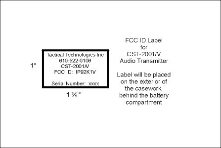
Part 90 Testing CST-2001/V Synthesized Voice Transmitter FCC ID: IP92K1V Performed by Tactical Technologies Inc. 1701 Second Ave Folsom, PA 19033 610-522-0106 August 24, 2000 The audio frequency response, low pass filter test, occupied bandwidth, and frequency stability in this application for FCC Type Certification have been performed under my direct supervision. To the best of my knowledge these tests were conducted in accordance with the procedures outlined in Part 2 and Part 90 of the Commission's Rules and Regulations. I am presently employed by Tactical Technologies Inc. in Folsom, Pennsylvania as a Design Engineer. My prior experience consists of 10 years of designing and testing communications products in the VHF portion of the spectrum. Sincerely, Jeffrey N. Olson Engineer Tactical Technologies Inc. A. INTRODUCTION The following data are submitted in connection with this Application for Type Certification in accordance with Part 2, Subpart J, and Part 90, Subparts B,D, and I of the FCC Rules and Regulations. B. INFORMATION REQUIRED BY PART 2 - Paragraph 2.981 This section provides data as required by the following Paragraphs: 2.983,2.985,2.987,2.989,2.993,2.995,2.997,2.999 and 2.1003. 2.983 (a) See Form 731 2.983 (b) See Form 731 2.983 (c) Quantity production is anticipated 2.983(d)(1) - (d)(3) See Form 731 2.983)d)(4) The maximum transmitter power output is .25 Watt. (5) RF final amplifier: At 6.00 Vdc and .08 Adc, Po = .25W. (6) The function of each active device is included in the exhibits section of this application. (7) Complete circuit diagrams are included. (8) Operating instructions are included in the exhibits section of this application. (9) Complete tune-up procedures are included in the exhibits section of this application. (10) A description of all circuitry and devices provided for determining and stabilizing frequency is included in the exhibits section of this application. (11) A description of any circuits and devices employed for suppression of spurious radiation, for limiting modulation, and for limiting power in the exhibits section of this application. (12) N/A 2.983(e) The data required by Paragraphs 2.985 through 2.987, inclusive, measured in accordance with the procedures contained in Paragraph 2.999, are included in Section E of this application. (f) A photograph or drawing of the equipment identification plate or label showing the information to be placed thereon is included in the exhibits section of this application. (g) The required 8 x 10 photographs revealing equipment construction and layout are included in the exhibits section of this application. (h) N/A (i) N/A 2.997 The frequency spectrum investigation for spurious emissions per Paragraphs 2.991 and 2.993 include from the lowest frequency within the transmitter to at least the 10th harmonic of the carrier frequency. 2.999 The measurement procedures employed are in accordance with the requirements set forth in Paragraph 2.947. 2.1003 The identification label complies with the requirements of this Paragraph and Paragraph 2.925. ̋ ̋ ̋ C. SUBMISSION OF EQUIPMENT FOR TESTING - Paragraph 2.943 ̋ Upon request, the test sample will promptly be made available ̋ by Radiation Science Inc. D. DESCRIPTION OF MEASUREMENT FACILITIES - Paragraph 2.947 The open-field tests were performed on the 3 meter range maintained by Radiation Science Inc. Complete description and measurement data have been placed on file with the Commission. E. TEST DATA This section contains results of measurements required by Parts 2 and 90 of the rules. Data are presented in tabular and/ or graphical form, and measurement procedures are described within the text of each reported test. The test sample operated on 154.6000 MHz. 1. RF POWER OUTPUT - Paragraphs [2.985,2.983(d)(5),90.205(b)] Measurements pertaining to the power output of the transmitter were performed by the manufacturer. To the best of my knowledge, these tests were conducted in accordance with the procedures outlined in Parts 2 and 90 of the Commissions Rules and regulations. The data presented on Table 1 demonstrates compliance with the appropriate technical standards. 2. MODULATION CHARACTERISTICS - Paragraph [2.987(a), 90.211] Measurements pertaining to the modulation characteristics were performed by the manufacture. To the best of my knowledge, these tests were conducted in accordance with the procedures outlined in Parts 2 and 90 of the Commission's Rules and regulations. The data presented on figures 1 and 2 demonstrates compliance with the appropriate technical standards. 3. OCCUPIED BANDWIDTH - Paragraphs [2.989(c)(1), 90.209(c)] Figures 3 and 4 contain pictures taken from a Hewlett Packard 8558B Spectrum Analyzer. The transmitter was modulated with a sine wave tone at 2500 Hz at a level 16 dB above the required to produce 50% modulation at the frequency maximum response. Paragraph 90.209(c) requires that the mean power of emissions shall be attenuated below the mean output power of the transmitter by the following amounts. (a) On any frequency removed from the assigned frequency by more than 50% but not more than 100% of the authorized bandwidth (at least 25db) (b) On any frequency removed from the assigned frequency by more than 100% but not more that 250% of the authorized bandwidth (at least 35db). (c) On any frequency removed from the assigned frequency by more than 250% of the authorized bandwidth [at least 50 + log(w) dB or 80 dB, whichever is the lesser attenuation]. ̋ ̋ ̋ ̋ 4. SPURIOUS EMISSIONS AT THE 50 OHM TEST POINT ON THE TRANSMITTER [2.991, 90.209(c)] The transmitter was modulated per paragraph 2.989(c)(1). The spectrum was checked with the spectrum analyzer from 10 MHz to the 10th harmonic of the carrier frequency. Observed emissions not reported are attenuated more than 20 dB below the permissible value of 44 dB, i,e., 50 + log (.25W) = 44 dB given by Section 90.209(c)(3). The data in Table 1 verifies that the test sample complies with Paragraph…
Text truncated - open the document above for the full version.
Test Report
Part 90 Testing CST-2001/V Synthesized Voice Transmitter FCC ID: IP92K1V Performed by Tactical Technologies Inc. 1701 Second Ave Folsom, PA 19033 610-522-0106 August 24, 2000 The audio frequency response, low pass filter test, occupied bandwidth, and frequency stability in this application for FCC Type Certification have been performed under my direct supervision. To the best of my knowledge these tests were conducted in accordance with the procedures outlined in Part 2 and Part 90 of the Commission's Rules and Regulations. I am presently employed by Tactical Technologies Inc. in Folsom, Pennsylvania as a Design Engineer. My prior experience consists of 10 years of designing and testing communications products in the VHF portion of the spectrum. Sincerely, Jeffrey N. Olson Engineer Tactical Technologies Inc. A. INTRODUCTION The following data are submitted in connection with this Application for Type Certification in accordance with Part 2, Subpart J, and Part 90, Subparts B,D, and I of the FCC Rules and Regulations. B. INFORMATION REQUIRED BY PART 2 2.1003(a) See Form 731 2.1033(b) N/A 2.1003(c)(1) The full name and address of the applicant and manufacture for certification is: Tactical Technologies Inc. 1701 Second Ave. P.O. Box 91 Folsom, Pa. 19033 (2) The FCC Identifier of this device is IP92K1V (3) Operating Instructions are included in the Exhibits. (4) Emission: NBFM Voice – 11K2F3 Emission Calculations are included in the Exhibits. (5) Frequency Range 154 – 174 Mhz (6) Output Power of the device is 250mw. @ 6 Volts (7) Maximum Power Rating is 250mw. (8) All of the Transmitters sections run off of regulated +3.5 Volts, and the RF Final transistor runs on 6 Volts. (9) Tune up procedure are included in the Exhibits. (10) Schematics are included in the Exhibits. (11) A drawing of the equipment identification label are included in the Exhibits. (12) Photographs of the internal and external construction of the device are included in the Exhibits. (13) N/A (14) Test Data required by Part 2.1046 through 2.1057, inclusive, is measured in accordance with the procedure in Part 2.1041. (15) N/A (16) N/A (17) N/A C. SUBMISSION OF EQUIPMENT FOR TESTING - Paragraph 2.943 Upon request, the test sample will promptly be made available by Radiation Science Inc. D. DESCRIPTION OF MEASUREMENT FACILITIES - Paragraph 2.947 The open-field tests were performed on the 3 meter range maintained by Radiation Science Inc. Complete description and measurement data have been placed on file with the Commission. E. TEST DATA This section contains results of measurements required by Parts 2 and 90 of the rules. Data are presented in tabular and/ or graphical form, and measurement procedures are described within the text of each reported test. The test sample operated on 154.6000 MHz. 1. RF POWER OUTPUT - Paragraphs [2.1046(a),2.1033(c)(8),90.205(d)] Measurements pertaining to the power output of the transmitter were performed by the manufacturer. To the best of my knowledge, these tests were conducted in accordance with the procedures outlined in Parts 2 and 90 of the Commissions Rules and regulations. The data presented on Table 1 demonstrates compliance with the appropriate technical standards. 2. MODULATION CHARACTERISTICS - Paragraph [2.1047(a), 90.211(a)] Measurements pertaining to the modulation characteristics were performed by the manufacture. To the best of my knowledge, these tests were conducted in accordance with the procedures outlined in Parts 2 and 90 of the Commission's Rules and regulations. The data presented on figures 1 and 2 demonstrates compliance with the appropriate technical standards. 3. OCCUPIED BANDWIDTH - Paragraphs [2.1049, 90.211(a)] Figures 3 and 4 contain pictures taken from a Hewlett Packard 8558B Spectrum Analyzer. The transmitter was modulated with a sine wave tone at 2500 Hz at a level 16 dB above the required to produce 50% modulation at the frequency maximum response. Paragraph 90.210(d) requires that the mean power of emissions shall be attenuated below the mean output power of the transmitter by the following amounts. (a) On any frequency removed from the center of the authorized bandwidth f0 to 5.625 khz removed from f0; Zero db. (b) On any frequency removed from the center of the authorized bandwidth by a displacement frequency (fd in khz) of more than 5.625 khz but no more than 12.5 khz. At least (fd – 2.88khz)db. (c) On any frequency removed from the center of the authorized Bandwidth by a displacement frequency (fd in khz) of no more than 12.5 khz. At least 50 + log(P) or 70db, whichever is the lesser attenuation. ̋ ̋ ̋ ̋ 4. SPURIOUS EMISSIONS AT THE 50 OHM TEST POINT ON THE TRANSMITTER [2.1053, 90.209 Emission Mask D] The transmitter was modulated per paragraph 2.1053 The spectrum was checked with the spectrum analyzer from 10 MHz to the 10th harmonic of the carrier frequency. Observed emissions not reported are attenuated more than 20 dB below the permissible value of 44 dB, i,e., 50 + log (.25W) = 44 dB given by Section 90.209. The data in Table 1 verifies that the test sample complies with Paragraph 90.209(c)(3). TABLE 1 CONDUCTED SPURIOUS EMISSIONS DATA EMISSION EMISSION FCC FREQUENCY LEVEL LIMIT (MHz) (dBc) (dBc) 154.6 REFEERENCE +24 dBm 44 309.2 -52 44 463.8 -58 44 618.4 -75 44 773.0 >-75 44 927.6 >-75 44 1082.2 >-75 44 1236.8 >-75 44 1391.4 >-75 44 1546.0 >-75 44 5. FIELD STRENGTH OF SPURIOUS RADIATION - Paragraphs [2.1053,90.209] Measurements were made on the three meter range maintained by Radiation Science Inc. to quantify spurious emission level that] are radiated directly from the cabinet, control circuits, power leads and intermediate circuit elements under normal conditions of installation and operation. Particular attenuation was paid to harmonics of the carrier frequency as well as those frequencies removed from the carrier by multiples of the oscillator frequency. Data is submitted in Table 2 showing the magnitude of harmonics and other spurious emiss…
Text truncated - open the document above for the full version.
Test Report
INPUT SIGNAL LEVEL VS. DEVIATION CST-2001/V FCC ID # IP92K1V 0.0% 20.0%40.0%60.0%80.0% 100.0%120.0% 100Hz 300Hz 500Hz 750Hz 1000Hz 1500Hz 2000Hz 2500Hz 3000Hz 4000Hz 5000Hz FREQUENCY Series 1 = -60Dbm Series 2= -50Dbm Series 3 = -40Dbm Series 4 = -30Dbm DEVIATION Series1Series2Series3Series4
Contact Information
Applicant
Richard B Snyder(President)
Technical Specifications
| # | Rule Parts | Frequency Range | Power Output | Emission | Tolerance |
|---|---|---|---|---|---|
| 1 | 90 | 150 MHz - 174 MHz | 250.00 mW | 11K2F3E | 2.5000000000 ppm |
Other Applications from Tactical Technologies Inc
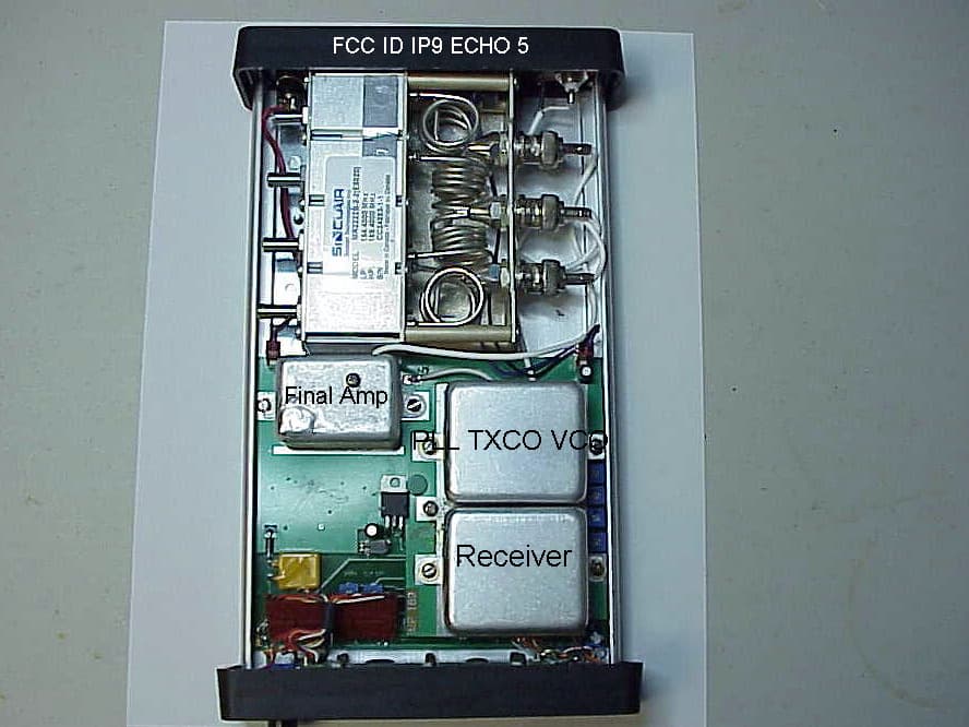
IP9ECHO5
Aug 21, 2005Repeater
Equipment Class
TNB - Licensed Non-Broadcast Station Transmitter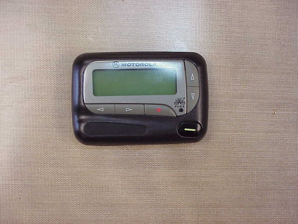
IP9801VI
Jun 22, 2005Synthesized VHF Surveillance Voice Transmitter
Equipment Class
TNT - Licensed Non-Broadcast Transmitter Worn on Body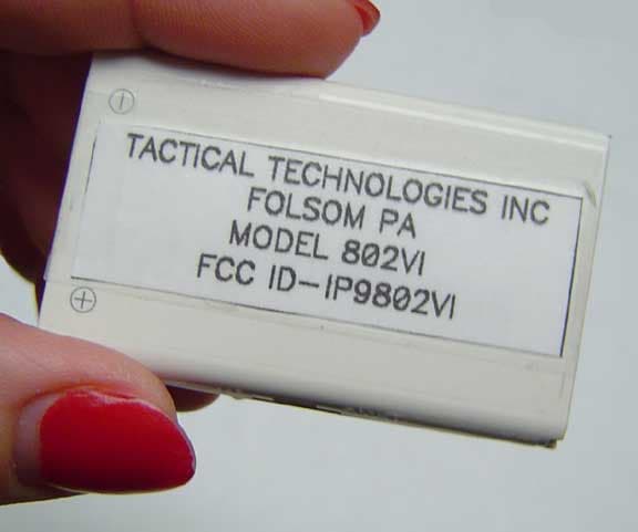
IP9802VI
May 05, 2005Synthesized VHF Surveillance Voice Transmitter
Equipment Class
TNT - Licensed Non-Broadcast Transmitter Worn on Body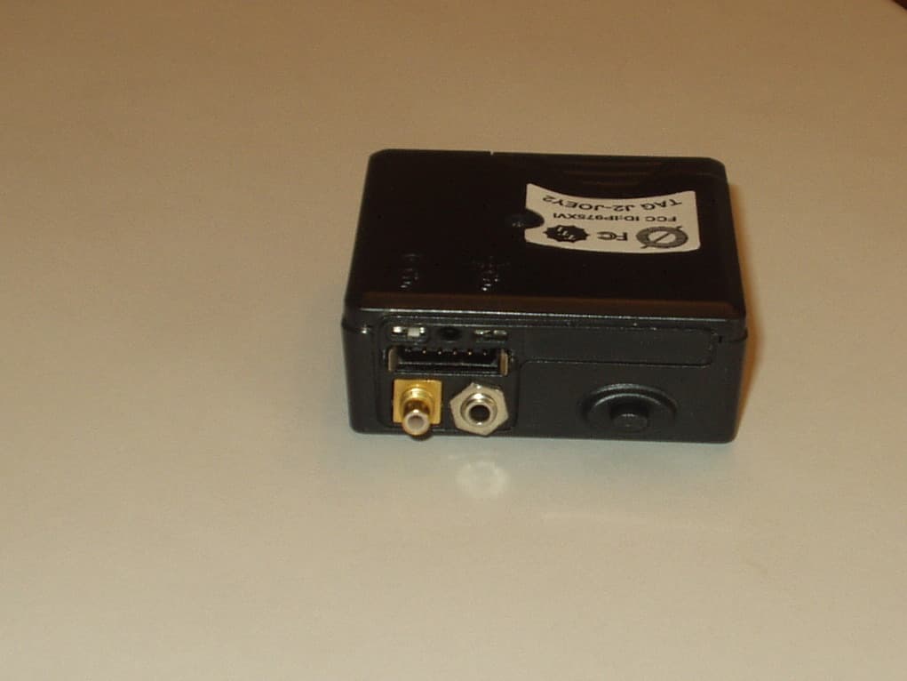
IP975XVI
Mar 28, 2005Synthesized VHF Surveillance Voice Transmitter
Equipment Class
TNT - Licensed Non-Broadcast Transmitter Worn on Body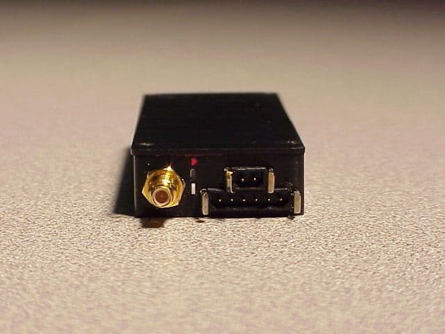
IP9751V
Dec 01, 2002Law Enforcement Surveillance Transmitter
Equipment Class
LMS - Part 90 Location & Monitoring Transmitter