IP92K5VSurveillance Voice Transmitter
Tactical Technologies Inc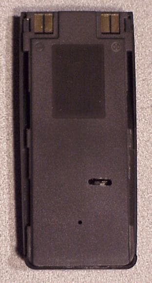
Click to zoom
Application Details
- Equipment Class
- LMS - Part 90 Location & Monitoring Transmitter
- Date of Grant
- Oct 31, 2001
- Application Purpose
- Original Equipment
- Date of Application
- Sep 04, 2001
- Equipment Note
- Surveillance Voice Transmitter
- Frequency Range
- 150.00000000 - 174.00000000
- Company
- Tactical Technologies Inc
- Country
- United States
Documents & Files
Document Text
Text extracted from the exhibit documents filed with the FCC. Open a document above to read the original.
Users Manual
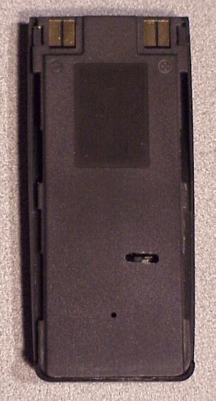
CST-2005/V Crystal Controlled VOICE TRANSMITTER OPERATING INSTRUCTIONS © 2001 by Tactical Technologies Inc Tactical Technologies Inc 1701 Second Ave PO Box 91 Folsom, Pennsylvania 19033 USA TEL: 610-522-0106 FAX: 610-522-9430 CST-2005/V Covert Voice Transmitter DESCRIPTION The Tactical Technologies Inc. Model CST-2005/V series is a 1 channel 100 mW VHF-FM crystal controlled voice transmitter disguised inside a Nokia 5000/6000 series cell phone battery housing. The transmitter utilizes internal LithiumIon rechargeable batteries for its power supply, and is designed to be used as a stand alone transmitter, or it can be installed on the back of a Nokia 5000/6000 series cellphone. BATTERY CARE The internal batteries should be recharged using a Nokia 5000/6000 series cellphone battery charger. Initial charging should be for a period of 5 hours. Thereaf- ter, a full charge should take approximately 3 hours. The battery may be charged in a stand-alone drop-in charger, or it may be charged while attached to a Nokia Cellphone. TRANSMITTER OPERATION 1.) CST-2005/V comes with a recessed ON/OFF switch located on the flat side of the transmitter housing. 2.) Slide switch toward the EDGE of the transmitter to turn the unit ON. 3.) Test Operation using appropriate receiver. 4.) Slide switch toward the CENTER of the transmitter to turn the unit OFF. The transmitter is equipped with an internal microphone and antenna. OPERATING NOTES: 1.) Do not immerse the unit in water. 2.) Always fully charge the unit before any operation. 3.) Make sure the On/Off switch is in the OFF position when your operation is complete. OFF ON On/Off Switch Location:
Cover Letter(s)
September 6, 2001 Federal Communications Commission Equipment Authorization Division RE: Request for Confidentiality, FCC ID IP92K5V This letter is a request to hold the following documents pertaining to the application for FCC Type Certification for IP92K5V as confidential and to withhold them from public disclosure. This request is concurrent with the FCC rules (section 0.457(d) and section 0.459) and the Freedom of Information Act (section 0.552(b)(4)). The documents are: 1.) All schematic diagrams 2.) All circuit descriptions 3.) All parts lists 4.) All circuit block diagrams 5.) All internal photographs Public disclosure of these pieces of design information would put Tactical Technologies Inc. at a substantial disadvantage competitively. Tactical Technologies Inc. does not make the above information available to the general public. Thank you very much for your attention to this. Sincerely, Jeffrey Olsen Engineer Tactical Technologies Inc
Cover Letter(s)
October 22, 2001 Federal Communications Commission Equipment Authorization Division RE: Request for Confidentiality, FCC ID IP92K5V This letter is a request to hold the following documents pertaining to the application for FCC Type Certification for IP92K5V as confidential and to withhold them from public disclosure. This request is concurrent with the FCC rules (section 0.457(d) and section 0.459) and the Freedom of Information Act (section 0.552(b)(4)). The documents are: 1.) All schematic diagrams 2.) All circuit descriptions 3.) All parts lists 4.) All circuit block diagrams Public disclosure of these pieces of design information would put Tactical Technologies Inc. at a substantial disadvantage competitively. Tactical Technologies Inc. does not make the above information available to the general public. Thank you very much for your attention to this. Sincerely, Jeffrey Olsen Engineer Tactical Technologies Inc
Test Report
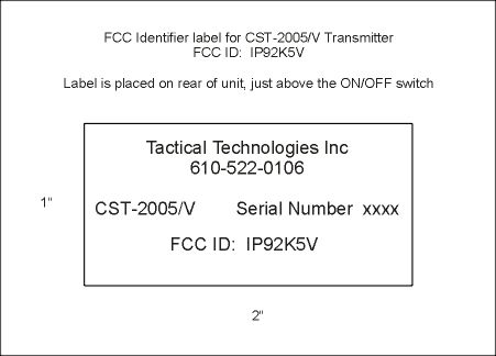
Part 90 Testing CST-2005/V Crystal Controlled Voice Transmitter FCC ID: IP92K5V Performed by Tactical Technologies Inc. 1701 Second Ave Folsom, PA 19033 610-522-0106 August 24, 2001 The audio frequency response, low pass filter test, occupied bandwidth, frequency stability, transient behavior, and modulation testing in this application for FCC Type Certification have been performed under my direct supervision. To the best of my knowledge these tests were conducted in accordance with the procedures outlined in Part 2 and Part 90 of the Commission's Rules and Regulations. I am presently employed by Tactical Technologies Inc. in Folsom, Pennsylvania as a Design Engineer. My prior experience consists of 10 years of designing and testing communications products in the VHF portion of the spectrum. Sincerely, Jeffrey N. Olson Engineer Tactical Technologies Inc. A. INTRODUCTION The following data are submitted in connection with this Application for Type Certification in accordance with Part 2, Subpart J, and Part 90, Subparts B,D, and I of the FCC Rules and Regulations. B. INFORM ATION REQUIRED BY PART 2 2.1003(a) See Form 731 2.1033(b) N/A 2.1003(c) (1) The full name and address of the applicant and manufacture for certification is: Tactical Technologies Inc. 1701 Second Ave. P.O. Box 91 Folsom, Pa. 19033 (2) The FCC Identifier of this device is IP92K5V (3) Operating Instructions are included in the Exhibits. (4) Emission: NBFM Voice – 11K2F3 Emission Calculations are included in the Exhibits. (5) Frequency Range 150 – 174 Mhz (6) Output Power of the device is 100mw. @ 3.6 Volts (7) Maximum Power Rating is 100mw. (8) All of the Transmitters sections run off of regulated +5.0 Volts, and the RF Final transistor runs on 5 Volts. (9) Tune up procedure are included in the Exhibits. (10) Schematics are included in the Exhibits. (11) A drawing of the equipment identification label is included in the Exhibits. (12) Photographs of the internal and external construction of the device are included in the Exhibits. (13) N/A (14) Test Data required by Part 2.1046 through 2.1057, inclusive, is measured in accordance with the procedure in Part 2.1041. (15) N/A (16) N/A (17) N/A C. SUBMISSION OF EQUIPMENT FOR TESTING - Paragraph 2.943 Upon request, the test sample will promptly be made available by Radiation Science Inc. D. DESCRIPTION OF MEASUREMENT FACILITIES - Paragraph 2.947 The open-field tests were performed on the 3 meter range maintained by Radiation Science Inc. Complete description and measurement data have been placed on file with the Commission. E. TEST DAT A This section contains results of measurements required by Parts 2 and 90 of the rules. Data are presented in tabular and/or graphical form, and measurement procedures are described within the text of each reported test. The test sample operated on 166.2250 MHz. 1. RF POWER OUTPUT - Paragraphs [2.1046(a),2.1033(c)(8),90.205(d)] Measurements pertaining to the power output of the transmitter were performed by the manufacturer. To the best of my knowledge, these tests were conducted in accordance with the procedures outlined in Parts 2 and 90 of the Commissions Rules and regulations. The data presented on Table 1 demonstrates compliance with the appropriate technical standards. 2. MODULATION CHARACTERISTICS - Paragraph [2.1047(a), 90.211(a)] Measurements pertaining to the modulation characteristics were performed by the manufacture. To the best of my knowledge, these tests were conducted in accordance with the procedures outlined in Parts 2 and 90 of the Commission's Rules and regulations. The data presented on figures 1 and 2 demonstrates compliance with the appropriate technical standards. 3. OCCUPIED BANDWIDTH - Paragraphs [2.1049, 90.211(a)] Figures 3 and 4 contain pictures taken from a Hewlett Packard 8558B Spectrum Analyzer. The transmitter was modulated with a sine wave tone at 2500 Hz at a level 16 dB above the required to produce 50% modulation at the frequency maximum response. Paragraph 90.210(d) requires that the mean power of emissions shall be attenuated below the mean output power of the transmitter by the following amounts: -- On any frequency removed from the center of the authorized bandwidth f0 to 5.625 khz removed from f0; Zero db. -- On any frequency removed from the center of the authorized bandwidth by a displacement frequency (fd in khz) of more than 5.625 khz but no more than 12.5 khz. At least (fd – 2.88khz)db. -- On any frequency removed from the center of the authorized Bandwidth by a displacement frequency (fd in khz) of no more than 12.5 khz. At least 50 + log(P) or 70db, whichever is the lesser attenuation. 4. SPURIOUS EMISSIONS AT THE 50 OHM TEST POINT ON THE TRANSMITTER [2.1053, 90.209 Emission Mask D] The transmitter was modulated per paragraph 2.1053. The spectrum was checked with the spectrum analyzer from 10 MHz to the 10th harmonic of the carrier frequency. Observed emissions not reported are attenuated more than 20 dB below the permissible value of 40 dB, i,e., 50 + log (.10W) = 40 dB given by Section 90.209. The data in Table 1 verifies that the test sample complies with Paragraph 90.209(c)(3). TABLE 1 CONDUCTED SPURIOUS EMISSIONS DATA EMISSION EMISSION FCC FREQUENCY LEVEL LIMIT (MHz) (dBc) (dBc) 166.2 REFEERENCE +20 dBm 40 332.4 -52 40 498.6 -58 40 664.8 -75 40 831.1 >-75 40 997.3 >-75 40 1163 >-75 40 1329 >-75 40 1495 >-75 40 1662 >-75 40 5. FIELD STRENGTH OF SPURIOUS RADIATION - Paragraphs [2.1053,90.209] Measurements were made on the three meter range maintained by Radiation Science Inc. to quantify spurious emission level that] are radiated directly from the cabinet, control circuits, power leads and intermediate circuit elements under normal conditions of installation and operation. Particular attenuation was paid to harmonics of the carrier frequency as well as those frequencies removed from the carrier by multiples of the oscillator frequency. Data is submitted in Table 2 showing the magnitude of ha…
Text truncated - open the document above for the full version.
Contact Information
Applicant
Richard B Snyder(President)
Test Firm
Radiation Sciences IncorporatedDaniel Signore
215-256-4133Fax: 215-256-0775
Technical Specifications
| # | Rule Parts | Frequency Range | Power Output | Emission | Tolerance |
|---|---|---|---|---|---|
| 1 | 90 | 150 MHz - 174 MHz | 100.00 mW | 11K2F3E | 5.0000000000 ppm |
Other Applications from Tactical Technologies Inc
IP9ECHO5
Aug 21, 2005Repeater
Equipment Class
TNB - Licensed Non-Broadcast Station Transmitter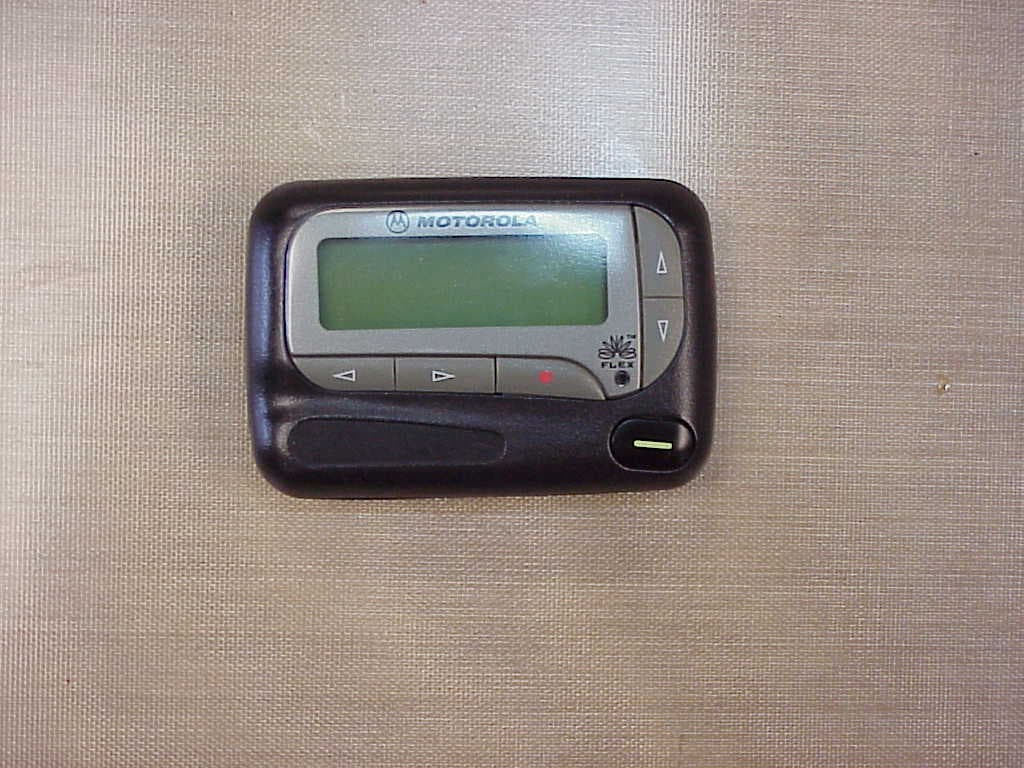
IP9801VI
Jun 22, 2005Synthesized VHF Surveillance Voice Transmitter
Equipment Class
TNT - Licensed Non-Broadcast Transmitter Worn on Body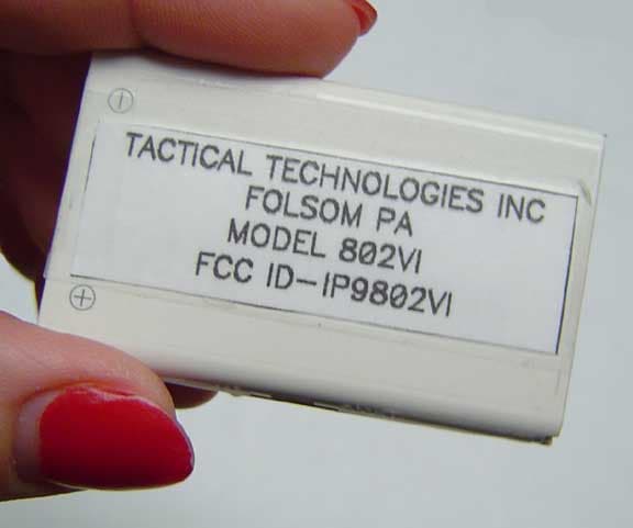
IP9802VI
May 05, 2005Synthesized VHF Surveillance Voice Transmitter
Equipment Class
TNT - Licensed Non-Broadcast Transmitter Worn on Body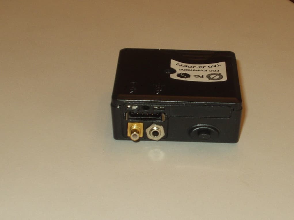
IP975XVI
Mar 28, 2005Synthesized VHF Surveillance Voice Transmitter
Equipment Class
TNT - Licensed Non-Broadcast Transmitter Worn on Body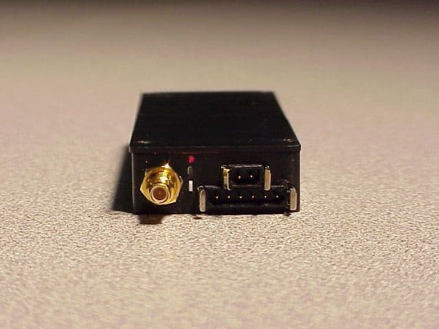
IP9751V
Dec 01, 2002Law Enforcement Surveillance Transmitter
Equipment Class
LMS - Part 90 Location & Monitoring Transmitter