IP9CST703Covert Surveillance Transmitter
Tactical Technologies Inc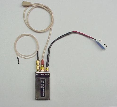
Click to zoom
Application Details
- Equipment Class
- LMS - Part 90 Location & Monitoring Transmitter
- Date of Grant
- Jan 30, 2001
- Application Purpose
- Original Equipment
- Date of Application
- Sep 28, 2000
- Equipment Note
- Covert Surveillance Transmitter
- Frequency Range
- 150.00000000 - 174.00000000
- Company
- Tactical Technologies Inc
- Country
- United States
Documents & Files
Document Text
Text extracted from the exhibit documents filed with the FCC. Open a document above to read the original.
Users Manual
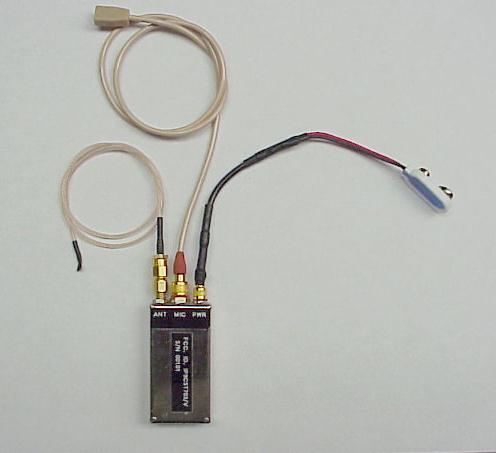
CST-703/V COVERT VOICE TRANSMITTER OPERATING INSTRUCTIONS © Tactical Technologies Inc CST-703/V COVERT VOICE TRANSMITTER DESCRIPTION The Tactical Technologies Inc. Model CST-703/V is a miniature one channel synthesized VHF Voice Transmitter capable of standard operation between 150 MHz and 174 MHz. Output power is vari- able; dependent upon variable input voltage. The 703 comes standard with an external antenna, internal microphone, external microphone connection, a programming cable, and various configu- rations of power connectors. The 703 can be installed in a wide variety of disguises. OPERATION 1.) Select desired input voltage vs. power output from the following chart: INPUT VOLTAGEOUTPUT POWER 6.0 VDCapprox. 1/4 watt 9.0 VDCapprox. 1/2 watt WARNING: Do not apply 12 VDC directly to this unit. A special regulator cable must be used. Any power supply (batteries, regulated supply, etc.) can be applied to the CST-703 with voltages that range from 6 volts DC to 9 volts DC. 2.) Connect the external antenna to the CST-703 by inserting the male end of the SMC type antenna connector on the transmitter to the female connector end on the bodywire antenna. Twist the connector clockwise to tighten (HAND TIGHT ONLY!). 3.) Determine which microphone configuration is best for your application: the internal microphone or the external microphone. a.) If the external microphone is desired, insert the male end of the locking mini-plug type connector on the microphone cable into the female connector found on the transmitter. Twist the cable end connector clockwise to tighten and lock down to the transmitter (HAND TIGHT ONLY). Once the external microphone is connected to the 703, the internal microphone is electronically disconnected and will not operate - eliminating any chance of the internal micro- phone interfering with the desired external unit. b.) If the internal microphone is desired, simply make sure the external microphone is disconnected from the 703. The internal microphone automatically becomes operational when the external microphone is disconnected. 4.) Connect the appropriate power lead to the transmitter. Insert the male end of the 4 pin mini type connector attached to the power cable into the female end found on the unit. Twist clockwise to tighten (HAND TIGHTEN ONLY!). NOTE: THE CST-703 IS REVERSE POLARITY PROTECTED, HOWEVER PLEASE BY SURE TO CONNECT THE + AND - LEADS TO YOUR POWER SUPPLY CORRECTLY FOR PROPER OPERATION OF THE TRANSMITTER. PAY PARTICULAR ATTENTION TO THE MARKINGS ON SMALL BATTERIES. WHEN USING THE FLYING LEAD CONNECTORS. THE BLACK LEAD IS NEGATIVE AND THE RED OR WHITE LEAD IS THE POSITIVE. 5.) Once power is applied to the transmitter, the unit is on and operating. To turn the unit off, simply disconnect the power. INSTALLING YOUR SOFTWARE 1.) The computer program supplied to install the frequencies into your CST-703 transmitter is a module written for Microsoft's Hyper- Terminal. Hyper-Terminal is supplied with Windows 95 and 98. If Hyper-Terminal is installed, you can proceed. If you have not installed this program onto your computer, please do so at this time. Installing Hyper-Terminal: a.) Select "START" from the Windows Task Bar b.) Select "Settings" - "Control Panel" from the Start Menu c.) Select "Add/Remove Programs" from the Control Panel d.) Select the "Windows Setup" tab at the top of the window e.) Double-click on "Communications" in the 'components' window. f.) Click the box next to "Hyper-Terminal". This puts an X in the box. g.) Click "OK" at the bottom of the window. h.) Click "OK" at the bottom of the new window. i.) Follow the on - screen instructions about inserting you Windows Installation disks or CD. 4.) Install the Hyper-Terminal TTI Transmitter Programming Module: a.) Insert the supplied 3 1/2 inch floppy disk into you computer's disk drive. b.) Select "START" from the Windows Task Bar. c.) Select "RUN" from the Start Menu d.) Type "a:\setup" in the white bar e.) Select "OK" f.) Follow the on screen instruction. g.) Remove disk when finished. PROGRAMING YOUR FREQUENCIES 1.) Connect the CST-703 programming cable to the top of the transmitter via the round four pin connector. This connector is keyed for proper installation. Be sure to lock down the connector by twisting the screw ring clockwise until it snugs up to the panel connector. DO NOT OVERTIGHTEN. 2.) Connect the D style 9 pin female connector to an open serial port on your IBM compatible computer. If your computer's serial port is a 25 pin connector, you will need to use a DB25 to DB9 serial adaptor (not included). 3.) Start the "TTI Transmitter Programming" software by clicking it's icon located on the Windows Desktop. 4.) You must know the number of the Serial (Com) Port you have attached the transmitter to. The software comes ready to work with Com 1. If you are using Com 2, 3, or 4, you must perform the following: a.) Select "File" - "Properties" from the Hyper-Terminal Task Bar b.) From the "Phone Number" tab, select your Com Port in the "Connect Using" pull down menu. Select the "Direct to Com ___" line that correlates to your Com Port. c.) Select "OK" from the bottom of the window d.) Your Com Port selection is automatically saved. 5.) Turn ON your Transmitter by applying a 9 VDC battery to the connector found on the programming cable 6.) Type the letter "v" (for "verify"). At this time, the transmitter will report its serial number and the frequency programmed into it onto the Hyper-Terminal screen. CST-703/VS SNxxxxx .50W C 1546000 Line 1: Unit is a CST-703 voice transmitter (/V) equipped with audio scrambling (S) and is serial number xxxxx. If this 703 was not equipped with the scrambling option, the transmitter ID would be CST703/V. Line 2: Unit is programmed in CLEAR, unscrambled transmission mode (C) and will operate at 154.6000 MHz. If this 703 was programmed in SCRAMBLED AUDIO mode, the line would read : S 1546000 7.) Entering your frequency is very easy. Just remember to use…
Text truncated - open the document above for the full version.
Operational Description
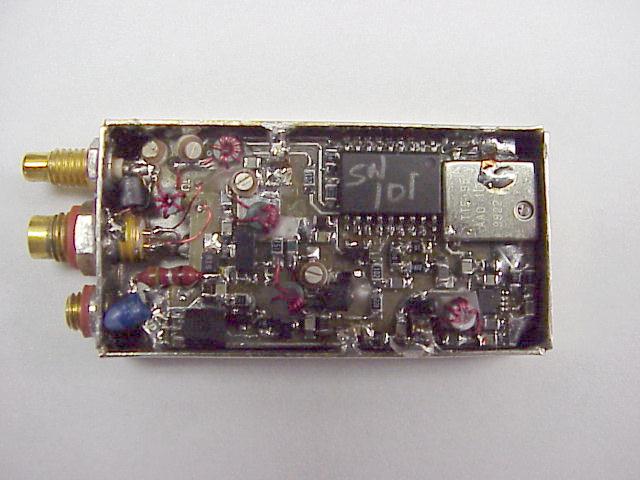
CST-703/V FCC ID# IP9CST703 S/N 101 One Channel Synthesized Transmitter Frequency Range 154 - 174 Mhz Power Output 500 mw I.C. and Transistor Discription: U1.................5.0 Volt regulator.......Toko TK11435CT-ND U2.................10Mhz 2.5ppm Reference...Temex TTF95AA010MHZ U3.................PLL......................Nat.Semi. 1501A U4.................Micrcontroller...........Microchip 16F84/10 U5.................Oscillator...............Maxim 2620 Q1.................FET......................Silconix 2N7000 Q2.................PNP......................Mot. 2N2907 Q3.................RF NPN......................Mot. BFR92A Q4.................RF NPN......................Mot. BFQ17 Q7,Q8,Q9,Q10.......AUDIO NPN...................Mot. 2N5088 RF Circuit Discription: The Microcontroller (U4) has 1 factory programmed frequency from 154 - 174 Mhz. The clock frequency of the microcontroller is 10 Mhz. The microcontroller sends data to the Phase Lock (U3), which converts the data into a dc voltage. This voltage is applied to the varactor which moves the oscillator (U5) frequency to programmed frequency. The oscillator output is fedback to the PLL (U2) and the RF pre-amp (Q3). When the oscillator is at the desired frequency the PLL lock detect output turns ON the N-Channel FET (Q1) which turns on the PNP transistor (Q2) and applies voltage to the pre-amp and the final amp (Q4). The harmonic output of (Q4) is attenuated by the low pass filter. Audio Circuit Description: The microphone signal is amplified by (Q9 and Q10). The pre- emphasis is handled by the RC combinations of both audio amplifiers. The low pass filter (Q7) attenuates the audio frequencies after 2700 Hz. THhe audio from the low pass filter is converted to a dc voltage, this voltage turns ON the AGC transistor (Q8) which shorts the audio from the microphone to ground to prevent over deviation. The varable resistor controls the amount of deviation to the varactor. Antenna Description: The antenna is a 15" center conductor from RG-174 coax cable, which is matched to the transmitters output with a matching network. Computer interface Description: The microcontroller has a 2 wire interface with the computer. When the program cable is connected to the transismitter and the computer this disables the transmitter and puts the microcontroller in program mode. The data from the computer is converted in a hex number and stored in EE of the microcontroller.
Schematics
.001 C2 9 .1UF C5 .IUF C1 4 352 Q2 VR1 5V C3 6 3.3UF .047 C6 5 100K R9 C3 0 470 100K R8 R1 5 3.3K 100K R2 1 Q4 702 C3 4 .22UF R6 1 33K C7 3.3UF R3 1K C1 7 .1UF C2 .01 C6 .1UF R2 4.7K C3 .001 C4 .001 C2 3 .001 R1 8 560 L1 FB R1 7 8.2K C3 1 3.3UF ,001 C3 5 470 C1 5 4.7 C1 5 20 C1 0 20 C1 0 20 C1 1 L1L2L8 20 C3 1 470 C2 5 300 R1 2 18 R1 3 300 R1 4 47 C2 6 Q5 7X D1 A7 R1 6 1K FB L5 VAL R? 3.3UF C3 0 .001 C1 8 L2 100 C2 2 10 C2 1 22 C2 0 R1 9 150NH L9 M4 E V1 M4 E V2 1PF C2 7 12 C2 4 R6 10 R7 100K QS Q6 8.2 C3 3 VAL L7 R2 0 82 L8 33K R6 2 C8 .47UF 6.8UF C9 R1 470 R5 3.3K C1 2 .47UF C2 8 470 C3 2 .001 R4 56 R1 100K +5V U3 2620 U1 8 5 X1 U2 (SH- 2) POWER SERIAL IN PGM +BAT CONN +BAT ANT CST 703- ( ) TX SECTION 3 11 6 +5V 16F84 SCR/ CLR 2 1 5 14 4 10MHZ 17 LE DATA CLK 11 10 9 LMX1501A 1 3 7 6 5 8 4 16 147 6 2 3 AUDIO (SH 2) 21703- TX +5V 1 4 2 GN D 3 ABCD 4 3 2 1 DCBA 1 2 3 4 A3 RevNum ber Ti t l e Size Da t e Filenam e Dr a wn b y ofSheet
Schematics
15OK R2 3 22K R2 4 A7 D3 3.3UF C3 9 100K R2 8 3.3UF C3 8 2.4K R2 6 2.4K R3 0 C4 4 .047 MMBT5088 Q9 R3 1 100K R3 8 2K C4 3 3.3UF 2.4K R3 7 R2 7 100K C4 7 .047 R3 5 100K R3 4 100K MMBT5088 Q1 0 R3 6 2K C4 6 1.UF R3 3 2.4K MMBT5088 Q8 C4 5 .047 R3 2 2.7K R2 9 2.7K MMBT5088 Q7 R2 5 150 C4 0 .0047 C4 1 .047 C4 2 3.3UF R2 2 10K 3.3UF C3 7 CST 703- AUDIO (SH 2) A 22 MIC AUDIO (SH 1) +3.5 (SH 1) 703- AUD ABCD 4 3 2 1 DCBA 1 2 3 4 A3 RevNum ber Ti t l e Size Da t e Filenam e Dr a wn b y ofSheet
Schematics
U1 + - 33K R1 1 .01 C7 1500 R1 3 R7 1MEG 100K R2 68K R1 1UF C2 1500 R6 100 C6 .1UF C4 C5 .1 100K R8 220K R9 C8 120 10K R1 0 .1UF C1 0 330K R3 C9 22 GN D 22 C1 1 10.24 X1 1MEG R1 2 R5 2.4K 1UF C3 R4 2.4K +5 +5 MICA1 3 8 7 3 5 6 15 CLR AUDIO 14 16 12 U2 MX128 A 22 CST 703- SCRAMBLER 703- SCR +5 ABCD 4 3 2 1 DCBA 1 2 3 4 A3 RevNum ber Ti t l e Size Da t e Filenam e Dr a wn b y ofSheet
Test Report
September 28, 2000 The audio frequency response, low pass filter test, occupied bandwidth, and frequency stability in this application for Type Certification for the CST-703 (FCC ID: IP9CST703) have been performed under my direct supervision. To the best of my knowledge these tests were conducted in accordance with the procedures outlined in Part 2 and Part 90 of the Commissions Rules and Regulations. I am presently employed by Tactical Technologies Inc. in Folsom, Pennsylvania as a Design Engineer. My prior experience consists of 10 years of designing and testing communication products in the VHF portions of the spectrum. Jeffrey N. Olsen Tactical Technologies Inc. Design Engineer
Test Report
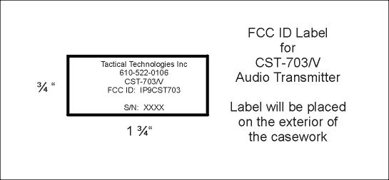
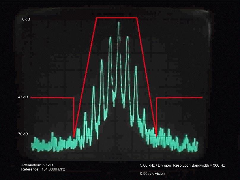
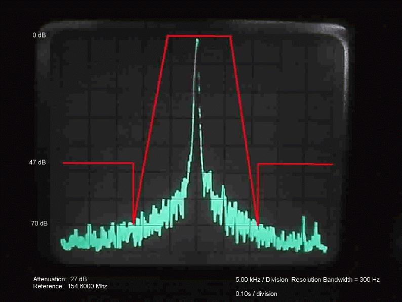
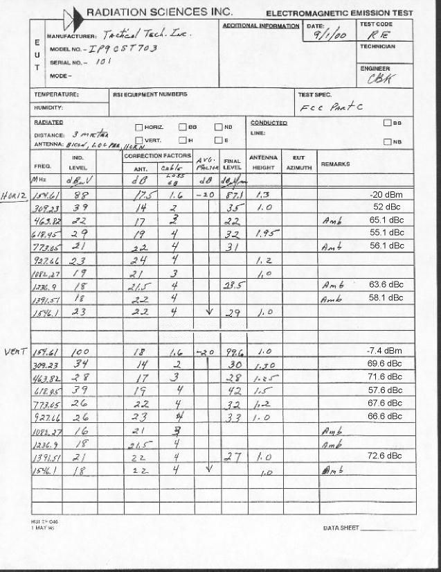
A. INTRODUCTION The following data are submitted in connection with this Application for Type Certifacation in accordance with Part 2, Subpart J, and Part 90, Subparts B,D, and I of the FCC Rules and Regulations. B. INFORMATION REQUIRED BY PART 2 - Paragragh 2.981 This section provides data as required by the following Paragraghs: 2.983,2.985,2.987,2.989,2.993,2.995,2.997,2.999 and 2.1003. 2.983 (a) See Form 731 2.983 (b) See Form 731 2.983 (c) Quanity production is anticipated 2.983(d)(1) - (d)(3) See Form 731 2.983)d)(4) The maximum transmitter power output is .50 Watt. (5) RF final amplifier: At 9.00 Vdc and .09 Adc, Po = .50W. (6) The function of each active device is included in the exhibits section of this application. (7) Complete circuit diagrams are included. (8) Operating instructions are included in the exhibits section of this application. (9) Complete tune-up procedures are included in the exhibits section of this application. (10) A discription of all circuitry and devices provided for determining and stabilizing frequency is included in the exhibits section of this application. (11) A description of any circuits and devices employed for suppression of spurious radiation, for limiting modulation, and for limiting power in the exhibits section of this application. (12) N/A 2.983(e) The data required by Paragraghs 2.985 through 2.987, inclusive, measured in accordance with the procedures contained in Paragragh 2.999, are included in Section E of this application. (f) A photogragh or drawing of the equipment identification plate or label showing the information to be placed thereon is included in the exhibits section of this application. (g) The required 8 x 10 photograghs revealing equipment construction and layout are included in the exhibits section of this application. (h) N/A (i) N/A 2.997 The frequency spectrum investigation for spurious emissions per Paragraghs 2.991 and 2.993 include from the lowest frequency within the transmitter to at least the 10th harmonic of the carrier frequency. 2.999 The measurement procedures employed are in accordance with the requirements set forth in Paragragh 2.947. 2.1003 The identification label complies with the requirements of this Paragragh and Paragragh 2.925. C. SUBMISSION OF EQUIPMENT FOR TESTING - Paragragh 2.943 Upon request, the test sample will promply be made available by Radiation Science Inc. D. DESCRIPTION OF MEASUREMENT FACILITIES - Paragragh 2.947 The open-field tests were performed on the 3 meter range maintained by Radiation Science Inc. Complete desciption and measurement data have been placed on file with the Commission. E. TEST DATA This section contains results of measurements required by Parts 2 and 90 of the rules. Data are presented in tabular and/ or graghical form, and measurement procedures are described within the text of each reported test. The test sample operated on 154.6125 Mhz. 1. RF POWER OUTPUT - Paragraghs [2.985,2.983(d)(5),90.205(b)] Measurements pertaining to the power output of the transmitter were performed by the manufacturer. To the best of my knowledge, these tests were conducted in accordance with the procedures outlined in Parts 2 and 90 of the Commissions Rules and regulations. The data presented on Table 1 demonstrates complience with the appropriate technical standards. 2. MODULATION CHARACTERISTICS - Paragragh [2.987(a), 90.211] Measurements pertaining to the modulation characteristics were performed by the manufacture. To the best of my knowledge, these tests were conducted in accordance with the procedures outlined in Parts 2 and 90 of the Commisions Rules and regulations. The data presented on figures 1 and 2 demonstrates complience with the appropriate technical standards. 3. OCCUPIED BANDWIDTH - Paragraghs [2.989(c)(1), 90.209(c)] Figures 3 and 4 contain pictures taken from a Hewlett Packard 8558B Spectrum Analyzer. The transmitter was modulated with a sine wave tone at 2500 Hz at a level 16 db above the required to produce 50% modulation at the frequency maximum responce. Paragragh 90.209(c) requires that the mean power of emissions shall be attenuated below the mean output power of the transmitter by the following amounts. (a) On any frequency removed from the assigned frequency by more than 50% but not more than 100% of the authorized bandwidth (at least 25db) (b) On any frequency removed from the assigned frequency by more than 100% but not more that 250% of the authorized bandwidth (at least 35db). (c) On any frequency removed from the assigned frequency by more than 250% of the authorized bandwidth [at least 50 + log(w) db or 80 db, whichever is the lesser attenuation]. 4. SPURIOUS EMISSIONS AT THE 50 OHM TEST POINT ON THE TRANSMITTER [2.991, 90.209(c)] The transmitter was modulated per paragragh 2.989(c)(1). The spectrum was checked with the spectrum analyzer from 10 Mhz to the 10th harmonic of the carrier frequency. Observed emissions not reported are attenuated more than 20 db below the permissible value of 47 db, i,e., 50 + log (.5W) = 47 db given by Section 90.209(c)(3). The data in Table 1 verifies that the test sample complies with Paragragh 90.209(c)(3). TABLE 1 CONDUCTED SPURIOUS EMISSIONS DATA EMISSION EMISSION FCC FREQUENCY LEVEL LIMIT (Mhz) (dbc) (dbc) 154.6 REFEERENCE +27 Dbm 47 309.2 -54 47 463.8 -62 47 618.4 -75 47 773.0 >-75 47 927.6 >-75 47 1082.2 >-75 47 1236.8 >-75 47 1391.4 >-75 47 1546.0 >-75 47 5. FIELD STRENGTH OF SPURIOUS RADIATION - Paragraghs [2.993,2.997,90.209(c)(3)] Measurememnts were made on the three meter range maintained by Radiation Science Inc. to quantify spurious emission level that] are radiated directly from the cabinet, control circuits, power leads and intermediate circuit elements under normal conditions of installation and operation. Particular attenuation was paid to harmonics of the carrier frequency as well as those frequencies removed from the carrier by multiples of the oscillator frequency. Data is submitted in Table 2 showing …
Text truncated - open the document above for the full version.
Test Report
CST-703/V Emmission Designator 11K2F3E FCC ID# IP9CST703 Modulation Limiting Curve (Sec. 2.1047b) and Maximum Frequency Deviation Input Signal Level VS Deviation NBFM 100% = 2.5 KHZ 0.0% 20.0%40.0%60.0%80.0% 100.0%120.0% 100Hz 300Hz 500Hz 750Hz 1000Hz 1500Hz 2000Hz 2500Hz 3000Hz 4000Hz 5000Hz FREQUENCY DEVIATION - 60 Dbm - 50 Dbm - 40 Dbm - 30 Dbm
Test Report
FCC ID# IP9CST703 Emissions Designator: The necessary bandwidth calculation under part 2.201 for the IP9CST703 transmitter falls under the FM formula: D = 2.5 kHz M = 3 kHz K = 1 BW = 2M + 2DK Estimated BW = 11kHz The emissions designator based on measurement is 11K2F3E. This emissions designator indicates that this is a NBFM audio channel transmitter with an occupied bandwidth of 11.2 kHz.
Test Report
FCC ID IP9CST703 RF Output Measurement The RF Power output measurement was made with an unmodulated carrier at the RF connector of the transmitter. The power was measured with a HP 432A Watt Meter. The RF load was 50 ohms 0j ohms. The power was measured through out the operating frequencies in 2.5 Mhz steps at 9 volts and 7.65 volts. Frequency(Mhz) Pout(mw) @9 volts 154.000 420 156.500 425 159.000 425 161.500 430 164.000 430 166.500 430 169.000 440 171.500 440 174.000 430 Frequency(Mhz) Pout(mw) @7.65 volts 154.000 290 156.500 290 159.000 290 161.500 300 164.000 300 166.500 300 169.000 300 171.500 295 174.000 290
Test Report
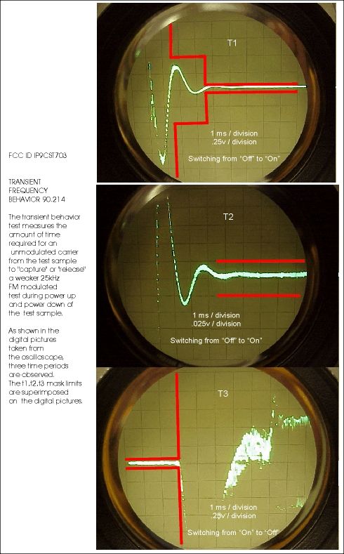
BLOCK DIAGRAM Transient Freque ncy Behavior 90.214 50 Ohm Termina tio n UnitAttenuatorDirectionalAttenuatorCombinerModulated UnderCouplerSignal Tes tGe nera tor Tes t Receiver RF De tecto rTriggerOscillos cope The unit under test (IP9CST703) was connected to a Directional Coupler. The two outputs from the coupler were connected to a RF Detector Diode and the other output from the coupler was combined with a 25kHz FM modulated test signal. The output from the combiner was connected to a test receiver, the demodulated audio from the receiver was connected to the oscilloscope input and the external trigger input on the oscilloscope was connected to the output of the RF diode detector. Power was applied to the test unit from a power supply, and the unit was turned OFF/ON manually with a test lead applied to the positive terminal of the power supply. When power was applied to the unit under test, the microprocessor sends the frequency data to the PLL. The PLL outputs a voltage to the VCO to tune the oscillator to the programmed frequency, after the frequency is locked the output from the PLL (lock detect) turns on the power to the pre-driver and the final amplifier. Three time periods were captured on the storage oscilloscope and recorded. The three pictures show the turn on and turn off points and the related frequency displacement. The t1,t2, and t3 mask limits are superimposed on each of the data runs.
Contact Information
Applicant
Richard B Snyder(President)
Test Firm
Radiation Sciences IncorporatedDaniel Signore
215-256-4133Fax: 215-256-0775
Technical Specifications
| # | Rule Parts | Frequency Range | Power Output | Emission | Tolerance |
|---|---|---|---|---|---|
| 1 | 90 | 150 MHz - 174 MHz | 440.00 mW | 11K0F3E | 2.5000000000 ppm |
Other Applications from Tactical Technologies Inc
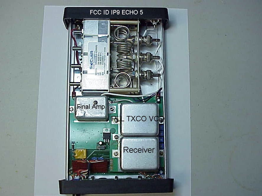
IP9ECHO5
Aug 21, 2005Repeater
Equipment Class
TNB - Licensed Non-Broadcast Station Transmitter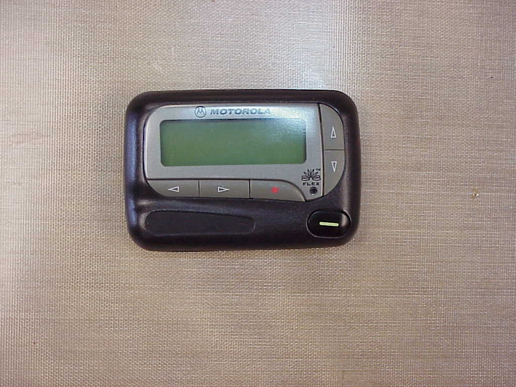
IP9801VI
Jun 22, 2005Synthesized VHF Surveillance Voice Transmitter
Equipment Class
TNT - Licensed Non-Broadcast Transmitter Worn on Body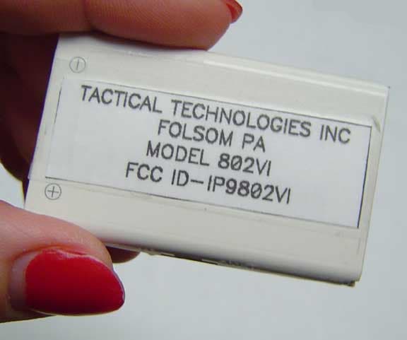
IP9802VI
May 05, 2005Synthesized VHF Surveillance Voice Transmitter
Equipment Class
TNT - Licensed Non-Broadcast Transmitter Worn on Body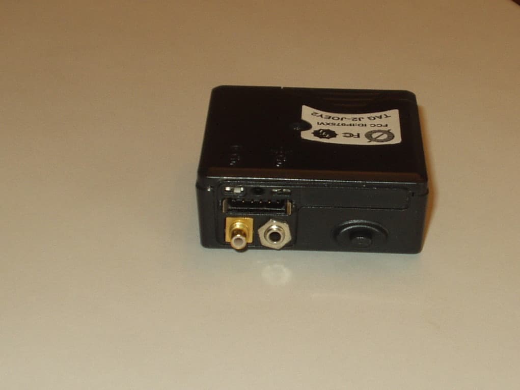
IP975XVI
Mar 28, 2005Synthesized VHF Surveillance Voice Transmitter
Equipment Class
TNT - Licensed Non-Broadcast Transmitter Worn on Body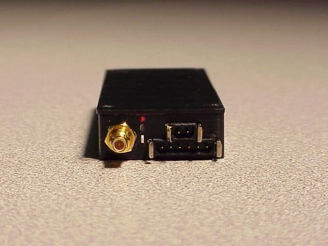
IP9751V
Dec 01, 2002Law Enforcement Surveillance Transmitter
Equipment Class
LMS - Part 90 Location & Monitoring Transmitter