IP9RX400Personal Protection Belt Worn Receiver
Tactical Technologies Inc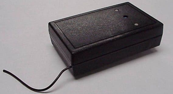
Click to zoom
Application Details
- Equipment Class
- CYY - Communications Receiver used w/Pt 15 Transmitter
- Date of Grant
- Sep 11, 2000
- Application Purpose
- Original Equipment
- Date of Application
- Aug 17, 2000
- Equipment Note
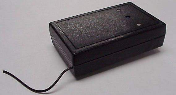
- Personal Protection Belt Worn Receiver
- Frequency Range
- 418.00000000 - 418.00000000
- Company
- Tactical Technologies Inc
- Country
- United States
Documents & Files

Document Text
Text extracted from the exhibit documents filed with the FCC. Open a document above to read the original.
Users Manual
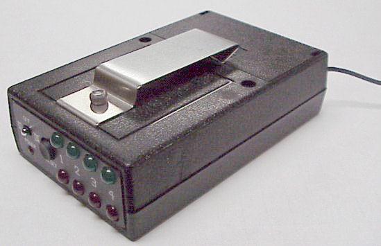
MINDA PERSONAL PROTECTION SYSTEM RX-400 MINDA Portable Receiver Operating Instruction Rev 1.0 June 2000 Tactical Technologies Inc. 1701 Second Ave Folsom, PA 19033 610-522-0106 www.tacticaltechnologies.com RECEIVER RX-400 - Quick guide Each 'MINDA' TX-400 receiver can display two status indications from up to four different transmitter units, coded 1-4 and all operating with the same group code. Pressing the RED button on a 'key-fob' style transmitter should light the Red LED on the receiver, whilst the BLACK one lights the Green LED. 'BEEP' mode is selected by moving t he On/Off switch in the direction away from the eight LED's, and 'SILENT' mode is selected by moving the On/Off switch towards the eight LED's. Briefly pressing the 'Reset' button will cancel any audible alert, initiate a 'lamp-test' and extinguish any LED's that may have been illuminated prior to resetting. Additional alerts provided 1. A Transmitter Low-Battery alert causes the appropriate LED indicator on the receiver to 'blink' out briefly about once per second. 2. A Receiver jamming alert will cause a series of audible 'beeps' to be generated. If this occurs you should move to an interference-free location and as soon as the interference clears the 'beeps' will cease. TRANSM ISSION RANGE. When using the 'MINDA' system over a line-of-sight path you are likely to obtain a working distance in excess of 100 yards, whereas in a busy street, hotel or station the range will be noticeably less. It is recommended that, before using a 'MINDA' system in a 'live' operational situation, you carry out a few tests in the location(s) of interest to confirm consistent and reliable operation. 'MINDA' SYSTEM - FULL USER'S GUIDE GENERAL. A system, comprising transmitter(s) and receiver, will have been supplied programmed with a specific 'Group Identity' out of the 255 possible codes available. This is set during production to '94' (hex.) unless an alternative group code identity has been requested by a particular customer. Individual transmitters will also have been programmed with a Unit Identity (1,2,3 or 4), which will be show n on t he label on t he back of the case. The micro-processor controlled receiver will only respond to signals from those transmitters sending the same 'group-code' identity that it has been pre-programmed to accept. This capability minimizes the risk of interference between similar systems that happen to be operating within radio range of one another. 'MINDA' transmitter and receiver units can be reprogrammed to different codes if required, but this operation requires the use of workshop facilities including a PC, software and a special interface unit. Contact your supplier for more details. THE 'MINDA' RECEIVER RX-400. Each 'MINDA' receiver can display two status indications from up to four different transmitter units, coded 1-4 and all operating with the same group code. Pressing the RED button on a 'key- fob' style transmitter should light the Red LED on the receiver, whilst the BLACK one lights the Green LED. Operation The receiver is very easy to use, and has two modes of operation, 'SILENT' and 'BEEP'. If the 'BEEP' mode is selected by moving t he On/Off switch in the direction away from the eight LED's, when a 'wanted' signal is received the appropriate status LED will light and an audible pulsed tone alarm will be heard. The tempo of this pulsed tone is faster for a 'Red' alarm than for a 'Green' alarm, thereby facilitating the aural identification of 'Urgent' and 'Non-Urgent' transmissions. When 'SILENT' mode is selected by moving the On/Off switch towards the eight LED's, the appropriate LED will still light but all audible tone signals are inhibited. Silent signaling will be provided by means of a built-in vibrator. Whenever the receiver is initially switched on, all of the eight large LED's will be briefly illuminated, in pairs, to provide a 'lamp-test' and give visual confirmation that the microprocessor is operating correctly. The small red LED adjacent to the On/Off switch will then flash regularly as long as the receiver is operating but not receiving any signals. As soon as the receiver detects a signal the red LED will light continuously. BE AWARE that any signal received will cause this to happen, whether it is local electrical interference, a transmission with a different group code, or a 'wanted' signal from a transmitter on your own group code. Briefly pressing the 'Reset' button will cancel any audible alert, initiate a 'lamp-test' (see above) and extinguish any LED's that may have been illuminated prior to resetting. Additional alerts provided 1. Transmitter Low-Battery alert. A valid transmission received from a transmitter with a weak, but not completely flat, battery will cause the appropriate LED indicator on the receiver to 'blink' out briefly about once per second. This will indicate to the operator that that particular transmitter should have its battery replaced at the earliest opportunity. 2. Receiver jamming alert Any signal received on the frequency will cause the receiver to lock-on, whether it is local electrical interference, a transmission with a different group code, or a 'wanted' signal from a transmitter on your own group code. However, if the 'MINDA' receiver is 'jammed' by a continuous unrecognized signal, then after a short period of time (set during manufacture to 5 seconds, but re-programmable) it produces a series of audible 'beeps' to alert the user and enable him to move to an interference-free location. As soon as the interference clears the 'beeps' will cease. More about the Battery Economizer The battery economizer operates by switching the receiver on for a very brief period, looking for a signal, and if nothing is found switching it off again. If a signal is found, the receiver 'locks-on' for long enough to process and display any alarm signal that may have been received. The small red LED adjacent to the On/Off switch displays the status of the battery ec…
Text truncated - open the document above for the full version.
Operational Description
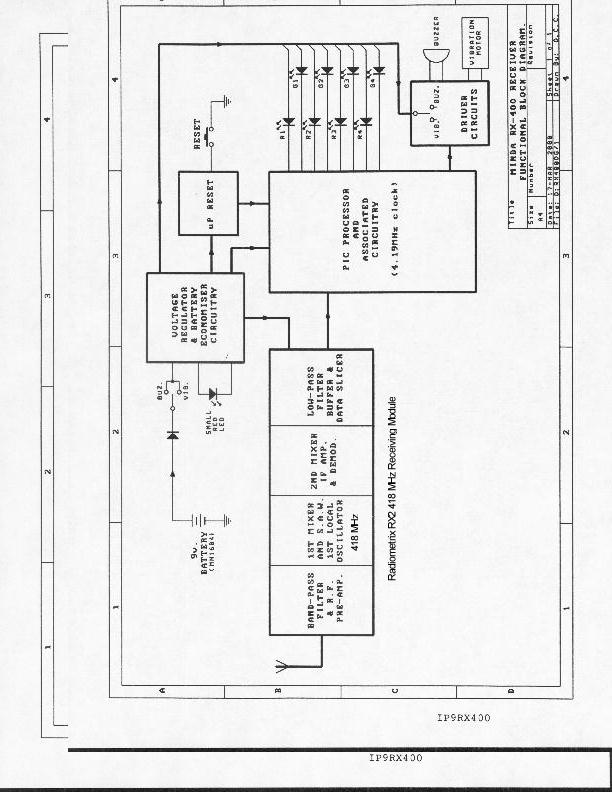
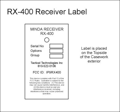
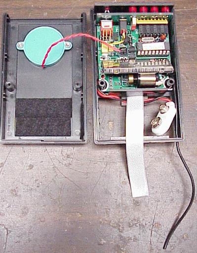
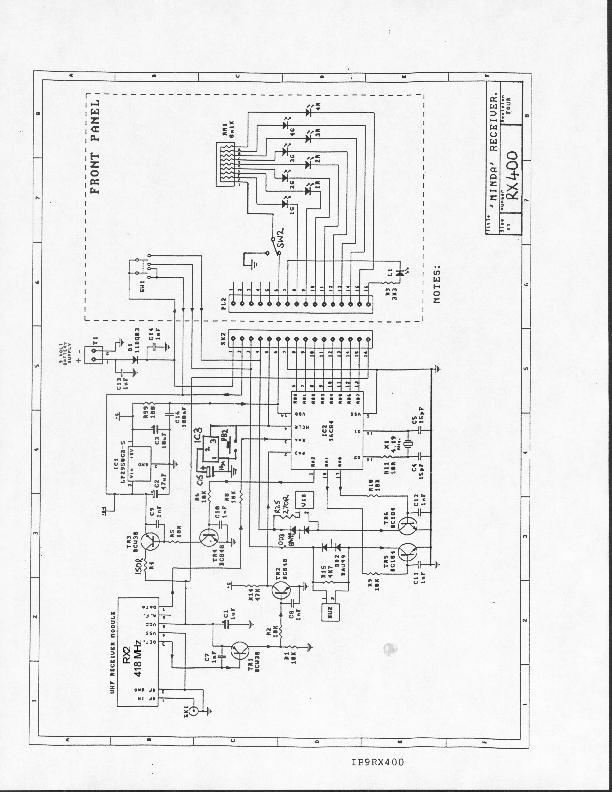
RX-400 CIRCUIT DESCRIPTION IP9RX400 The RX-400 Intelligent Receiver is built around a pair of interconnecting PCB's. The main board contains a Radiometrix RX2 418 MHz receiver module, a PIC 16F84-04P microprocessor with a 4.19 MHz crystal and other associated peripheral components. It also contains a 5-volt regulator, a vibration motor, a 2-way on-off-on power switch, a momentary-action 'reset' push button, and other discrete components. The smaller 'front-panel' PC board contains four pairs of red and green LED's and a smaller red LED. A ceramic 'buzzer' is attached to the case and connected to the main PCB by a short lead. A 9-volt MN1604 battery provides power. A user can decide whether, on receipt of a valid signal, the receiver should produce an audible alert or vibrate (almost) silently, by switching the on-off-on power switch in the appropriate direction. The MINDA 'family code' is pre-programmed into the EEPROM of the microprocessor along with other user-selectable operating parameters by connecting the lead from programming kit (connected to an IBM compatible PC) to the 8-wya socket on the PCB. The numerous programmable options available are fully described in the user's operating manual. The microprocessor controls the operation of a battery-economizer circuit which powers the receiver module for a brief period at regular intervals until such time as a valid signal is detected after which power is applied continuously until that signal disappears. The small red LED on the front panel lights whenever the receiver is powered, thereby giving the user an indication of activity on 418 MHz. When a valid signal is received (one bearing the same family code as the RX-400 microprocessor has been pro-programmed to expect) the PIC decodes the serial data from the RX2 module and displays the results by lighting one of the four pairs of LED's on the front panel and sounding the 'buzzer' or activating the vibration motor. The display will show the unit identity (1,2,3,or 4) and status (red to green) of the originating transmitter and the condition of its battery (OK or LOW). Low transmitter battery voltage is displayed by causing the appropriate lit LED to blink out briefly at regular intervals. Once an incoming signal has been received, decoded and acted upon, the user can extinguish and LED remaining alight by pressing and releasing the 'reset' button on the front panel of the receiver.
Contact Information
Applicant
Richard B Snyder(President)
Test Firm
Radiation Sciences IncorporatedDaniel Signore
215-256-4133Fax: 215-256-0775
Technical Specifications
| # | Rule Parts | Frequency Range | Power Output |
|---|---|---|---|
| 1 | 15B | 418 MHz - 418 MHz | - |
Other Applications from Tactical Technologies Inc
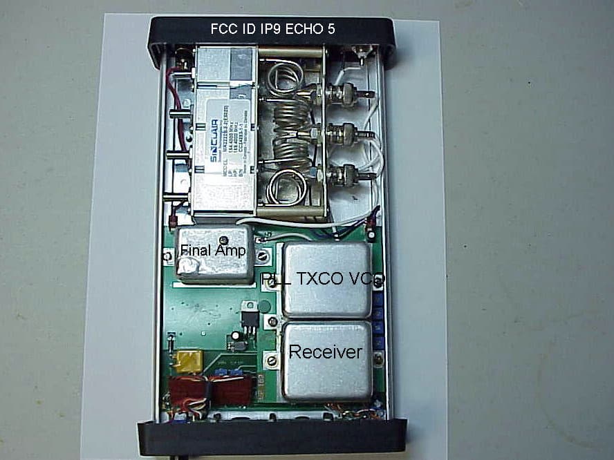
IP9ECHO5
Aug 21, 2005Repeater
Equipment Class
TNB - Licensed Non-Broadcast Station Transmitter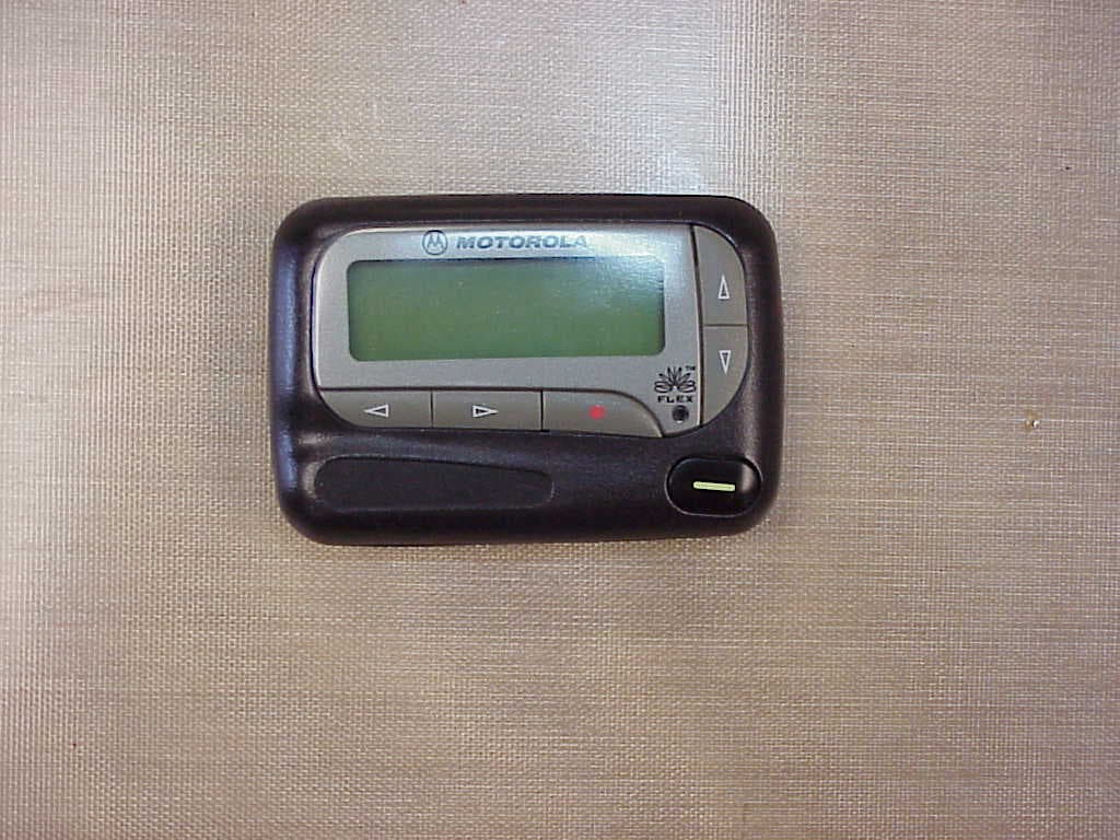
IP9801VI
Jun 22, 2005Synthesized VHF Surveillance Voice Transmitter
Equipment Class
TNT - Licensed Non-Broadcast Transmitter Worn on Body
IP9802VI
May 05, 2005Synthesized VHF Surveillance Voice Transmitter
Equipment Class
TNT - Licensed Non-Broadcast Transmitter Worn on Body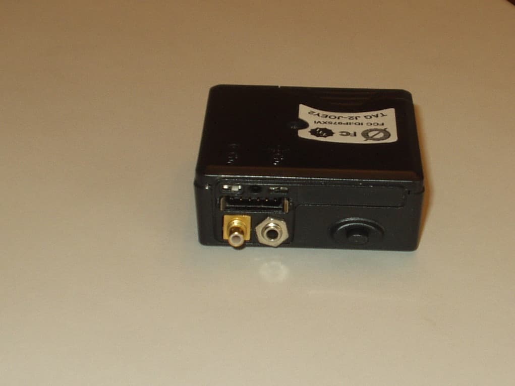
IP975XVI
Mar 28, 2005Synthesized VHF Surveillance Voice Transmitter
Equipment Class
TNT - Licensed Non-Broadcast Transmitter Worn on Body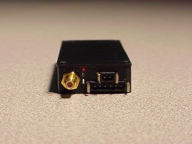
IP9751V
Dec 01, 2002Law Enforcement Surveillance Transmitter
Equipment Class
LMS - Part 90 Location & Monitoring Transmitter