IP9RX500Personal Protection Desktop/Mobile Receiver
Tactical Technologies Inc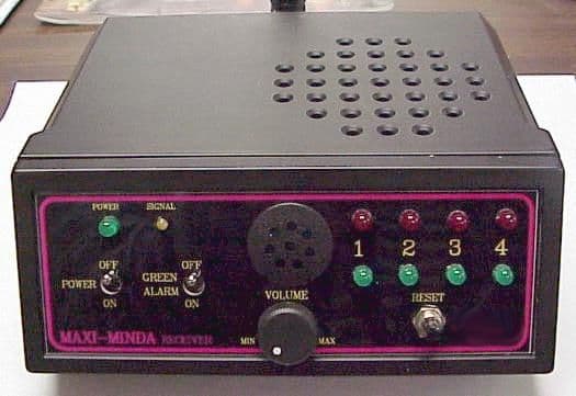
Click to zoom
Application Details
- Equipment Class
- CYY - Communications Receiver used w/Pt 15 Transmitter
- Date of Grant
- Sep 12, 2000
- Application Purpose
- Original Equipment
- Date of Application
- Aug 17, 2000
- Equipment Note
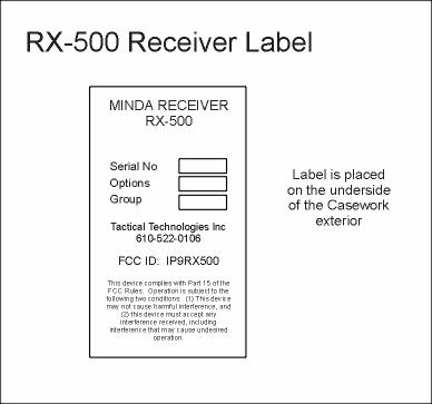
- Personal Protection Desktop/Mobile Receiver
- Frequency Range
- 418.00000000 - 418.00000000
- Company
- Tactical Technologies Inc
- Country
- United States
Documents & Files
Document Text
Text extracted from the exhibit documents filed with the FCC. Open a document above to read the original.
Users Manual
MINDA PERSONAL PROTECTION SYSTEM RX-500 Maxi-MINDA Receiver Operating Instruction Rev 1.0 June 2000 Tactical Technologies Inc. 1701 Second Ave Folsom, PA 19033 610-522-0106 www.tacticaltechnologies.com IMPORTANT NOTE You are advised to read these instructions carefully and completely before using this equipment BUT , if you really cannot wait, the Quick-Start Guide found at the end of this manual will give you the basic do’s and don’ts... OVERVIEW Thank you for purchasing a ‘Maxi-MINDA’ RX-500 receiver which uses a low-power microprocessor to offer the following options: • A very secure Family Identity Code • Very low stand-by power consumption by using battery economizer. • Automatic battery back-up operation if external power source fails. • Fully protected against inadvertent reversal of external D.C. supply. • Programmable alarm signal - can repeat at regular intervals. • Optional loud alarm (up to 1.5 watts) when using external power. • Internal loudspeaker and jack socket for connection of an external alarm loudspeaker. • Relay-switched contacts or open-drain FET output for external switching. • 9 volt 200mA regulated D.C. output is available to power other equipment (only when receiver is using external power). • Jamming alert - with programmable time delay. • Lost signal alert - with programmable time delay and repeat option. • Battery monitoring of transmitters that are using the same Family Code. • Serial programming interface to a PC (additional items required) CAUTION A ‘Maxi-MINDA’ receiver will only respond to signals from those transmitters sending the same Family Identity Code as the one that it has been pre-programmed to accept. This minimizes the risk of interference between similar systems that happen to be operating within radio range of one another. It is absolutely vital therefore, to ensure that all transmitter and receiver units that have to operate together are programmed correctly with the same Family Identity Code. Any signals received from an ‘alien’ transmitter operating within range will not be decoded and, instead, treated by the receiver as radio interference on the channel. BATTERY INSTALLATION The ‘Maxi-MINDA’ receiver requires a 9-volt MN1604 alkaline battery which is fitted into the removable cassette accessible from the rear panel. This battery supply is automatically disconnected whenever external power of adequate voltage and correct polarity is applied through the rear connector. BATTERY ECONOMIZER The battery economizer operates by switching the receiver on for a very brief period, looking for a signal and if nothing is found, switching it off again. If a signal is found to be present, the receiver then ‘locks-on’ for long enough to process and display any alarm signal that may have been received. If the single green LED above the ‘On/Off’ switch regularly flashes, this indicates that the battery economizer circuit is in operation - if it illuminates steadily then the economizer has been over- ridden. While the receiver is in the pulsing ‘standby’ mode, it is in fact, switched on for less than two percent of the time, thereby dramatically extending the RX-500's operating endurance when using the internal battery supply. The slight penalty for using the battery economizer is that any incoming alarm transmission must last long enough to catch the receiver during one of its ‘on’ periods and ensure that it is recognized and decoded. All intelligent TX-500 Keyfob or TX-600 Belt transmitters will automatically transmit a signal long enough for this to occur. Possible problems when using a MINDA TX-400 transmitter can be eliminated by ensuring the transmit button on the keyfob is always pressed for at least one second. As supplied, unless a customer has requested otherwise, an RX-500 ‘Maxi-MINDA’ receiver normally has its battery economizer enabled while it is operating on its own internal battery and disabled (i.e. receiver runs continuously) once external supplies are present. This arrangement can be changed at the factory, if required, by re-programming the receiver. EXTERNAL POWER SOURCES If an external power source of greater than 10 volts, and of correct polarity, is connected to the Maxi-MINDA’ RX-500, the receiver will automatically use this supply in preference to its internal battery. If for any reason the external supply fails (possible due to AC supply failure) the unit then reverts to its internal battery and continues operating normally. TX UNIT IDENTITIES A ‘Maxi-MINDA’ receiver can be configured (by re-programming) to respond in different ways and with different timings to each of the four possible transmitter Unit Identities (1, 2, 3 or 4), to suit particular operational needs ‘RED’ AND ‘GREEN’ ALERTS When the ‘Maxi-MINDA’ receiver is operating and a valid signal is received from a transmitter with the same Family Identity Code, the appropriate red or green LED on the receiver will light and an audible pulsed tone alarm will be heard. The tempo of this pulsed tone is faster for a ‘Red’ alarm than for a ‘Green’ alarm, thereby facilitating t he aural discrimination between urgent and non- urgent transmissions. When the ‘Maxi-MINDA’ is using its internal battery the alarm tone is produced by a piezo beeper. When an external power supply is being used an additional high power amplifier driving an internal loudspeaker is automatically enabled. The loudness of the alarm signals produced by the piezo beeper cannot be adjusted. If desired, the beeper can be switched off completely so that all audible alarms are produced only through the loudspeaker with their loudness (from silence to full-volume) being adjusted by means of the front panel volume control. To turn off the beeper refer to the paragraph entitled ‘Disabling the Piezo Alar m’, but note that this should only be done when the receiver is always to be powered from an external source. In some operational situations it may be desirable for the ‘Maxi-MINDA’ receiver to remain silent whenev…
Text truncated - open the document above for the full version.
Operational Description
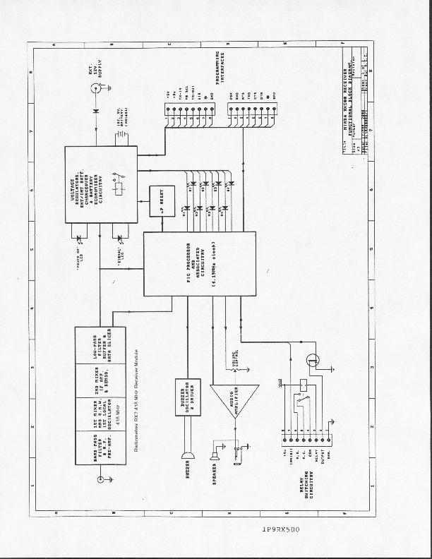
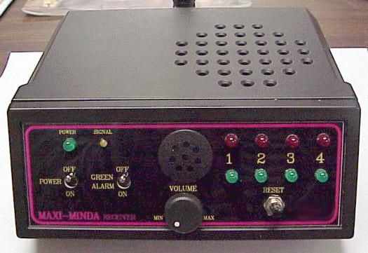
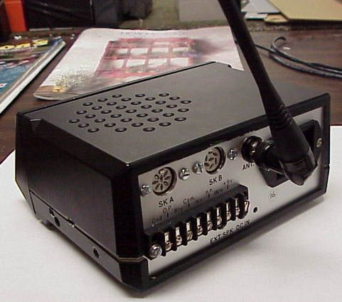
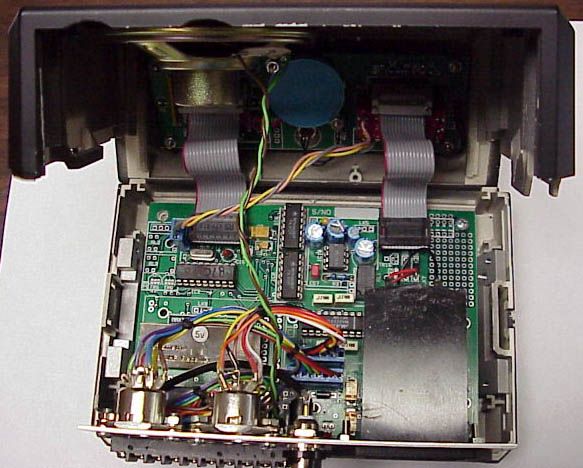
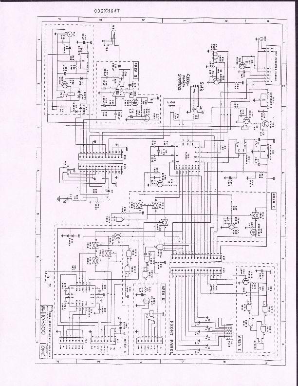
RX-500 CIRCUIT DESCRIPTION IP9RX500 The RX-500 Intelligent Desktop/Mobile Receiver is powered by an internal 9VDC 1604 battery or from an external DC supply of 10 to 16 volts, with automatic changeover back to the internal battery in the event of external supply failure. It comprises a main PC board connected by ribbon cables to a smaller PC board located behind the sloping front panel of the receiver and by cabling to connectors mounted on the metal rear panel. The main PC board contains a Radiometrix RX2 418 MHz receiver module, a PIC 16F84-04P microprocessor with a 4.19 MHz crystal and other associated peripheral components. Also included are two 5-volt regulators, an audio amplifier, relay switching circuitry, and a serial data interface. On the front panel is an On/Off power switch, a Green Alert On/Off switch, four pairs of Red and Green LED's, a green Power LED, a smaller yellow Signal LED, as well as a volume control, reset push button and a ceramic buzzer. An upward facing loudspeaker is fitted into the top of the case in order to produce a louder audible signal when the receiver is powered from an external supply. The appropriate MINDA 'family code' can be programmed into the EEPROM of the microprocessor along with other user-selectable operating parameters by connecting a suitable lead from an IBM compatible PC to the 8-way DIN socket on the rear of the receiver. The numerous programmable options available are fully described in the operator's manual. The receiver's microprocessor controls the operation of a battery economizer circuit which powers the receiver module for a brief period at regular intervals until such time as a valid signal is detected after which power is applied continuously until that signal disappears. The green LED on the front panel lights whenever power is applied to the receiver and the yellow LED lights on receipt of any signal above the pro- set carrier threshold, thereby giving the user an indication of activity on the radio channel being monitored. When a valid signal is received, the microprocessor decodes the serial data from the Radiometrix module and displays the result by lighting one of the four pairs of LED's on the front panel and sounding the 'buzzer' or producing a loud tone through the loudspeaker. The front panel display will show the unit identity and status of the originating transmitter and the condition of its battery. Low transmitter battery voltage is displayed by causing the appropriate lit LED to blink out briefly at regular intervals. Once an incoming signal has been received, decoded and acted upon, the user can extinguish any LED remaining alight by pressing and releasing the reset push button on the front panel of the receiver. A BNC connector on the rear panel of the unit allows a suitable antenna to be connected to the Radiometrix receiver module. The serial data interface built into the RX-500 enables all of the programmable functions to be read out or modified by the use of an IBM compatible PC running the MINDA programming software. Furthermore, by connecting a second lead from the RX-500 to any intelligent MINDA transmitter, the receiver's serial interface can also be used to program those transmitters, if required.
Contact Information
Applicant
Richard B Snyder(President)
Test Firm
Radiation Sciences IncorporatedDaniel Signore
215-256-4133Fax: 215-256-0775
Technical Specifications
| # | Rule Parts | Frequency Range | Power Output |
|---|---|---|---|
| 1 | 15B | 418 MHz - 418 MHz | - |
Other Applications from Tactical Technologies Inc
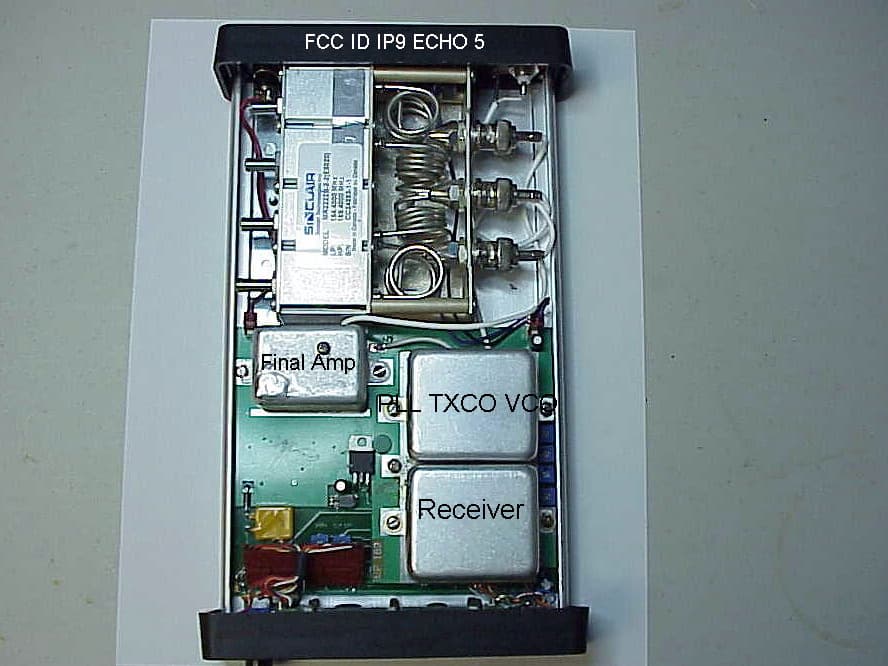
IP9ECHO5
Aug 21, 2005Repeater
Equipment Class
TNB - Licensed Non-Broadcast Station Transmitter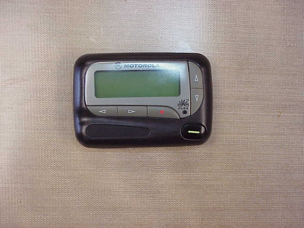
IP9801VI
Jun 22, 2005Synthesized VHF Surveillance Voice Transmitter
Equipment Class
TNT - Licensed Non-Broadcast Transmitter Worn on Body
IP9802VI
May 05, 2005Synthesized VHF Surveillance Voice Transmitter
Equipment Class
TNT - Licensed Non-Broadcast Transmitter Worn on Body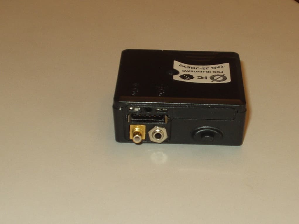
IP975XVI
Mar 28, 2005Synthesized VHF Surveillance Voice Transmitter
Equipment Class
TNT - Licensed Non-Broadcast Transmitter Worn on Body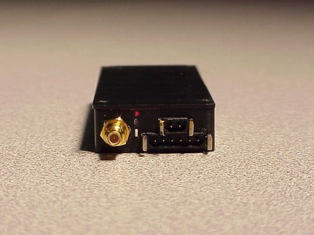
IP9751V
Dec 01, 2002Law Enforcement Surveillance Transmitter
Equipment Class
LMS - Part 90 Location & Monitoring Transmitter