IP9TX500
Tactical Technologies Inc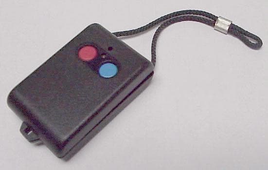
Click to zoom
Application Details
- Equipment Class
- DSC - Part 15 Security/Remote Control Transmitter
- Date of Grant
- Sep 14, 2000
- Application Purpose
- Original Equipment
- Date of Application
- Aug 17, 2000
- Frequency Range
- 418.00000000 - 418.00000000
- Company
- Tactical Technologies Inc
- Country
- United States
Documents & Files
Document Text
Text extracted from the exhibit documents filed with the FCC. Open a document above to read the original.
Users Manual
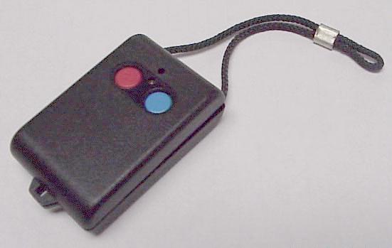
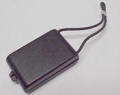
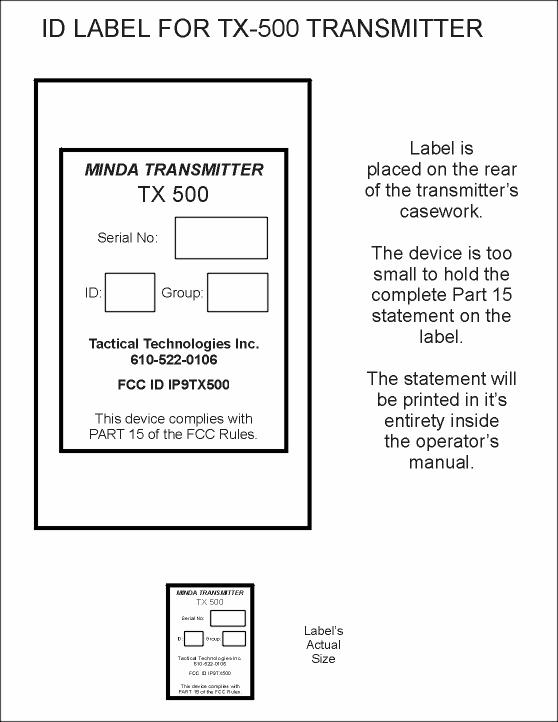
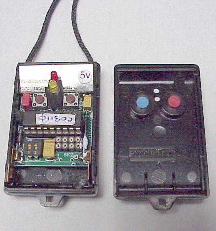
MINDA PERSONAL PROTECTION SYSTEM TX-500 INTELLIGENT KEY-FOB TRANSMITTER Operating Instruction Rev 1.3 June 2000 Tactical Technologies Inc. 1701 Second Ave Folsom, PA 19033 610-522-0106 www.tacticaltechnologies.com OVERVIEW Thank you for purchasing a MINDA Intelligent Transmitter, which uses a low-power microprocessor for ‘house-keeping’ and offers the following programmable options: • A Unit Identity Code (TX ID number 1,2,3,or 4) which will allow a single receiver to identify up to four different transmitters. • A very secure Family Identity Code, enabling secure use of multiple groups of transmitters and receivers together in the same location - without receiving alarms in ALL receivers. • Full compatibility with other MINDA equipment • Alarm signal repeat at programmable intervals • Automatic transmission of Confidence signals is possible • Transmitter ‘Low Battery’ alert sent to receiver • Very low power consumption Keep this instruction manual in a safe place - it contains important information and helpf ul tips which will assist you to obtain the best possible performance from your new MINDA system. OPERATING FREQUENCY All MINDA systems for use in the United States operate on a frequency of 418MHz in the UHF band. The operating radio frequency cannot be changed to suit a specific customer’s needs. BATTERY INSTALLATION The MINDA TX-500 transmitter requires an internal 12 volt 33mA/hour battery type GP 23A (Duracell type MN-21). To install a new battery into a key-fob style transmitter, the two-piece case must be pried open by inserting and carefully twisting a flat-bladed screwdriver into the groove formed by the two case halves. The old battery can then be removed and replaced by a new one, taking care to ensure that it is orientated in accordance with the polarity markings on the inside of the case. The case top should then be carefully aligned with the LED and gently but firmly snapped closed just using finger pressure. OPERATION The TX-500 will only communicate with an appropriate MINDA receiver, such as the RX-400 pocket receiver, or the RX-500 portable/mobile/tabletop receiver. The TX-500 is operational immediately upon inserting the battery. The unit is equipped with an On/Off switch that is magnetically controlled. To turn the TX-500 OFF, place the unit firmly in its holder. To turn the TX-500 on, remove it from the holder. The TX-500 has two buttons: RED and BLUE. The RED button sends a RED ALARM to a MINDA receiver. The BLUE button sends a GREEN alarm to a MINDA receiver. Press and hold either button for at least 1 second to transmit your alarm. The TX-500 may be programmed to automatically transmit a GREEN or RED 'confidence alarm'. This signal may be programmed to transmit every few seconds or every few minutes. The timing of this transmission begins upon battery insertion. See the section on CONFIDENCE MODE for more details. The TX-500 has two LED's: RED and YELLOW. The red LED illuminates during transmissions. In use, if the red LED on the transmitter fails to light, or is lit dimly, the transmitter battery probably needs to be replaced. The yellow LED depicts the programmed Unit Identity Number. WHAT IS ACTUALLY TRANSMITTED Whenever a ‘MINDA’ transmitter operates, the actual digital data message transmitted contains all of the following pieces of information, repeated a number of times: < I am a ‘MINDA’ transmitter > and < My Family Identity is ‘xxx’ > and < I am Unit I.D. ‘y’> and < My alarm status is ‘red/green’ > and < My battery status is ‘OK/low’ > If the first two pieces of data in the above message exactly match the information programmed into the ‘MINDA’ receiver, then the rest of the information will be decoded and displayed on the LEDs. If they do not match, the entire message is ignored. UNIT IDENTITIES A MINDA TX-500 Intelligent Transmitter can have each of its four possible Unit Identities (1, 2, 3 or 4) configured to signal in different ways and with different timings to suit particular operational needs. The user can easily alter the pre-programmed Unit Identity Code (shown on the label on the back of the case) whenever required. CHANGING THE UNIT IDENTITY To change the Unit Identity of a MINDA TX-500 transmitter, carefully open the case as if you were installing a battery, and locate the small double switch adjacent to the large 18-pin chip. Set the two switches in accordance with the table show n below in order to determine the initial ‘start- up’ Unit Identity of the transmitter. Unit I.D.Switch 1Switch 2 1ONON 2OFFON 3ONOFF 4OFFOFF The Unit Identity of the TX-500 transmitter can also be temporarily changed by simultaneously holding down both push buttons for about 2 seconds. When this is done the yellow LED will blink an appropriate number of times to show the new identity it has assumed. Each time the two buttons are pressed together the sequence will cycle through all four possible identities (ie. 1,2,3,4,1,2,3...) but note that if the power supply is interrupted by switching off or changing the battery the transmitter will revert to its start-up Unit I.D. once power is re-applied. Please note: This user option can, if required, be modified in format or completely inhibited by suitably re- programming the unit. Note : Check that you know the Unit Identity (1,2,3,or 4) of the transmitter that you intend to use by sending a test signal to a ‘MINDA’ receiver and noting w hich of its LEDs illuminates. If necessary, change the Unit Identity to the one you require. The transmitter's antenna is the external small black cord. Never attempt to shorten, fold up or modify the transmitter antenna since such action will seriously degrade the range of the MINDA system. When using the key-fob transmitter, hold the case so that the short cord antenna points away from you, and then press the appropriate button for at least one second. The small red LED should illuminate. FAMILY IDENTITY CODE Each MINDA system, when supplied to a customer, will have already been pr…
Text truncated - open the document above for the full version.
Operational Description
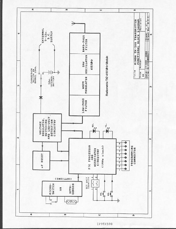
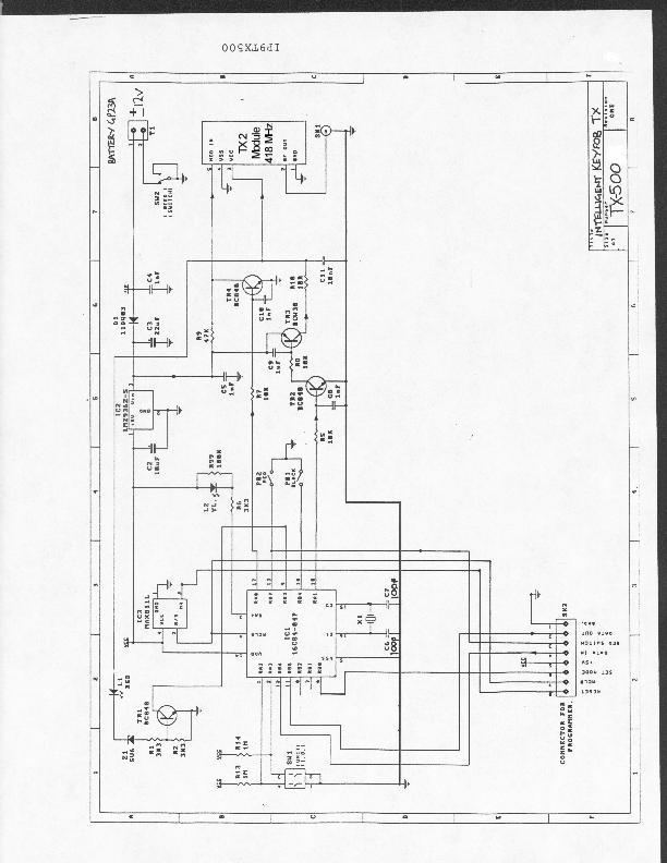
IP9TX500 TX-500 CIRCUIT DESCRIPTION This intelligent key-fob transmitter is compirsed of a small PCB on which there is a Radiometrix TX2 418 MHz saw oscilated transmitter module, a PIC 16C84-04P micro-processor with its assoicated components, a 2-way DIL switch, a 5 volt regulator, two push-buttons, red and yellow LEDs and various other discrete components. A 12 volt 33mA battery fitted into clips attached to the PCB provides power. A MINDA 'family code' is pre-programmed into the eeprom of the PIC micro-processor along with other user-selectable operating parameters by connecting a lead from an IBM compatible Personal Computer to the 8-way socket on the PCB. The unit's ID (1,2,3,or 4) is set up on the DIL switches and can be easily changed by the user. Pressing one of the two buttons on the top of the key-fob activates the transmitter. The PIC microprocessor causes battery power to be applied to the Radiometrix TX2 module. At this time, serially encoded data (including the status of the battery, and which button was pressed) to the modulation-input line of the TX mod ule. There are numerous programmable options available to the end user. These are fully described in the operator's manual.
Contact Information
Applicant
Richard B Snyder(President)
Test Firm
Radiation Sciences IncorporatedDaniel Signore
215-256-4133Fax: 215-256-0775
Technical Specifications
| # | Rule Parts | Frequency Range | Power Output |
|---|---|---|---|
| 1 | 15.231(e) | 418 MHz - 418 MHz | - |
Other Applications from Tactical Technologies Inc
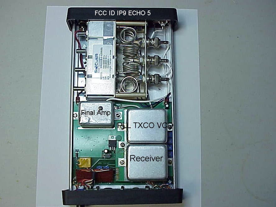
IP9ECHO5
Aug 21, 2005Repeater
Equipment Class
TNB - Licensed Non-Broadcast Station Transmitter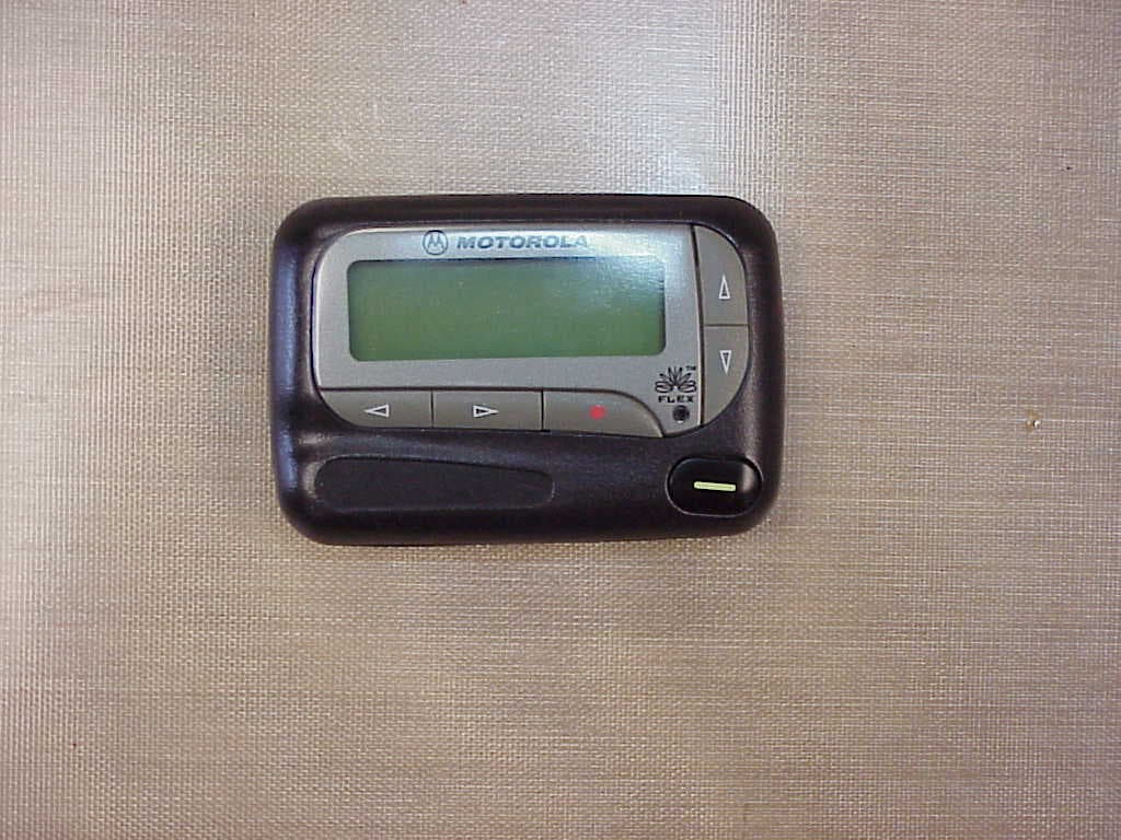
IP9801VI
Jun 22, 2005Synthesized VHF Surveillance Voice Transmitter
Equipment Class
TNT - Licensed Non-Broadcast Transmitter Worn on Body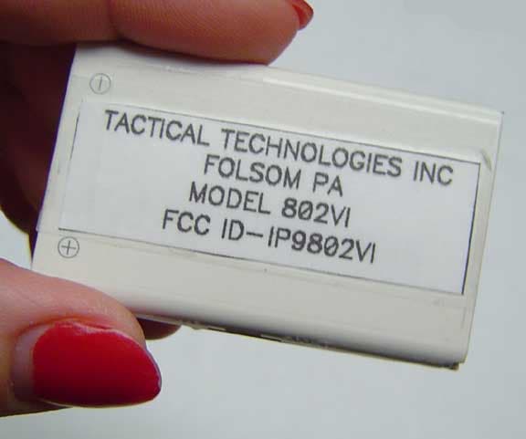
IP9802VI
May 05, 2005Synthesized VHF Surveillance Voice Transmitter
Equipment Class
TNT - Licensed Non-Broadcast Transmitter Worn on Body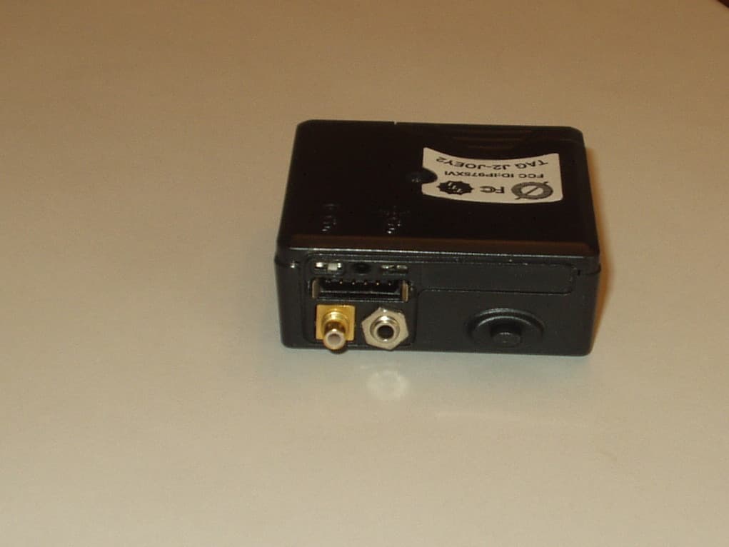
IP975XVI
Mar 28, 2005Synthesized VHF Surveillance Voice Transmitter
Equipment Class
TNT - Licensed Non-Broadcast Transmitter Worn on Body
IP9751V
Dec 01, 2002Law Enforcement Surveillance Transmitter
Equipment Class
LMS - Part 90 Location & Monitoring Transmitter