IUO9TB099DSSDDS Backup Library
Panasonic Healthcare Co., Ltd.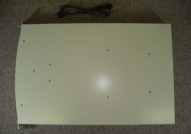
Click to zoom
Application Details
- Equipment Class
- JBP - Part 15 Class B Computing Device Peripheral
- Date of Grant
- Feb 23, 2004
- Application Purpose
- Original Equipment
- Date of Application
- Feb 23, 2004
- Equipment Note
- DDS Backup Library
- Country
- Japan
Documents & Files
Document Text
Text extracted from the exhibit documents filed with the FCC. Open a document above to read the original.
Users Manual
DDS BACKUP LIBRARY LKM-S121-S SAFETY INSTRUCTION MANUAL Please read through these instructions before operating this unit. SPECIFICATION SUMMARY GENERAL PERFORMANCE ➀ Power rating120 – 240 V ~ AUTO 0.5 – 0.28 A 50 / 60 Hz ➁ Dimensions (W x H x D)430 x 44 x 650 mm ➂ Weight11.5 kg [ typical ] ➃ Temperature Operating: 5~40 °CNon-operating: – 40~65 °C ➄ Humidity Operating: 20~80 %RHNon-operating: 0~90 %RH (Max. wet bulb temp. is 26 °C, Non-condensation)(Non-condensation, No cartridge tape) ENVIRONMENTAL CONDITIONS Weight and dimensions shown are approximate. Specifications are subject to change without notice. LMQT00644Printed in Japan Rev.A IMPORTANT SAFETY NOTICE LMQT00644 For USA CAUTION : Use shielded connecting cables in order to meet FCC emission limits and also to prevent interference to nearby radio and television reception. FEDERAL COMMUNICATIONS COMMISSION (FCC) RADIO FREQUENCY INTERFERENCE STATEMENT Class B Computing Device NOTE : This equipment has been tested and found to comply with the limits for a Class B digital device, pursuant to part 15 of the FCC Rules. These limits are designed to provide reasonable protection against harmful interference in a residential installation. This equipment generates, uses and can radiate radio frequency energy and , if not installed and used in accordance with the instructions, may cause harmful interference to radio communications. However, there is no guarantee that interference will not occur in a particular installation. If this equipment does cause harmful interference to radio or television reception, which can be determined by turning the equipment off and on, the user is encouraged to try to correct the interference by one or more of the following measures : - - Reorient or relocate the receiving antenna. - - Increase the separation between the equipment and receiver. - - Connect the equipment into an outlet on a circuit different from that to which the receiver is connected. - - Consult the dealer or an experienced radio/TV technician for help. FCC WARNING : Changes or modifications not expressly approved by the party responsible for compliance could void the user’s authority to operate the equipment. NOTICE (1) You may not reproduce or transcribe any part of this publication without permission. (2) We reserve the right to revise this document at any time without notice. (3) If you have any questions about this document, contact your sales representative. SAFETY NOTICE (1) To prevent fire or electric shock, do not expose this appliance to rain or moisture. (2) To avoid electric shock, do not attempt to disassemble the cabinet. (3) For pluggable equipment, the socket-outlet shall be installed near the equipment and shall be easily accessible. IMPORTANT SAFETY INSTRUCTIONS 1. Read all of these instructions. 2. Save these instructions for later use. 3. Follow all warnings and instructions marked on the product. 4.Unplug this product from the wall outlet before cleaning. Do not use liquid cleaners or aerosol cleaners. Use a damp cloth for cleaning. 5. Do not use this product near water. 6. Do not place this product on an unstable rack, cart, stand, or table. The product may fall, causing serious damage to the product. 7.This product should be operated from the type of power source indicated on the marking label. If you are not sure of the type of power available, consult your dealer or local power company. 8.This product is equipped with a 3-wire grounding type plug, a plug having a third (grounding) pin. This plug will only fit into a grounding-type power outlet. This is a safety feature. If you are unable to insert the plug into the outlet, contact your electrician to replace your obsolete outlet. Do not defeat the purpose of the grounding-type plug. 9.Do not allow anything to rest on the power cord. Do not locate this product where persons will walk on the cord. 10.If an extension cord is used with this product, make sure that the total of the ampere ratings on the products plugged into the extension cord do not exceed the extension cord ampere rating. Also, make sure that the total of all products plugged into the wall outlet does not exceed 15 amperes. 11.Never push objects of any kind into this product through cabinet slots as they may touch dangerous voltage points or short out parts that could result in a risk of fire or electric shock. Never spill liquid of any kind on the product. 12. Do not attempt to service this product yourself, as opening or removing covers may expose you to dangerous voltage points or other risks. Refer all servicing to service personnel. 13.Unplug this product from the wall outlet and refer servicing to qualified service personnel under the following conditions: A. When the power cord or plug is damaged or frayed. B. If liquid has been spilled into the product. C. If the product has been exposed to rain or water. D. If the product does not operate normally when the operating instructions are followed. Adjust only those controls that are covered by the operating instructions since improper adjustment of other controls may result in damage and will often require extensive work by a qualified technician to restore the product to normal operation. E. If the product has been dropped or the cabinet has been damaged. F.If the product exhibits a distinct change in performance, indicating a need for service. 14. Slots and openings in the cabinet and back or bottom are provided for ventilation and to ensure reliable operation of the product and to protect it from overheating. These openings must not be blocked or covered. KIT CONTENTS ■ DDS Backup Library Unit ■ Power Cable ■ Safety Instruction Manual Recommended Kits ◆ SCSI Interface Board Adaptec SCSI narrow ( ASC-29160/JA KIT ) ◆ Terminator (for SCSI daisy Chain) P/N: ACK-68 TERM KIT (1718100) ( by Adaptec ) ◆ Rack Please use the suitable rack for this Library. ( should be based on EIA standard ) ◆ Angle or Rail (Rail-Bracket) for Installing into Rack Please us…
Text truncated - open the document above for the full version.
Block Diagram
55 44 33 22 11 D D C C B B A A TitleSize Document Number Rev Date: Sheet of MKE 1.0 LKM-S121- S B 11 Tuesday, February 17, 2004 TitleSize Document Number Rev Date: Sheet of MKE 1.0 LKM-S121- B 11 Tuesday, February 17, 2004 TitleSize Document Number Rev Date: Sheet of MKE 1.0 LKM-S121- B 11 Tuesday, February 17, 2004 SCSI BUS LCD DisplayControl SwitchesFrontView BottomView Connector(for maintenance)Power LED(Green)Status LEDs Door Open Door Close CassetteOrigin2 CassetteOrigin TurntableOrigin SCSI Connector AC inlet,power switch and SCSI connector take out direct outside. SCSI BUSAC InletPower switch Foward/Back Origin Foward/Back Origin2 Up/Down Origin Cassette existence Clamp Open/Close U V W Hole Sensor +12V/+5V/+3.3V +12V/+5V/+3.3V +12V/+5V/+3.3V +12V/+5V +12V/+5V +12V/+5V +5V +12V/+5V +12V/+5V +5V/+3.3V +5V/+3.3V Caution Block Diagram Y440MHzY440MHz Eleveter PCBLMJB0711A CN1[1..26] CN9[1..3] CN10[1..3] CN3[1..4]CN6[1..3]CN2[1..4]CN7[1..3]CN8[1..3]CN4[1..4] Power SupplyPSMxxxx CN1[1..9]CN2[1..5]CN3[1..2] CN4[1..3] Connector CN1[1..3] LCD PCBLMJB0709A CN1[1..30] M9Turntable MotorM9Turntable Motor Turntable PCBLMJB0710A CN1[1..22] CN2[1..11] M1 Door Motor M1 Door Motor Cassette Sensor PCBLMJB0713A CN1[1..14] CN3[1..3]CN4[1..3] ABS PCBLMJB0721A CN3[1..136]CN2[1..5]CN8[1..2]CN7[1..6] CN1[1..68] CN6[1..3] M8 Cassette Clamp M8 Cassette Clamp Y327MHzY327MHz Y130MHzY130MHz Y230MHzY230MHz M4 Fan Motor M4 Fan Motor M3 Fan Motor M3 Fan Motor Loader Main PCBLMJB0707A CN1[1..26]CN2[1..80] CN8[1..9] CN7[1..4] CN5[1..3]CN10[1..3]CN9[1..3] Door PCBLMJB0714A CN4[1..6] CN2[1..2]CN5[1..3]CN3[1..3] CN1[1..16] Front PCBLMJB0722A CN1[1..6] M5 Fan Motor M5 Fan Motor Cassette Motor PCBLMJB0712A CN1[1..12] CN2[1..2] M6 Eleveter Foward/Back M6 Eleveter Foward/Back Bottom PCBLMJB0708A CN5[1..16]CN7[1..30] CN9[1..6] CN15[1..3] CN3[1..12] CN4[1..14] CN11[1..4] CN12[1..15] CN1[1..4]CN6[1..4]CN8[1..22]CN2[1..80] CN14[1..3] M7 Eleveter Up/Down M7 Eleveter Up/Down DDS DriveDAT72 CN1001[81..84] CN1006[1..6]CN1010[1..15] CN1001[1..68] M2 Cassette Guard Motor M2 Cassette Guard Motor
Cover Letter(s)
Matsushita Kotobuki Electronics Industries Ltd. Storage Products Business Unit Address: 2131-1 Minamigata, Kawauchi-cho, Onsen, Ehime 791 – 0395 Japan attn:Reviewing Engineer Federal Communications Commission 7435 Oakland Mills Road Columbia, MD 21046 RE: LETTER OF AGENT AUTHORIZATION To Whom It May Concern: We, the undersigned, hereby authorize MET Laboratories, Inc. to act on our behalf in all matters relating to application for equipment authorization, including the signing of all documents relating to these matters. We also hereby certify that no party to the application authorized hereunder is subject to the denial of benefits, including FCC benefits, pursuant to Section 5301 of the Anti-Drug Abuse Act of 1988,21 U.S.C.853(a). This agreement expires one year from the current date. Sincerely, Date : February 20, 2004 Signature : Printed name : Shinji Yamauchi Company name : Matsushita Kotobuki Electronics Ind.,Ltd. Storage Products Business Unit Legal Affairs Team.
Operational Description
Operational Description of DDS Backup Library FCC ID: IUO9TB099DSS Model No.: LKM-S121-S Backup Library, LKM-S121-S, is a storage device using DAT (Digital Audio Tape) for large data back up. It can equip maximum 24 DATs for storing about 1,700 GB (in the case of storing compression data). Backup Library contains an autoloader that loads DDS (DAT Data Storage) drive and DAT automatically, controller, buffer memory circuit board and power unit in the 44 mm height chassis. Front of chassis is plastic and others are irons. Each magazine that can store three DATs is placed in eight garages that are placed circumferentially around the DDS in the autoloader. Each garage rotates by motor drive to load the DAT into DDS drive.
Test Report
Matsushita Kotobuki Electronics Industries Ltd. Storage Products Business Unit Address: 2131-1 Minamigata, Kawauchi-cho, Onsen, Ehime 791 – 0395 Japan Page 1 of 18 pages TEST REPORT REPORT NUMBER: MKM04F-001 APPLICANT: Matsushita Kotobuki Electronics Industries, Ltd. MODEL NUMBER: LKM-S121-S FCC ID: IUO9TB099DSS Regulation: FCC Part15B Class B Conducted Emission Test Radiated Emission Test Matsushita Kotobuki Electronics Ind., Ltd. Storage Products Business Unit 2131-1 Minamigata, Kawauchi-cho, Onsen-gun, Ehime-ken, 791-0395 Japan Tel.: +81 89 966 2111 Fax.: +81 89 966 5733 Report No. MKM04F-001 FCC ID : IUO9TB099DSS Page 2 of 18 pages TABLE OF CONTENTS Page SECTION 1.TEST CERTIFICATION3 SECTION 2.EQUIPMENT UNDER TEST5 SECTION 3.SUPPORT EQUIPMENT USED6 SECTION 4.CABLE(S) USED 7 SECTION 5.CONSTRUCTION OF EQUIPMENT 9 SECTION 6.OPERATING CONDITIONS10 SECTION 7.TEST PROCEDURE(S) 11 SECTION 8.EVALUATION OF TEST RESULTS12 SECTION 9.PHOTOGRAPHS OF TEST SET-UP 16 SECTION 10. INSTRUMENTS USED FOR TEST17 SECTION 11. PRECISION18 SECTION 12. VALIDITY OF TEST REPORT18 Report No. MKM04F-001 FCC ID : IUO9TB099DSS Page 3 of 18 pages SECTION 1. TEST CERTIFICATION APPLICANT INFORMATION Company: Matsushita Kotobuki Electronics Industries, Ltd. Address: 2131-1 Minamigata, Kawauchi-cho, Onsen-gun, Ehime-ken, 791-0395 Japan GRANTEE INFORMATION Company: Matsushita Kotobuki Electronics Industries, Ltd. Division / Section : Storage Products Business Unit Legal Affairs Team. Address: 2131-1 Minamigata, Kawauchi-cho, Onsen-gun, Ehime-ken, 791-0395 Japan Telephone number: +81 89 966 2111 Fax number : +81 89 966 5733 Contact person: Shinji Yamauchi DESCRIPTION OF TEST ITEM Kind of equipment: DDS BACKUP LIBRARY Trademark: Matsushita Kotobuki FCC ID : IUO9TB099DSS Model number : LKM-S121-S Serial number: AA411300M00001 Report No. MKM04F-001 FCC ID : IUO9TB099DSS Page 4 of 18 pages TEST PERFORMED FCC Registration No.: 90793 Test started : February 16, 2004 Test completed: February 17, 2004 Purpose of test : FCC Docket 87-389 Regulation: FCC Part 15B Class B Unintentional Radiators Test setup: ANSI C63.4 -1992 Report file number: MKM04F-001 Report issue date: February 20, 2004 Test engineer: Shinji Yamauchi Report approved by : Hisayuki Honda [ Manager ] This equipment complies with above standard or regulation under the test condition or test configuration shown on this test report. Report No. MKM04F-001 FCC ID : IUO9TB099DSS Page 5 of 18 pages SECTION 2. EQUIPMENT UNDER TEST The equipment under test (EUT) consists of the following equipment. Indication in the following left side column corresponds to section 5. SymbolItemModel No. Serial No. FCC IDManufacturer A) DDS BACKUP LKM-S121-S AA411300M00001 IUO9TB099DSS Matsushita Kotobuki LIBRARY Electronics Ind., Ltd. Power ratings of EUT : AC 120V-240V,50Hz/60Hz, 0.5A-0.28A 2.1 Port(s) / Connector(s) : SCSI Half pitch Connector (68pin) SCSI Half pitch Connector (68pin) 2.2 Oscillator(s) / Crystal(s) : Oscillator OperatingBoard name Remarks Frequency 30 MHz 15 MHz Main PCBCPU 30 MHz 30 MHz Main PCBGate Array 30 MHz 15 MHz Buffer PCB CPU 30 MHz 30 MHz Buffer PCB Gate Array 27 MHz 126 MHz (*) DAT72 MainPCB Channel_clock 40 MHz 40 MHz DAT72 MainPCB Logic_clock 40 MHz 40 MHz DAT72 MainPCB SCSI_clock (*) Highest frequency Report No. MKM04F-001 FCC ID : IUO9TB099DSS Page 6 of 18 pages SECTION 3. SUPPORT EQUIPMENT USED The EUT has been supported by the following equipment during these tests. Indication in the following left side column corresponds to section 5. SymbolItemModel No. Serial No.FCC IDManufacturer B) Interface CardAHA-2940UW BF0C8240193 FGT2940UW ADAPTEC C) Host Computer OptiPlex GXa SP4BX Declaration ofDELL DCS Conformity D) Color Display XC-1429C 009133290 BGB9J5XC-1429C MITSUBISHI E) Printer 3630A 3040A00351BSD8533630AHEWLETT PACKARD F) KeyboardG9900 J434518 GYUR61SKGATEWAY G) Mouse Mouse Port 01171231 C3KKMP3 Microsoft CompatibleMouse2.1A H) DAT Data LKM-DE4H-7 250412 None Matsushita Storage DriveKotobuki Report No. MKM04F-001 FCC ID : IUO9TB099DSS Page 7 of 18 pages SECTION 4. CABLE(S) USED The following cable(s) was used for testing. Indication number in the following left side column corresponds to section 5. NumberNameLengthShield From To 1)SCSI cable 2.0 mYes Interface Card DDS BACKUP Metal connector LIBRARY 2)SCSI cable 2.0 mYes DDS BACKUP LIBRARY DAT Data Storage Metal connector Drive 3)Parallel I/F cable 1.5 mYes Host Computer Printer Metal connector 4)Keyboard I/F cable 1.9 mYes Host Computer Keyboard Metal connector 5)Mouse cable 1.9 mNone Host Computer Mouse Metal connector 6)Video Signal1.4 mYes Host Computer Color Display cable Metal connector 7) Power cord for 1.7 m None EUT Power Source EUT 8) Power cord for 1.7 m None DAT Data Storage Power Source DAT Data Storage Drive Drive 9) Power cord for 1.3 m None Host Computer Power Source Host Computer Report No. MKM04F-001 FCC ID : IUO9TB099DSS Page 8 of 18 pages The following cable(s) was used for testing. Indication number in the following left side column corresponds to section 5. NumberNameLengthShieldFromTo 10) Power cord for 1.5 m None Color Display Power Source Color Display 11)Power cord for Printer2.0 mNonePrinterAC Adapter 12)Power cord for Printer2.0 mNoneAC AdapterPower Source Report No. MKM04F-001 FCC ID : IUO9TB099DSS Page 9 of 18 pages SECTION 5. CONSTRUCTION OF EQUIPMENT The construction of EUT during testing is as follows. System configuration * : EUT Symbol or numbers assigned to equipment or cables on this diagram are corresponded to the symbols or numbers assigned to equipment or cables on tables in Sections 2 to 4. G)Mouse 12 3 4 5 6 78 9 10 11 12 120V AC 60Hz 120V AC 60Hz 120V AC 60Hz 120V AC 60Hz 120V AC 60Hz B)Interface Card C)Host Computer A)DDS Backup Library * H)DAT Data Storage Drive E)Printer F) Keyboard 20V AC60Hz AC Adapter D)Color Display Report No. MKM04F-001 FCC ID : IUO9TB099DSS Page 10 of 18 pages SECTION 6. OPERATING CONDITIONS The EUT has been operated under the follow…
Text truncated - open the document above for the full version.
Test Setup Photos
Report No. MKM04F-001 FCC ID : IUO9TB099DSS Page 16 of 18 pages SECTION 9. PHOTOGRAPHS OF TEST SET-UP Test setup in accordance with ANSI C63.4-1992 9.1 Conducted Emission Test Front View Rear view 9.2 Radiated Emission Test Front View Rear view Note : Maintaining 10cm spacing between all the equipment cabinets.
Contact Information
Applicant
Shinji Yamauchi(Legal Affairs Team)
Test Firm
ETL SEMKO Japan K.K., Tochigi EMC SiteYuji Ohashi
Technical Specifications
| # | Rule Parts | Frequency Range | Power Output |
|---|---|---|---|
| 1 | 15B | - | - |
Other Applications from Panasonic Healthcare Co., Ltd.
IUO9TB098DSS
Aug 09, 2003S-AIT Tape Drive Unit
Equipment Class
JBP - Part 15 Class B Computing Device PeripheralIUO9TB097DSS
Aug 09, 2003S-AIT Tape Drive Unit
Equipment Class
JBP - Part 15 Class B Computing Device Peripheral
IUO9TB096CRB
Mar 31, 2003DVD-ROM Drive
Equipment Class
JBP - Part 15 Class B Computing Device Peripheral
IUO9TB095DSS
Sep 18, 2002DDS Storage Device
Equipment Class
JBP - Part 15 Class B Computing Device PeripheralIUO9TB094CRB
Feb 21, 2002DVD-ROM & CD-R/RW Drive
Equipment Class
JBP - Part 15 Class B Computing Device Peripheral