IWK-CG304Wireless Coating Thickness Tester
FLIR Commercial Systems, Inc.
Click to zoom
Application Details
- Equipment Class
- DSS - Part 15 Spread Spectrum Transmitter
- Date of Grant
- Jun 19, 2014
- Application Purpose
- Original Equipment
- Date of Application
- Jun 19, 2014
- Equipment Note
- Wireless Coating Thickness Tester
- Frequency Range
- 2402.00000000 - 2480.00000000
- Country
- United States
Documents & Files
Document Text
Text extracted from the exhibit documents filed with the FCC. Open a document above to read the original.
Users Manual
USER GUIDE Coating Thickness Tester With Bluetooth® Model CG304 CG304-EU-EN v1.0 6/14 2 Introduction Congratulations on your purchase of the Extech CG304 Coating Thickness Tester. The CG304 is a portable meter designed for non‐invasive coating thickness measurements with automatic recognition of the material under test. The meter uses two measurement methods: magnetic induction (for ferrous metal substrates) and eddy current (for non‐ferrous metal substrates). The Bluetooth® feature wirelessly transmits measurement data to a PC for further analysis and to generate report documentation. Proper use and care of this meter will provide many years of reliable service . Description Meter Description 1. LCD display 2. Power key 3. Probe 4. ARROW buttons Note: Battery compartment on rear of meter Display Icon Description NFe Non‐ferrous metals Fe Ferrous metals AUTO Automatic substrate recognition F or N Calibration icons DIR DIRECT mode GRO1...4 GROUP Mode number μm Micrometers unit of measure mils mils = millimeters * 2.54/100 mm Millimeters unit of measure AVG Average reading MIN Minimum reading MAX Maximum reading SDEV Standard Deviation reading NO Number of data points Low battery Note: The unit of measure icon flashes when in the CONTINUOUS mode of operation. The unit of measure icon is stable when in the SINGLE mode of operation. 2 4 1 3 CG304-EU-EN v1.0 6/14 3 Quick Start Instructions Meter Power Press the power button to switch the meter ON. The display will switch ON. If the display does not switch ON, install or replace the batteries. Measurements Use the film references and zero reference metal substrates to learn how the meter operates before moving to a professional application. The round metal substrate is the ferrous (magnetic) substrate and the rectangular shaped metal substrate is the non‐ferrous (non‐magnetic) substrate. The meter automatically senses ferrous and non‐ferrous substrates. 1. Place a reference film (250μm, for example) on the round, ferrous substrate. 2. Place the spring‐loaded meter sensor against the reference film. 3. In the single mode the meter will emit an audible tone indicating that the measurement has been taken. 4. In the continuous mode the display will continually measure and update the display 5. The LCD will show the reading (250μm) at the center of the display area. 6. A typical display will also show the following: NO = 1 (reading number one) on the lower left of the LCD AVG = 250μm (running average) on the lower right DIR = DIR mode of operation on the upper left Fe = Ferrous substrate on the upper right of the LCD Experiment with the remaining reference films and the substrate before using the meter professionally. Automatic Power OFF In order to conserve battery life, the meter will automatically turn off after approximately 10 minutes. To defeat this feature use the programming menu detailed in the next section (menu parameter AUTO POWER OFF under OPTIONS). DIR um AVG=250NO=1 250 Fe CG304-EU-EN v1.0 6/14 4 Programming Menu The meter can be configured and calibrated through simple button presses in the programming menu. Press the LEFT button to access the menu and refer to the menu ‘tree’ below. The menu uses UP/DOWN, LEFT/RIGHT presses for navigation and selection. In the table below the factory default settings are in bold with an asterisk. Each parameter is explained in detail in the subsequent sections. Top level Sub level 1 Sub level 2 Notes STATISTICAL VIEW AVG* Average of a series of readings MIN Lowest of a series of readings MAX Highest of a series of readings NO Number of sampled readings SDEV Standard deviation of a series OPTIONS Measure mode Single* One reading at a time Continuous Continuous measurements Working mode Direct* Readings are not stored in groups Group 1...4 Store readings in groups Probe used Auto* Meter automatically selects mode Fe Ferrous measurement mode No Fe Non‐ferrous measurement mode Unit settings μm* Micrometers mils Mils = mm * 2.54 / 100 mm Millimeters Backlight ON* Enables backlight operation OFF Disables backlight operation LCD Statistics AVG* Average of a series of readings MAX Lowest of a series of readings MIN Highest of a series of readings SDEV Standard deviation of a series Auto Power OFF Enable* Allows auto power off to operate Disable Defeats the auto power off feature LIMIT Limit settings High Limit High Alarm alerts user when reached Low Limit Low Alarm alerts user when reached Delete Limits Clear the alarm limit values DELETE Current Data Delete current data All Data Delete all stored data Group Data Delete data stored data plus alarm and calibration data MEASUREMENT VIEW View stored data in all groups CALIBRATION Enable Allow calibration access Disable Lock out the calibration mode Delete Zero N Clear the zero cal. data (non‐ferrous) Delete Zero F Clear the zero cal. data (ferrous) NOTE: Disable the Auto Power OFF feature before lengthy programming to avoid inconvenient automatic power down while programming. CG304-EU-EN v1.0 6/14 5 STATISTICAL VIEWS Menu 1. Press the LEFT button to access the programming menu 2. Press the LEFT button to choose STATISTCAL VIEW 3. Use the UP and DOWN buttons to scroll through the AVERAGE, MINIMUM, MAXIMUM, NUMBER OF DATA, and SDEV (Standard Deviation) values for the stored readings. 4. ‘NO DATA’ will display if no readings are available for the meter to analyze. Stored readings will clear when the meter powers down unless the GROUP feature is used (refer to GROUP function explanation later in this section). 5. Press the BACK and then the ESC soft‐keys to return to the normal operating mode. OPTIONS Menu 1. Press the LEFT button to access the programming menu 2. Use the UP/DOWN button to scroll down to OPTIONS 3. Press LEFT button to select OPTIONS 4. Use the UP and DOWN buttons to scroll to the MEASURE MODE, WORKING MODE, PROBE USED, UNIT SETTINGS, BACKLIGHT, LCD STATISTICS, AND AUTO POWER OFF parameters. Use the LEFT soft‐key to select the desired par…
Text truncated - open the document above for the full version.
Attestation Statements
Page 1 of 2 Applicant FLIR Commercial Systems, Inc. FCC ID IWK-CG304 Frequency Hopping system filing requirements Requirements EUT Condition Comply Pseudorandom Frequency Hopping Sequence Describe how the hopping sequence is generated. Provide an example of the hopping sequence channels, in order to demonstrate that the sequence meets the requirement specified in the definition of a frequency hopping spread spectrum system, found in Section 2.1. The channel is represented by a pseudo-random hopping sequence hopping through the 79 RF channels. The hopping sequence is unique for the piconet and is determined by the Bluetooth device address of the master; the phase in the hopping sequence is determined by the Bluetooth clock of the master. The channel is divided into time slots where each slot corresponds to an RF hop frequency. Consecutive hops correspond to different RF hop frequencies. The nominal hop rate is 1 600 hops/s. Example of a 79 hopping sequence in data mode: 40, 21, 45, 23, 42, 53, 46, 55, 48, 31, 51, 35, 50, 65, 54, 67, 56, 37, 60, 39, 58, 69, 62, 77, 64, 25, 68, 27, 66, 57, 70, 59, 72, 29, 76, 33, 74, 61, 78, 63, 01, 41, 05, 43, 03, 73, 07, 75, 09, 44, 15, 47, 11, 71, 13, 00, 64, 49, 66, 53, 68, 02, 70, 06, 01, 52, 03, 55, 05, 04 Y Equal Hopping Frequency Use Describe how each individual EUT meets the requirement that each of its hopping channels is used equally on average (e.g., that each new transmission event begins on the next channel in the hopping sequence after the final channel used in the previous All Bluetooth units participating in the piconet are time and hop-synchronized to the channel. Y Page 2 of 2 transmission event). System Receiver Input Bandwidth Describe how the associated receiver(s) complies with the requirement that its input bandwidth (either RF or IF) matches the bandwidth of the transmitted signal. Each channel bandwidth is 1 MHz Y Equipment Description 15.247(a)(1) that the rx input bandwidths shift frequencies in synchronization with the transmitted 15.247(g): In accordance with the Bluetooth Industry Standard, the system is designed to comply with all of the regulations in Section 15.247 when the transmitter is presented with a continuous data (or information) system. 15.247(h): In accordance with the Bluetooth Industry Standard, the system does not coordinate it channels selection/ hopping sequence with other frequency hopping systems for the express purpose of avoiding the simultaneous occupancy of individual hopping frequencies by multiple transmitters. Y
External Photos
External Photo
Internal Photos
Internal Photo
RF Exposure Info
CG304 RF-EXPOSURE ASSESSMENT FCC ID: IWK-CG304 The max. tune up power is: 4dBm, 3mW. The 1-g and 10-g SAR test exclusion thresholds for 100 MHz to 6 GHz at test separation distances ≤ 50 mm are determined by: [(max. power of channel, including tune-up tolerance, mW)/(min. test separation distance, mm)] · [√f(GHz)] ≤ 3.0 for 1-g SAR and ≤ 7.5 for 10-g extremity SAR, where • f(GHz) is the RF channel transmit frequency in GHz • Power and distance are rounded to the nearest mW and mm before calculation • The result is rounded to one decimal place for comparison • 3.0 and 7.5 are referred to as the numeric thresholds in the step 2 below Assessment results: PASS FCC SAR test exclusion condition: 3[mW]/5.0[mm]* [√2.48(GHz)] =0.9< 7.5
Test Report
FCC TEST REPORT For Coating Thickness Tester Model Number: CG304 FCC ID: IWK-CG304 Report Number : WT148001393 Test Laboratory : Shenzhen Academy of Metrology and Quality Inspection National Digital Electronic Product Testing Center Site Location : No.4 TongFa Road, Xili Town, Nanshan District, Shenzhen, China Tel : 0086-755-86009898 Fax : 0086-755-86009898-31396 Web : www.smq.com.cn Report No.:WT148001393 Page 2 of 59 Test report declaration Applicant : FLIR Commercial Systems, Inc. Address : 9 Townsend West Nashua New Hampshire 03063 United States Manufacturer : SHENZHEN EVERBEST MACHINERY INDUSTRY CO., LTD Address : 19 th Building, 5 th Region, Baiwangxin Industrial Park, Songbai Rd., Baimang, Xili, Nanshan, Shenzhen, China EUT Description : Coating Thickness Tester Model No : CG304 Trade mark : EXTECH FCC ID : IWK-CG304 Test Standards: FCC Part 15 (10-1-12 Edition) ANSI C63.4-2009 The EUT described above is tested by Shenzhen Academy of Metrology and Quality Inspection EMC Laboratory to determine the maximum emissions from the EUT. Shenzhen Academy of Metrology and Quality Inspection EMC Laboratory is assumed full responsibility for the accuracy of the test results. The test data, data evaluation, test procedures, and equipment configurations shown in this report were made in accordance with the procedures given in ANSI C63.4 (2009) and the energy emitted by the sample EUT tested as described in this report is in compliance with FCC Rules Part 15.207, 15.209 and 15.247. The test report is valid for above tested sample only and shall not be reproduced in part without written approval of the laboratory. Project Engineer: Date: May.07,2014 (Chen Qichun) May.07,2014 Checked by: Date: (Yang Dongping) May.07,2014 Approved by: Date: (Lin Bin) Report No.:WT148001393 Page 3 of 59 TABLE OF CONTENTS TEST REPORT DECLARATION ........................................................................................................ 2 1. TEST RESULTS SUMMARY ................................................................................................... 5 2. GENERAL INFORMATION ...................................................................................................... 6 2.1. Report information .......................................................................................................... 6 2.2. Laboratory Accreditation and Relationship to Customer ......................................... 6 2.3. Measurement Uncertainty ............................................................................................. 7 3. PRODUCT DESCRIPTION ...................................................................................................... 8 3.1. EUT Description .............................................................................................................. 8 3.2. Related Submittal(s) / Grant (s) ................................................................................... 8 3.3. Block Diagram of EUT Configuration .......................................................................... 8 3.4. Operating Condition of EUT.......................................................................................... 8 3.5. Support Equipment List ................................................................................................. 9 3.6. Test Conditions ............................................................................................................... 9 3.7. Special Accessories ....................................................................................................... 9 3.8. Equipment Modifications ............................................................................................... 9 4. TEST EQUIPMENT USED ..................................................................................................... 10 5. CONDUCTED DISTURBANCE TEST .................................................................................. 11 5.1. Test Standard and Limit .............................................................................................. 11 5.2. Test Procedure ............................................................................................................. 11 5.3. Test Arrangement ......................................................................................................... 11 5.4. Test Data ....................................................................................................................... 11 6. RADIATED DISTURBANCE TEST ....................................................................................... 12 6.1. Test Standard and Limit .............................................................................................. 12 6.2. Test Procedure ............................................................................................................. 12 6.3. Test Arrangement ......................................................................................................... 12 6.4. Test Data ....................................................................................................................... 13 7. 20DB BANDWIDTH MEASUREMENT ................................................................................. 20 7.1. Limits of 20dB Bandwidth Measurement .................................................................. 20 7.2. Test Procedure ............................................................................................................. 20 7.3. Test Setup ..................................................................................................................... 20 Report No.:WT148001393 Page 4 of 59 7.4. Test Data ....................................................................................................................... 20 8. CARRIER FREQUENCY SEPARATION MEASUREMENT ............................................. 25 8.1. Limits of Carrier Frequency Separation Measurement ........................................…
Text truncated - open the document above for the full version.
Test Setup Photos
Radiated Disturbance
Contact Information
Applicant
Mark Sultzbach(QA Administrator)
Test Firm
shenzhen academy of metrology & quality inspectionpeter lin
[email protected]86-755-86009898
Technical Specifications
| # | Rule Parts | Frequency Range | Power Output |
|---|---|---|---|
| 1 | 15C | 2.40 GHz - 2.48 GHz | 1.00 mW |
Other Applications from FLIR Commercial Systems, Inc.
IWK-DT500
Jan 15, 2015Laser Distance Meter
Equipment Class
DSS - Part 15 Spread Spectrum Transmitter
IWK-GX900-GX930
Aug 17, 2014Multimeter with Bluetooth
Equipment Class
DSS - Part 15 Spread Spectrum Transmitter
IWK-EX850
May 12, 2014Wireless Clamp Meter
Equipment Class
DSS - Part 15 Spread Spectrum Transmitter
IWK-MO270X
Feb 19, 2012Wireless Moisture Meter
Equipment Class
DXX - Part 15 Low Power Communication Device Transmitter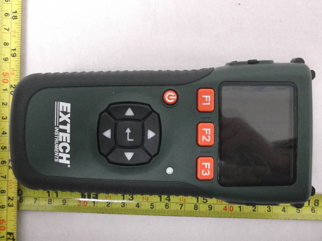
IWK-EX3000
Feb 13, 2012Wireless Receiver
Equipment Class
DXX - Part 15 Low Power Communication Device Transmitter