IWK-EX850Wireless Clamp Meter
FLIR Commercial Systems, Inc.
Click to zoom
Application Details
- Equipment Class
- DSS - Part 15 Spread Spectrum Transmitter
- Date of Grant
- May 12, 2014
- Application Purpose
- Original Equipment
- Date of Application
- May 12, 2014
- Equipment Note
- Wireless Clamp Meter
- Frequency Range
- 2402.00000000 - 2480.00000000
- Country
- United States
Documents & Files
Document Text
Text extracted from the exhibit documents filed with the FCC. Open a document above to read the original.
Users Manual
USER GUIDE Extech EX850 True RMS 1000 Amp Clamp Meter Bluetooth TM and Android TM ready Patented EXTECH INSTRUMENTS EX850-EN V2.3 5/14 2 Introduction Congratulations on your purchase of the Extech EX850 CAT IV True RMS 1000A Clamp Meter. This meter includes a Bluetooth TM module and is Android TM ready. The EX850 measurement functions include AC/DC Voltage, AC/DC Current, Resistance, Capacitance, Frequency, Duty Cycle, Diode Test, Continuity, Type k thermocouple thermometer plus Non‐Contact IR Temperature. Proper use and care of this meter will provide many years of reliable service. Visit www.extech.com for more information. Safety International Safety Symbols This symbol, adjacent to another symbol or terminal, indicates the user must refer to the manual for further information. This symbol, adjacent to a terminal, indicates that, under normal use, hazardous voltages may be present Double insulation SAFETY NOTES Do not exceed the maximum allowable input range of any function. Do not apply voltage to meter when resistance function is selected. Set the function switch OFF when the meter is not in use. Remove the battery if meter is to be stored for longer than 60 days. WARNINGS Set function switch to the appropriate position before measuring. When measuring volts do not switch to current/resistance modes. Do not measure current on a circuit whose voltage exceeds 600V. When changing ranges always disconnect the test leads from the circuit under test. Function Maximum Input A AC, ADC 1000A DC/AC V DC, V AC 1000V DC/AC Resistance, Capacitance, Frequency, Diode Test 250V DC/AC Type K Temperature 60V DC, 24V AC EXTECH INSTRUMENTS EX850-EN V2.3 5/14 3 CAUTIONS Improper use of this meter can cause damage, shock, injury or death. Read and understand this user manual before operating the meter. Always remove the test leads before replacing the battery or fuses. Inspect the condition of the test leads and the meter itself for any damage before operating the meter. Repair or replace any damage before use. Use great care when making measurements if the voltages are greater than 25VAC rms or 35VDC. These voltages are considered a shock hazard. Always discharge capacitors and remove power from the device under test before performing Diode, Resistance or Continuity tests. Voltage checks on electrical outlets can be difficult and misleading because of the uncertainty of connection to the recessed electrical contacts. Other means should be used to ensure that the terminals are not "live". If the equipment is used in a manner not specified by the manufacturer, the protection provided by the equipment may be impaired. This device is not a toy and must not reach children’s hands. It contains hazardous objects as well as small parts that the children could swallow. In case a child swallows any of them, please contact a physician immediately Do not leave batteries and packing material lying around unattended; they can be dangerous for children if they use them as toys In case the device is going to be unused for an extended period of time, remove the batteries to prevent them from draining Expired or damaged batteries can cause cauterization on contact with the skin. Always, therefore, use suitable hand gloves in such cases See that the batteries are not short‐circuited. Do not throw batteries into the fire. Do not directly view or direct the laser pointer at an eye. Low power visible lasers do not normally present a hazard, but may present some potential for hazard if viewed directly for extended periods of time EXTECH INSTRUMENTS EX850-EN V2.3 5/14 4 Description Meter Description 1. Current clamp 2. Clamp opening trigger 3. Data Hold Button 4. Mode 5. Peak 6. Range 7. DCA Zero 8. MIN/MAX 9. Backlit LCD Display 10. Test lead input jacks 11. IR thermometer and laser pointer (rear) 12. Bluetooth SEND/Backlight Button 13. Laser pointer button 14. Function switch Display icons Description HOLD Data Hold Minus sign Negative reading display 0 to 3999 Measurement display digits ZERO Zero P Peak value AUTO Auto Range mode DC/AC Direct / Alternating Current MAX Max reading MIN Min reading Low battery mV or V Milli‐volts or Volts (Voltage) Ω Ohms (Resistance) A Amperes (Current) F Farad (Capacitance) Hz Hertz (Frequency) o F and o C Fahrenheit and Celsius units (Temperature) n, m, μ, M, k Unit of measure prefixes: nano, milli, micro, mega, and kilo ) ) ) Continuity test Diode test Laser pointer Bluetooth active symbol EXTECH INSTRUMENTS EX850-EN V2.3 5/14 5 Operation NOTES: Read and understand all Warning and Caution statements in this operation manual prior to using this meter. Set the function select switch to the OFF position when the meter is not in use. AC Current Measurements WARNING: Ensure that the test leads are disconnected from the meter before making current clamp measurements. 1. Set the Function switch to the AAC or ADC range 2. Press the trigger to open the jaw. Fully enclose only one conductor. For optimum results, center the conductor in the jaw. 3. The clamp meter LCD will display the reading. DCA ZERO The DC Zero feature removes offset values and improves accuracy for DC current measurements. To perform a zero, select ADC and with no conductor in the jaw: 1. Press the DC ZERO button to zero the display. “ZERO” will appear in the display. The offset value is now stored and remo ved from all measurements. 2. To view the stored value, press the DC ZERO button. “ZERO” will flash and the stored value will be displayed. 3. To exit this mode, press and Hold the ZERO button until “ZERO” is no longer in the display. AC/DC Voltage Measurements 1. Insert the black test lead into the negative COM terminal and the red test lead into the positive V terminal. 2. Set the function switch to the VAC or VDC position. 3. Use the MODE button to select AC or DC Voltage. 4. Connect the test leads in parallel to the circuit under test. 5. Read the voltage measurement on the LCD d…
Text truncated - open the document above for the full version.
Cover Letter(s)
Page 1 of 2 Applicant FLIR Commercial Systems, Inc. FCC ID IWK-EX850 Frequency Hopping system filing requirements Requirements EUT Condition Comply Pseudorandom Frequency Hopping Sequence Describe how the hopping sequence is generated. Provide an example of the hopping sequence channels, in order to demonstrate that the sequence meets the requirement specified in the definition of a frequency hopping spread spectrum system, found in Section 2.1. The channel is represented by a pseudo-random hopping sequence hopping through the 79 RF channels. The hopping sequence is unique for the piconet and is determined by the Bluetooth device address of the master; the phase in the hopping sequence is determined by the Bluetooth clock of the master. The channel is divided into time slots where each slot corresponds to an RF hop frequency. Consecutive hops correspond to different RF hop frequencies. The nominal hop rate is 1 600 hops/s. Example of a 79 hopping sequence in data mode: 40, 21, 45, 23, 42, 53, 46, 55, 48, 31, 51, 35, 50, 65, 54, 67, 56, 37, 60, 39, 58, 69, 62, 77, 64, 25, 68, 27, 66, 57, 70, 59, 72, 29, 76, 33, 74, 61, 78, 63, 01, 41, 05, 43, 03, 73, 07, 75, 09, 44, 15, 47, 11, 71, 13, 00, 64, 49, 66, 53, 68, 02, 70, 06, 01, 52, 03, 55, 05, 04 Y Equal Hopping Frequency Use Describe how each individual EUT meets the requirement that each of its hopping channels is used equally on average (e.g., that each new transmission event begins on the next channel in the hopping sequence after the final channel used in the previous All Bluetooth units participating in the piconet are time and hop-synchronized to the channel. Y Page 2 of 2 transmission event). System Receiver Input Bandwidth Describe how the associated receiver(s) complies with the requirement that its input bandwidth (either RF or IF) matches the bandwidth of the transmitted signal. Each channel bandwidth is 1 MHz Y Equipment Description 15.247(a)(1) that the rx input bandwidths shift frequencies in synchronization with the transmitted 15.247(g): In accordance with the Bluetooth Industry Standard, the system is designed to comply with all of the regulations in Section 15.247 when the transmitter is presented with a continuous data (or information) system. 15.247(h): In accordance with the Bluetooth Industry Standard, the system does not coordinate it channels selection/ hopping sequence with other frequency hopping systems for the express purpose of avoiding the simultaneous occupancy of individual hopping frequencies by multiple transmitters. Y
External Photos
External Photo
ID Label/Location Info
FCC/IC label here ETL label here
Internal Photos
Internal Photo
RF Exposure Info
EX850 RF-EXPOSURE ASSESSMENT FCC ID: IWK-EX850 The max. tune up power is: 4dBm, 2.51mW. The 1-g and 10-g SAR test exclusion thresholds for 100 MHz to 6 GHz at test separation distances ≤ 50 mm are determined by: [(max. power of channel, including tune-up tolerance, mW)/(min. test separation distance, mm)] · [√f(GHz)] ≤ 3.0 for 1-g SAR and ≤ 7.5 for 10-g extremity SAR, where • f(GHz) is the RF channel transmit frequency in GHz • Power and distance are rounded to the nearest mW and mm before calculation • The result is rounded to one decimal place for comparison • 3.0 and 7.5 are referred to as the numeric thresholds in the step 2 below Assessment results: PASS FCC SAR test exclusion condition: 2.51[mW]/5.0[mm]* [√2.48(GHz)] =0.8< 7.5
Test Setup Photos
Radiated Disturbance
Contact Information
Applicant
Mark Sultzbach(QA Administrator)
Test Firm
Shenzhen Academy of Metrology & Quality InspectionPeter Lin
Technical Specifications
| # | Rule Parts | Frequency Range | Power Output |
|---|---|---|---|
| 1 | 15C | 2.40 GHz - 2.48 GHz | 700.00 µW |
Other Applications from FLIR Commercial Systems, Inc.
IWK-DT500
Jan 15, 2015Laser Distance Meter
Equipment Class
DSS - Part 15 Spread Spectrum Transmitter
IWK-GX900-GX930
Aug 17, 2014Multimeter with Bluetooth
Equipment Class
DSS - Part 15 Spread Spectrum Transmitter
IWK-CG304
Jun 19, 2014Wireless Coating Thickness Tester
Equipment Class
DSS - Part 15 Spread Spectrum Transmitter
IWK-MO270X
Feb 19, 2012Wireless Moisture Meter
Equipment Class
DXX - Part 15 Low Power Communication Device Transmitter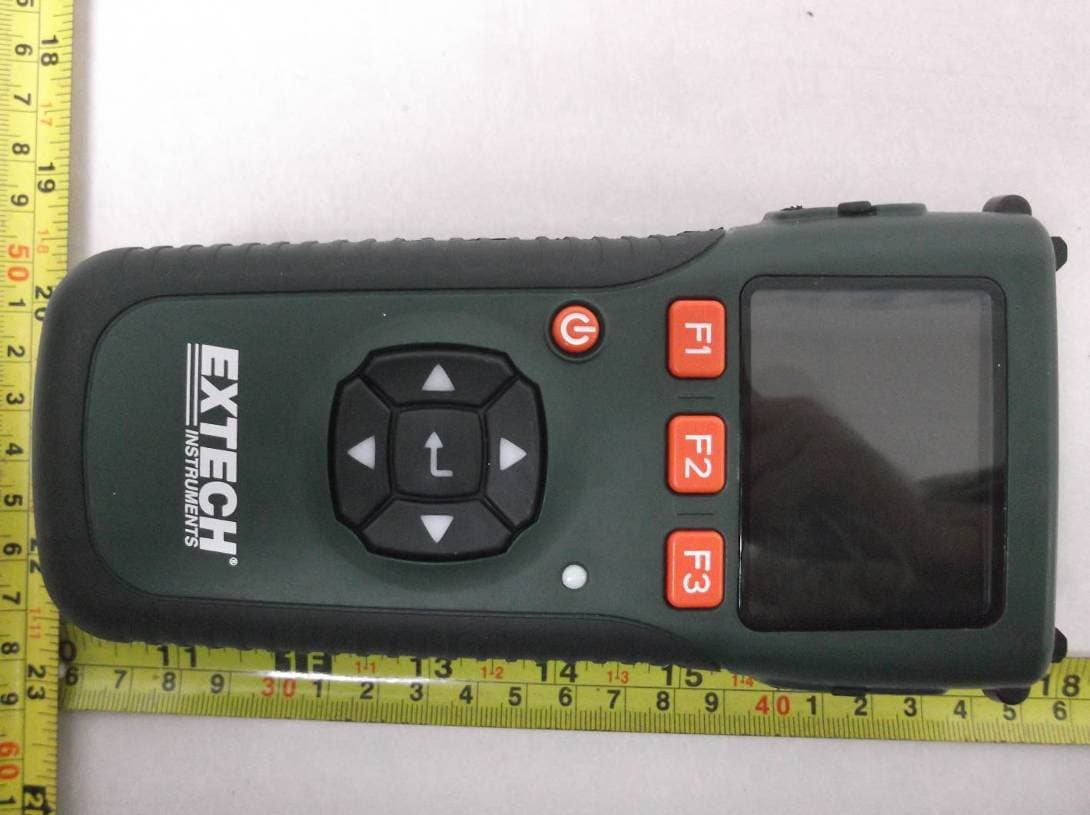
IWK-EX3000
Feb 13, 2012Wireless Receiver
Equipment Class
DXX - Part 15 Low Power Communication Device Transmitter